horn ISUZU TROOPER 1995 Owner's Manual
[x] Cancel search | Manufacturer: ISUZU, Model Year: 1995, Model line: TROOPER, Model: ISUZU TROOPER 1995Pages: 1928
Page 1469 of 1928
CHASSIS ELECTRICAL 8 ~ 277
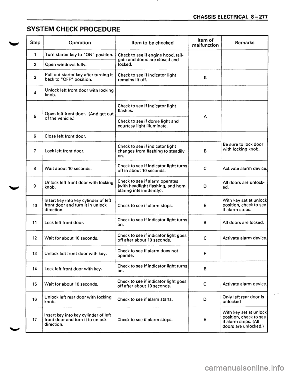
SYSTEM CHECK PROCEDURE
Step Operation Item to be checked Item of Remarks malfunction
1
Turn starter key to "ON" position. Check to see if engine hood, tail-
gate and doors are closed and
2
Open windows fully. locked.
3
Pull out starter key after turning it Check to see if indicator light K back to "OFF" position.
remains lit off.
4 Unlock
left
front door with locking
knob.
Check to see if indicator light
Open left front door. (And get out flashes.
5 A
of the vehicle.) Check to see if dome light and
courtesy light illuminate.
6 Close left front door.
Check to see if indicator light Be sure to lock door
7
Lock left front door.
changes from flashing to steadily B with locking knob.
on.
8 Wait about 10 seconds. Check to see if indicator light turns c Activate alarm device. off in about 10 seconds.
Unlock left
front door with locking Check to see if alarm operates All doors are unlock-9 knob. (with
headlight flashing, and horn D ed.
blaring intermittently).
Insert key into key cylinder of left With
key set at unlock
10 front door and turn it in unlock Check to see if alarm stops. E position, check to see
direction. if alarm stops.
11 Lock left front door. Check to see if indicator light turns
B All doors are locked.
on.
12 Wait for about 10 seconds. Check to see if indicator light goes c Activate alarm device. off after about 10 seconds.
13 Unlock left front door with key. Check to see if alarm does not F
operate.
14 Lock left front door with key. Check to see if indicator light turns
B
on.
15 Wait for about 10 seconds. Check to see if indicator light goes c Activate alarm device. off after about 10 seconds.
16 Unlock left rear door with locking Check to see if alarm starts. D Only left rear door is
knob. unlocked
Insert key
into key cylinder of left With
key set at unlock
position, check to see 17 front door and turn it to unlock Check to see if alarm stops. E if alarm stops. (All direction.
doors are unlocked.)
Page 1471 of 1928
CHASSIS ELECTRICAL 8-281
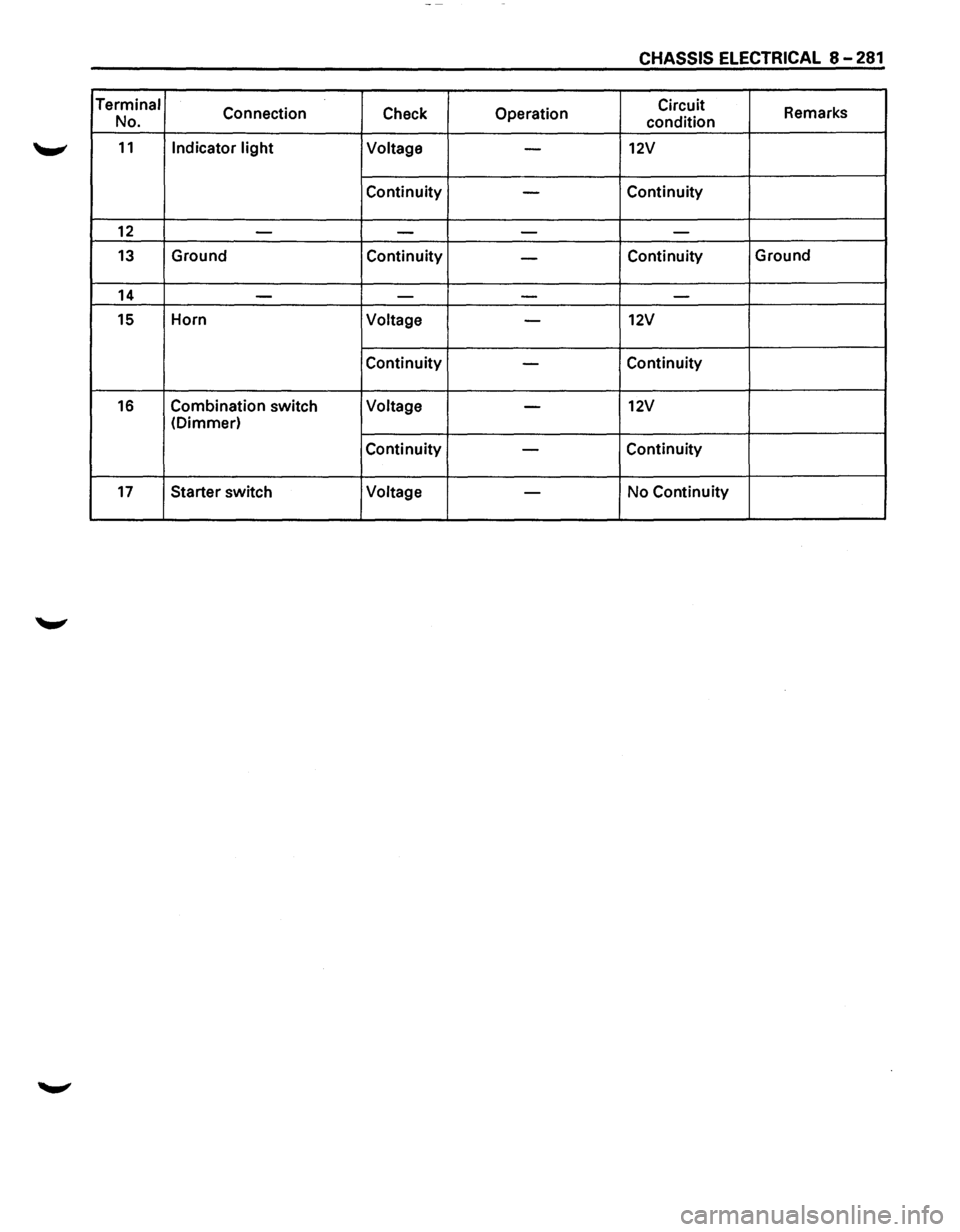
Terminal
Connection Check Operation Circuit
Remarks
No. condition
11 Indicator light Voltage -12V
Continuity -Continuity
12 ----
13 Ground
Continuity -Continuity Ground
14 ---
-
15 Horn
Voltage -12V
Continuity -Continuity
16 Combination switch Voltage -12V
(Dimmer)
Continuity
-Continuity
17 Starter switch Voltage -No
Continuity
Page 1473 of 1928
DOOR LOCK ACTUATOR (fRT DOOR
LH & RH, RR DOOR -LH & RH, TAIL-
~ GATE)
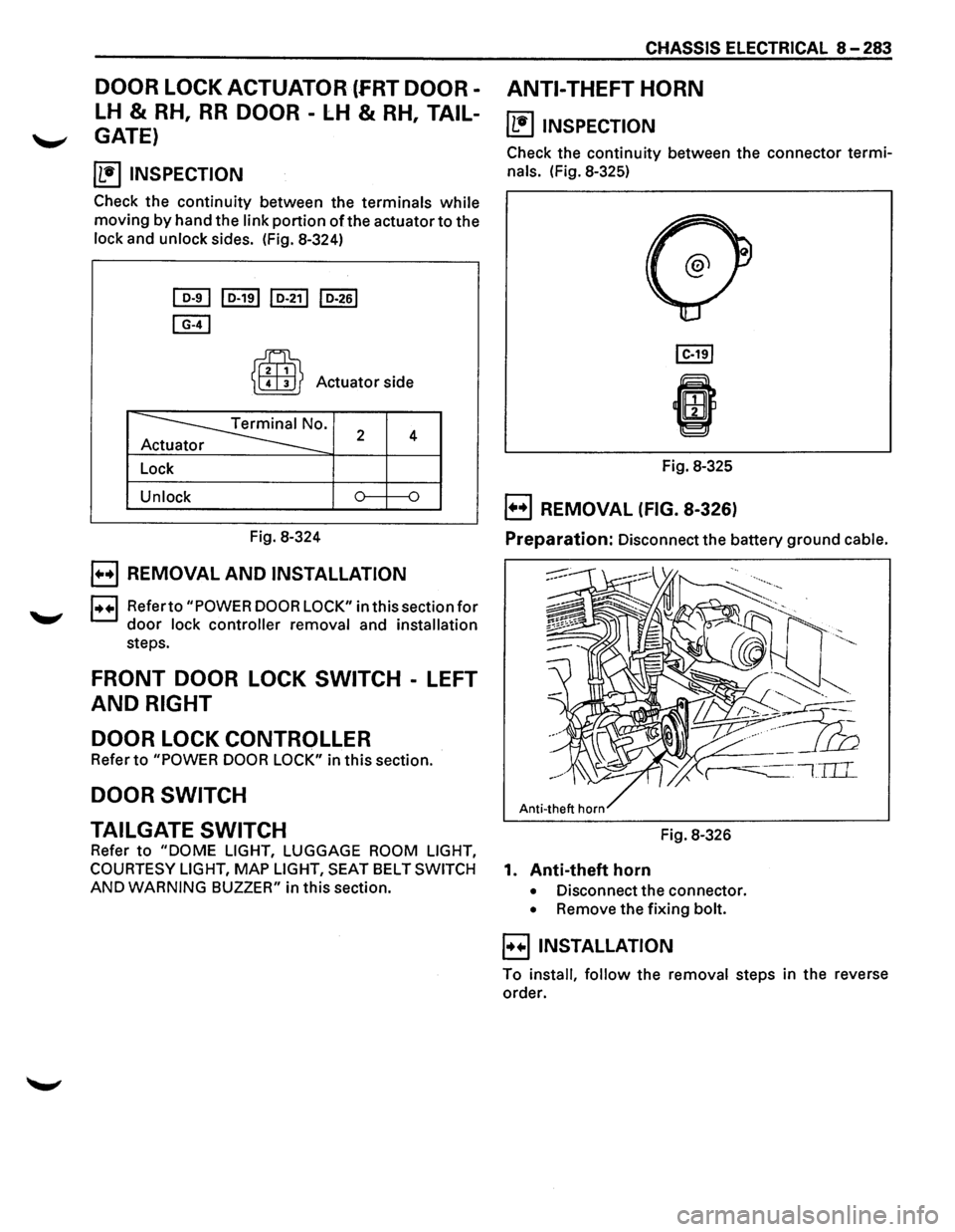
~ INSPECTION
Check the continuity between the terminals while
moving by hand the link portion of the actuator to the
lock and unlock sides. (Fig. 8-324)
[QI] I D-191 I D-211 I D-261
[E)
~
~ Actuator side
~· 2 4 r
Lock
Unlock
Fig. 8-324
B REMOVAL AND INSTALLATION
1++1 Referto "POWER DOOR LOCK" in this section for
door lock controller removal and installation
steps.
FRONT DOOR LOCK SWITCH -LEFT
AND RIGHT
DOOR LOCK CONTROLLER
Refer to "POWER DOOR LOCK" in this section.
DOOR SWITCH
CHASSIS ELECTRICAL 8-283
ANTI-THEFT HORN
~ INSPECTION
Check the continuity between the connector termi
nals. (Fig. 8-325)
Fig. 8-325
B REMOVAL (FIG. 8-326)
Preparation: Disconnect the battery ground cable.
TAILGATE SWITCH Fig. 8-326
Refer
to "DOME LIGHT, LUGGAGE ROOM LIGHT,
COURTESY LIGHT,
MAP LIGHT, SEAT BELT SWITCH 1. Anti-theft horn
AND WARNING BUZZER" in this section. • Disconnect the connector.
• Remove the fixing bolt.
B INSTALLATION
To install, follow the removal steps in the reverse
order.
Page 1505 of 1928
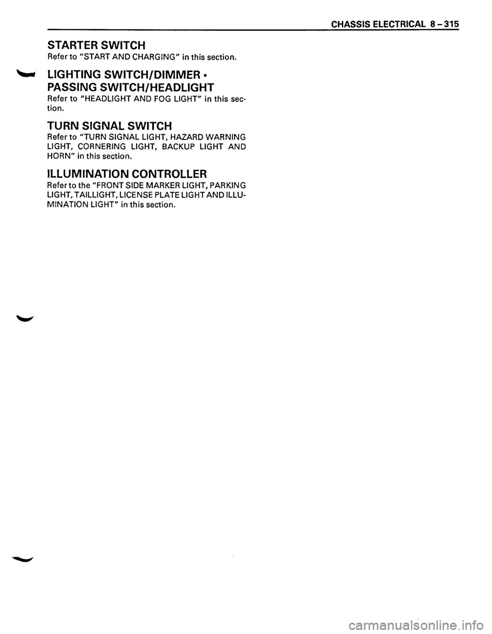
STARTER SWITCH
Refer to "START AND CHARGING" in this section.
'--LIGHTING SWITCH/DIMMER •
PASSING SWITCH/HEADLIGHT
Refer to "HEADLIGHT AND FOG LIGHT" in this sec-
tion.
TURN SIGNAL SWITCH
Refer to "TURN SIGNAL LIGHT, HAZARD WARNING
LIGHT, CORNERING LIGHT, BACKUP LIGHT AND
HORN" in this section.
ILLUMINATION CONTROLLER
Refer to the "FRONT SIDE MARKER LIGHT, PARKING
LIGHT, TAILLIGHT, LICENSE PLATE LIGHT AND ILLU
MINATION LIGHT"
in this section.
CHASSIS ELECTRICAL 8-315
Page 1749 of 1928
Supplemental Restraint System 9J-125
STEERING WHEEL
WARNING: SAFETY PRECAUTIONS MUST BE FOLLOWED WHEN HANDLING A DEPLOYED INFLATOR
MODULE(AIR BAG). AFTER DEPLOYMENT, THE INFLATOR MODULE(AIR BAG) SURFACE MAY CONTAIN A
SMALL AMOUNT OF SODIUM HYDROXIDE, A BY-PRODUCT OF THE DEPLOYMENT REACTION, THAT IS
IRRITATING TO
THE SKIN AND EYES. MOST OF THE POWDER ON THE INFLATOR MODULE (AIR BAG )IS
HARMLESS.
AS A PRECAUTION, WEAR GLOVES AND SAFETY GLASSES WHEN HANDLING A DEPLOYED
INFLATOR MODULE (AIR BAG ), AND WASH YOUR HANDS WITH MILD SOAP AND WATER AFTERWARDS.
WARNING: WHEN CARRYING A LIVE INFLATOR MODULE (AIR BAG ), MAKE SURE THE BAG AND TRIM
COVER
ARE POINTED AWAY FROM YOU. NEVER CARRY INFLATOR MODULE (AIR BAG )BY THE WIRES OR
CONNECTOR ON
THE UNDERSIDE OF MODULE. IN THE CASE OF AN ACCIDENTAL DEPLOYMENT, THE BAG
WILL THEN DEPLOY WITH MINIMAL CHANCE OF INJURY. WHEN PLACING A LIVE INFLATOR MODULE (AIR
BAG ) ON A BENCH OR OTHER SURFACE, ALWAYS FACE BAG AND TRIM COVER UP, AWAY FROM THE
SURFACE.NEVER
REST A STEERING COLUMN ASSEMBLY ON THE STEERING WHEEL WITH THE INFLATOR
MODULE (AIR BAG ) FACE DOWN AND COLUMN VERTICAL. THIS IS NECESSARY SO THAT A FREE SPACE
IS PROVIDED
TO ALLOW THE INFLATOR MODULE (AIR BAG) TO EXPAND IN THE UNLIKELY EVENT OF
ACCIDENTAL DEPLOYMENT. OTHERWISE, PERSONAL INJURY COULD RESULT.
NOTE: In
the event deployment has occurred, inspect coil assembly wire for any signs of scorching, melting or any
other damage due to excessive heat.
If the coil has been damaged, replace it.
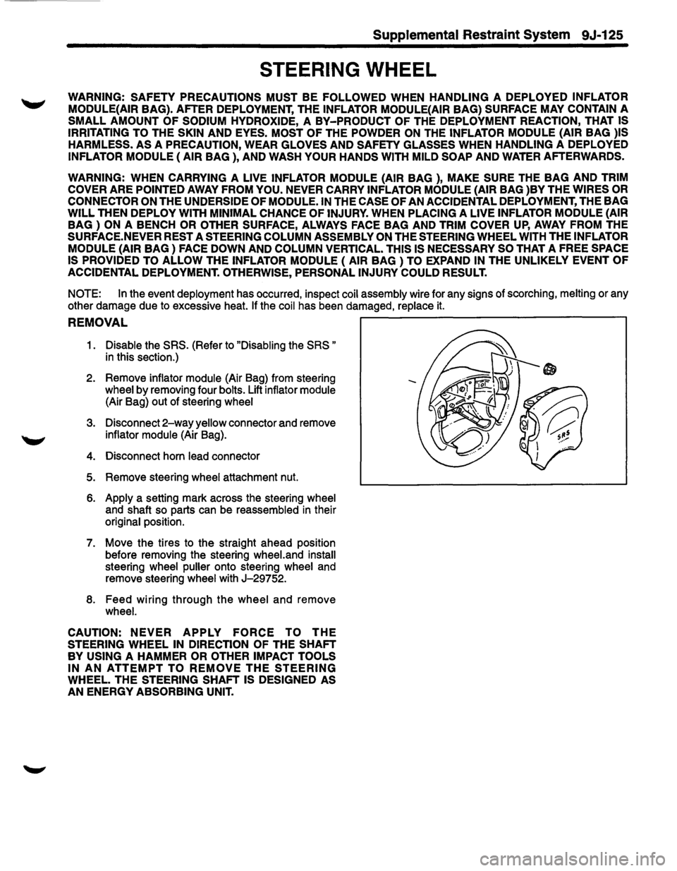
REMOVAL ~-----------------------------,
1. Disable the SRS. (Refer to "Disabling the SRS "
in this section.)
2. Remove
inflator module (Air Bag) from steering
wheel by removing four bolts. Lift inflator module
(Air Bag) out of steering wheel
3. Disconnect 2-way yellow connector and remove
inflator module (Air Bag).
4. Disconnect horn lead connector
5. Remove steering wheel attachment nut.
6. Apply a setting mark across the steering wheel
and shaft so parts can be reassembled in their
original position.
7.
Move the tires to the straight ahead position
before removing the steering
wheel.and install
steering wheel puller onto steering wheel and
remove steering
wheel with J-29752.
8. Feed wiring through the wheel and remove
wheel.
CAUTION:
NEVER APPLY FORCE TO THE
STEERING WHEEL IN DIRECTION OF THE SHAFT
BY USING A HAMMER OR OTHER IMPACT TOOLS
IN AN ATTEMPT TO REMOVE THE STEERING
WHEEL. THE STEERING SHAFT IS DESIGNED AS
AN ENERGY ABSORBING UNIT.
-
Page 1750 of 1928
9J-126 Supplemental Restraint System
INSTALLATION
1. Install the steering wheel and align the setting ~
marks.
2. Tighten the steering fixing nut to the specified
torque.
Torque : 34N·m(25 lb·ft.).
3. Connect horn lead connector.
4. Connect inflator module to 2-way yellow wiring
harness connector.
5. Install inflator module into steering wheel and
torque fasteners.
Torque: 8N·m(69 lb·in.)
6. Enable the SRS (Refer to "Enabling the SRS" in
this section.).
•
Page 1751 of 1928
Supplemental Restraint System 9J-127
SRS COIL ASSEMBLY
WARNING: SAFETY PRECAUTIONS MUST BE FOLLOWED WHEN HANDLING A DEPLOYED INFLATOR
MODULE{AIR
BAG). AFTER DEPLOYMENT, THE INFLATOR MODULE{AIR BAG) SURFACE MAY CONTAIN A
SMALL AMOUNT OF SODIUM HYDROXIDE, A BY-PRODUCT OF THE DEPLOYMENT REACTION, THAT IS
IRRITATING TO
THE SKIN AND EYES. MOST OF THE POWDER ON THE INFLATOR MODULE (AIR BAG )IS
HARMLESS.
AS A PRECAUTION, WEAR GLOVES AND SAFETY GLASSES WHEN HANDLING A DEPLOYED
INFLATOR MODULE {AIR BAG ), AND WASH YOUR HANDS WITH MILD SOAP AND WATER AFTERWARDS.
WARNING: WHEN CARRYING A LIVE INFLATOR MODULE {AIR BAG ), MAKE SURE THE BAG AND TRIM
COVER
ARE POINTED AWAY FROM YOU. NEVER CARRY INFLATOR MODULE {AIR BAG )BY THE WIRES OR
CONNECTOR ON
THE UNDERSIDE OF MODULE. IN THE CASE OF AN ACCIDENTAL DEPLOYMENT, THE BAG
WILL THEN DEPLOY WITH MINIMAL CHANCE OF INJURY. WHEN PLACING A LIVE INFLATOR MODULE (AIR
BAG ) ON A BENCH OR OTHER SURFACE, ALWAYS FACE BAG AND TRIM COVER UP, AWAY FROM THE
SURFACE. NEVER REST A STEERING COLUMN ASSEMBLY ON THE STEERING WHEEL WITH THE INFLATOR
MODULE (AIR BAG) FACE DOWN AND COLUMN VERTICAL. THIS IS NECESSARY SO THAT A FREE SPACE
IS PROVIDED TO
ALLOW THE INFLATOR MODULE { AIR BAG ) TO EXPAND IN THE UNLIKELY EVENT OF
ACCIDENTAL
DEPLOYMENT. OTHERWISE, PERSONAL INJURY COULD RESULT.
NOTE:
In the event deployment has occurred, inspect coil assembly wire for any signs of scorching, melting or any
other damage due to excessive heat.
If the coil has been damaged, replace it.
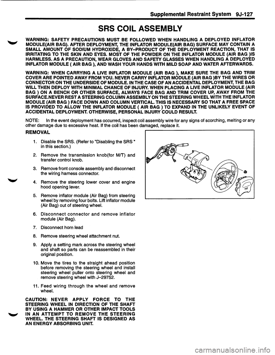
REMOVAL ~------------------------------------------,
1. Disable the SRS. (Refer to "Disabling the SRS"
in this section.)
2. Remove the transmission knob(for
MIT) and
transfer
control knob.
3. Remove front console assembly and disconnect
the wiring harness connector.
4. Remove the steering lower cover and engine
hood opening
lever.
5. Remove inflator module (Air Bag) from steering
wheel by removing four bolts. Lift inflator module
(Air Bag) out of steering wheel.
6. Disconnect connector and remove inflator
module (Air Bag).
7. Disconnect horn lead
8. Remove steering wheel attachment nut.
9. Apply a setting mark across the steering wheel
and shaft so parts can be reassembled in their
original position.
10. Move the tires to the straight ahead position
before removing the steering
wheel and install
steering wheel puller onto steering wheel and
remove steering
wheel with J-29752.
11. Feed wiring through the wheel and remove
wheel.
CAUTION:
NEVER APPLY FORCE TO THE
STEERING WHEEL IN DIRECTION OF THE SHAFT
BY USING A HAMMER OR OTHER IMPACT TOOLS
~ IN AN ATTEMPT TO REMOVE THE STEERING
WHEEL. THE STEERING SHAFT IS DESIGNED AS
AN ENERGY ABSORBING UNIT.
Page 1752 of 1928
9J-128 Supplemental Restraint System
12. Remove steering column cover.
13. Disconnect the wiring harness connectors ~
located base of steering column.
14. Remove the combination switch assembly with
SRScoil.
NOTE: SRS
coil is a part of combination switch
assembly, which
cannot be replaced individually.
Therefore, be sure not to remove the
SRS coil from the
combination switch assembly.
INSTALLATION
1. Install the combination switch assembly with
SRScoil.
2. Connect the wiring harness connector located In
base of steering column.
3. Turn the SRS coil clockwise to full, return about
3 turns and align the neutral mark.
CAUTION: WHEN TURNING THE SRS COIL
CLOCKWISE TO FULL, STOP TURNING IF
RESISTANCE IS FELT. FORCED FURTHER
TURNING MAY CAUSE DAMAGE TO THE CABLE IN
THE SRS COIL.
4. Install steering column cover.
CAUTION: WHEN INSTALLING THE STEERING
COLUMN COVER, BE SURE TO WIRE (THROUGH ~
EACH HARNESS) AS ILLUSTRATED SO THAT THE
HARNESSES OF STARTER SWITCH,COMBINATION
SWITCH
AND SRS COIL MAY NOT CATCH WIRING.
5. Install the steering wheel and align the setting
marks.
6. Tighten the steering fixing nut to the specified
torque.
Torque : 34N·m(25 lb·ft.).
7. Connect horn lead connector.
8. Connect inflator module to 2-way yellow wiring
harness connector.
9. Install inflator module into steering wheel and
torque fasteners.
NOTE: Always replace inflator module {Air Bag)
fasteners with new fasteners. Never reuse old fasteners.
Torque: 8N·m(69 lb·ln.)
10. Install the steering lower cover and engine hood
opening lever.
11. Install front console assembly and connect the
wiring harness connector.
12. Install the transmission knob{for M/T) and
transfer control knob. ~
13. Enable the SRS (Refer to "Enabling the SRS" in
this section.).
•
Page 1753 of 1928
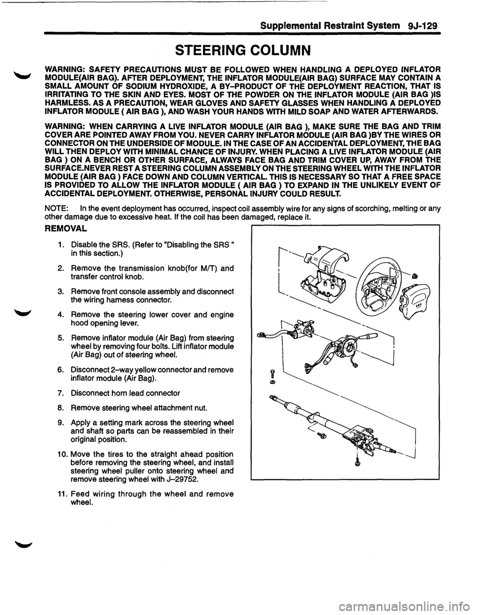
Supplemental Restraint System 9J-129
STEERING COLUMN
WARNING: SAFETY PRECAUTIONS MUST BE FOLLOWED WHEN HANDLING A DEPLOYED INFLATOR
MODULE{AIR
BAG). AFTER DEPLOYMENT, THE INFLATOR MODULE{AIR BAG) SURFACE MAY CONTAIN A
SMALL AMOUNT OF SODIUM HYDROXIDE, A BY-PRODUCT OF THE DEPLOYMENT REACTION, THAT IS
IRRITATING TO
THE SKIN AND EYES. MOST OF THE POWDER ON THE INFLATOR MODULE (AIR BAG )IS
HARMLESS.
AS A PRECAUTION, WEAR GLOVES AND SAFETY GLASSES WHEN HANDLING A DEPLOYED
INFLATOR MODULE (AIR BAG ), AND WASH YOUR HANDS WITH MILD SOAP AND WATER AFTERWARDS.
WARNING: WHEN CARRYING A LIVE INFLATOR MODULE {AIR BAG ), MAKE SURE THE BAG AND TRIM
COVER
ARE POINTED AWAY FROM YOU. NEVER CARRY INFLATOR MODULE (AIR BAG )BY THE WIRES OR
CONNECTOR ON
THE UNDERSIDE OF MODULE. IN THE CASE OF AN ACCIDENTAL DEPLOYMENT, THE BAG
WILL THEN DEPLOY WITH MINIMAL CHANCE OF INJURY. WHEN PLACING A LIVE INFLATOR MODULE (AIR
BAG ) ON A BENCH OR OTHER SURFACE, ALWAYS FACE BAG AND TRIM COVER UP, AWAY FROM THE
SURFACE.NEVER REST A STEERING COLUMN ASSEMBLY ON THE STEERING WHEEL WITH THE INFLATOR
MODULE {AIR
BAG) FACE DOWN AND COLUMN VERTICAL. THIS IS NECESSARY SO THAT A FREE SPACE
IS PROVIDED TO
ALLOW THE INFLATOR MODULE (AIR BAG) TO EXPAND IN THE UNLIKELY EVENT OF
ACCIDENTAL
DEPLOYMENT. OTHERWISE, PERSONAL INJURY COULD RESULT.
NOTE:
In the event deployment has occurred, inspect coil assembly wire for any signs of scorching, melting or any
other damage due to excessive heat.
If the coil has been damaged, replace it.
REMOVAL ~--------------------------~
1. Disable the SRS. (Refer to "Disabling the SRS "
in this section.)
2. Remove the transmission knob(for MIT) and
transfer
control knob.
3. Remove front console assembly and disconnect
the wiring harness connector.
4. Remove the steering lower cover and engine
hood opening
lever.
5. Remove inflator module (Air Bag) from steering
wheel by removing four bolts. Lift inflator module
(Air Bag) out of steering wheel.
6. Disconnect 2-way yellow connector and remove
inflator module (Air Bag).
7. Disconnect horn lead connector
8. Remove steering wheel attachment nut.
9. Apply a setting mark across the steering wheel
and shaft so parts can be reassembled in their
original position.
1
0. Move the tires to the straight ahead position
before removing the steering
wheel, and install
steering wheel puller onto steering wheel and
remove steering
wheel with J-29752.
11. Feed wiring through the wheel and remove
wheel.
y
®
Page 1755 of 1928
1 o. Connect the wiring harness connector located
base of steering column.
11. Turn the SRS coil clockwise to full, return about
3 turns and align the neutral mark.
CAUTION: WHEN TURNING THE SRS COIL
CLOCKWISE TO FULL, STOP TURNING IF
RESISTANCE IS FELT. FORCED FURTHER
TURNING MAY CAUSE DAMAGE TO THE CABLE IN
THE SRS COIL.
12. Install steering column cover.
CAUTION: WHEN INSTALLING THE STEERING
COLUMN COVER,
BE SURE TO WIRE {THROUGH
EACH HARNESS) AS ILLUSTRATED SO THAT THE
HARNESSES OF STARTER SWITCH,COMBINATION
SWITCH
AND SRS COIL MAY NOT CATCH WIRING.
13. Install the steering wheel and align the setting
marks.
14. Tighten the steering fixing nut to the specified
torque.
Torque: 34N·m(25 lb·ft.).
15. Connect horn lead connecor.
16. Connect inflator module to
2-way yellow wiring
harness connector.
17.
Install inflator module into steering wheel and
torque fasteners.
Torque: 8N·m(69 lb-in.)
18. Install the steering lower cover and engine hood
opening lever.
19.
Install front console assembly and connect the
wiring harness connector.
20.
Install the transmission knob(for M/T) and
transfer control knob.
21. Enable the
SRS (Refer to "Enabling the SRS" in
this section.).
Supplemental Restraint System 9J-131