maintenance ISUZU TROOPER 1995 User Guide
[x] Cancel search | Manufacturer: ISUZU, Model Year: 1995, Model line: TROOPER, Model: ISUZU TROOPER 1995Pages: 1928
Page 26 of 1928
OB-10 MAINTENANCE AND LUBRICATION
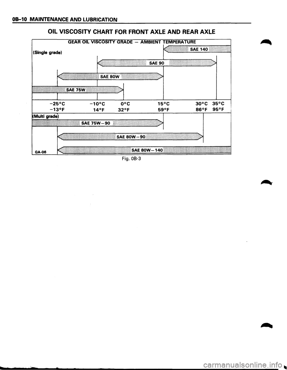
OIL VISCOSITY CHART FOR FRONT AXLE AND REAR AXLE
(Single grade)
15°C 30°C 35°C
59°F 86°F 95°F
GA-06
Fig. OB-3
Page 27 of 1928
,
MAINTENANCE AND LUBRICATION OB-11
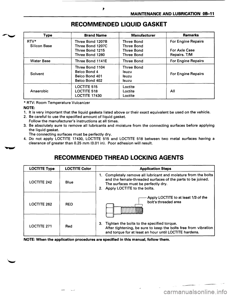
RECOMMENDED LIQUID GASKET
Type Brand Name Manufacturer Remarks
RTV* Three Bond
1207B Three Bond For
Engine Repairs
Silicon Base
Three Bond 1207C Three Bond
Three Bond 1215 Three Bond For
Axle Case
Three Bond
1280 Three Bond Repairs.
T/M
Water Base
Three Bond 1141E Three Bond For
Engine Repairs
Three Bond
1104 Three Bond
Solvent Belco Bond
4 lsuzu For Engine Repairs Belco Bond 401 lsuzu
Belco
Bond 402 lsuzu
LOCTITE
515 Loctite
Anaerobic
LOCTITE 518 Loctite All
LOCTITE
17 430 Loctite
*
RTV: Room Temperature Vulcanizer
NOTE:
1. It is very important that the liquid gaskets listed above or their exact equivalent be used on the vehicle.
2. Be careful to use the specified amount of liquid gasket.
Follow the manufacturer's instructions at all times.
3. Be absolutely sure to remove all lubricants and moisture from the connecting surfaces before applying
the liquid gasket.
The connecting surfaces
must be perfectly dry.
4. Do not apply LOCTITE 17430, LOCTITE 515 and LOCTITE 518 between two metal surfaces having a
clearance
of greater than 0.25 mm (0.01 in). Poor adhesion will result.
RECOMMENDED THREAD LOCKING AGENTS
LOCTITE Type LOCTITE Color Application Steps
1. Completely remove all lubricant and moisture from the bolts
LOCTITE 242 Blue and the female-threaded surfaces of the parts to be joined.
The surfaces
must be perfectly dry.
2. Apply LOCTITE to the bolts.
~Apply LOCTITE to at least 1/3 of the
LOCTITE 262 RED ,.-bolt's threaded area
~
1\\\\\\\W
'--
LOCTITE 271 Red 3. Tighten the bolts to the specified torque.
After tightening, be sure
to keep the bolts free from vibration
and torque
for at least an hour until LOCTITE hardens.
NOTE: When the application procedures are specified in this manual, follow them.
Page 28 of 1928
OB-12 MAINTENANCE AND LUBRICATION
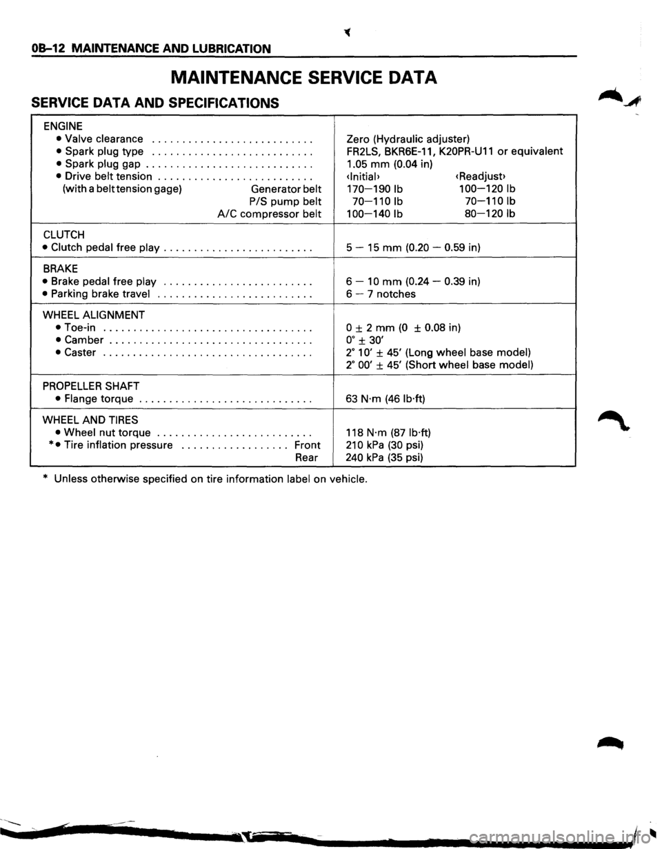
MAINTENANCE SERVICE DATA
SERVICE DATA AND SPECIFICATIONS
ENGINE
• Valve clearance I o o I I I 0 0 0 I 0 o o o o o I 0 o o o 0 0 o o o o Zero (Hydraulic adjuster)
• Spark plug type I I o 0 I o 0 I I I 0 o o o I 0 I o o 0 0 0 o o 0 0 0 FR2LS, BKR6E-1 1, K20PR-U11 or equivalent
•
Spark plug gap ............................ 1.05 mm (0.04 in)
• Drive belt tension ..........................
(with a belttension gage)
Generator belt 170-190 lb 100-120 lb
PIS
pump belt 70-110 lb 70-110 lb
A/C compressor belt 100-140 lb 80-120 lb
CLUTCH
• Clutch pedal free play ......................... 5 -15 mm (0.20 -0.59 in)
BRAKE
• Brake pedal free play o o o o o o o o 0 0 o o o o o 0 0 o o 0 I o o o o 6 -10 mm (0.24 -0.39 in)
• Parking brake travel ••••••••••••••••••\
•• 0 ••••• 6-7 notches
WHEEL
ALIGNMENT
•
Toe-in 0 0 o o 0 0 I 0 0 o o o o 0 0 0 0 o o o o I 0 0 o o 0 0 o o o o 0 I 0 0 ± 2 mm (0 ± 0.08 in)
• Camber .................................. oo ± 30'
•
Caster o o o 0 0 0 0 o o o o o o I 0 0 o o o o 0 0 o o o o 0 o o o o o 0 0 o 2° 1 0' ± 45' (Long wheel base model)
2° 00' ± 45' (Short wheel base model)
PROPELLER SHAFT
• Flange torque ••••••••••••••••••\
•• 0' ••• 0 ••• 63 N·m (46 lb·ft)
WHEEL AND TIRES
• Wheel nut torque o o o o 0 0 o o o o o o o o o o o I o o o o 0 0 0 o 118 N·m (87 lb·ft)
* • Tire inflation pressure •••••••••••••• 0 ••• Front 21 0 kPa (30 psi)
Rear
240 kPa (35 psi)
* Unless otherwise specified on tire information label on vehicle.
~~-.... ¢ .............. .-I ~ -.,~iii~-..--. ....... 2 ........ -. .................. ~~ - I
Page 29 of 1928
MAINTENANCE AND LUBRICATION OB-13
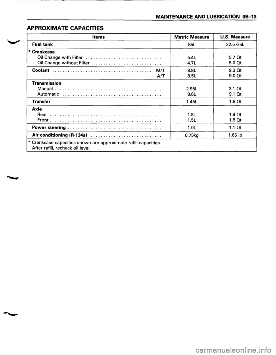
APPROXIMATE CAPACITIES
Items Metric Measure U.S. Measure
Fuel tank 85L 22.5 Gal.
*Crankcase
Oil Change with Filter .............................. 5.4L 5.7 at
Oil Change without Filter ••••••••••••••••••\
0 •••• 0 ••• 4.7L
5.0 at
Coolant ........................................ MIT 8.8L 9.3 at
A/T 8.5L 9.0 at
Transmission
Manual
.......................................... 2.95L 3.1 at
Automatic ••••••••••••••••••\
•• 0 •••• 0 0 0 ••••••••••• 8.6L 9.1 at
Transfer
1.45L 1.5 at
Axle
Rear o o o 0
0 0 0 0 0 0 0 0 0 0 0 0 0 0 0 0 I 0 0 0 o o o o o o o 0 0 0 0 0 0 0 0 0 0 0 o o 1.8L 1.9 at
Front ........................................ ~ ... 1.5L 1.6 at
Power steering ••• 0 ••••••••• 0 ••••••••••••••••••\
0 •••• 1.0L 1.1 at
Air conditioning (R-134a) o o 0
0 0 0 0 0 0 0 0 I 0 0 0 0 0 o o 0 o 0 0 0 0 0 0 0 0.75kg 1.651b
* Crankcase capacities shown are approximate refill capacities.
After
refill, recheck oil level.
Page 139 of 1928
POWER STEERING GEAR AND PUMP 381 -1
SECTION 381
POWER STEERING GEAR AND PUMP
w CAUTION:
When fasteners are removed, always reinstall them at the same location from which they were removed.
If a fastener needs to be replaced, use the correct part number fastener for that application. If the correct
part
number fastener is not available, a fastener of equal size and strength (or stronger) may be used.
Fasteners
that are not reused, and those requiring thread locking compound, will be called out. The correct
torque value must be used when installing fasteners that require it. If the above conditions are not
followed, parts or system damage could result.
CONTENTS
General Description ............................ 3B1- 1
Steering Wheel Free Play Adjustment .... 3B1-5
Power Steering
Gear........................ 3B1-1
Steering Gear ................................ 3B1-6
Hydraulic Pump .............................. 3B1- 1
Power Steering Pump ...................... 3B1-8
Pressure Switch
............................. 3B1-1
Unit Repair ...................................... 3B1- 9
Power Steering System Test
................. 3B1-3
Steering Gear ................................ 3B1-9
On-Vehicle Service ............................. 3B1- 4
Power Steering Pump ...................... 3B1-14
Maintenance
................................. 3B1- 4
Main Data and Specifications ................ 3B1-17
Fluid Level .................................... 3B1- 4 General Specifications ...................... 3B1-17
Bleeding The Power Steering System .... 3B1-4
Torque Specifications ....................... 3B1-17
Bleeding Procedure ......................... 3B1-4 Special Tools.................................... 3B1-18
Flushing The Power Steering System .... 3B1-4
GENERAL DESCRIPTION
The hydraulic power steering system consists of a
pump, an oil reservoir, a steering gear, a pressure
hose and a return hose.
POWER STEERING GEAR
The power steering gear has a recirculating ball
system which acts as a rolling thread between the
worm shaft and the rack piston. When the worm shaft
is
turned right, the rack piston moves up in gear.
Turning the worm shaft left moves the rack piston
down in gear. The rack piston teeth mesh with the
sector, which is part ofthe sector shaft.
Turning the worm shaft turns the sector shaft, which
turns the wheels through the steering linkage.
The control valve in the steering gear directs the
power steering fluid to either side of the rack piston.
The rack
piston converts the hydraulic pressure into
a mechanical force. If the steering system becomes
damaged and loses hydraulic pressure, the vehicle
can be controlled manually (Fig. 381-1).
HYDRAULIC PUMP
The hydraulic pump is vane-type design. The
submerged pump has housing and internal parts that
are inside the reservoir and operate submerged in oil.
There are two bore openings at the rear of the pump
housing. The larger opening contains the cam ring,
pressure
plate, thrust plate, rotor and vane assembly,
and end plate. The smaller opening contains the
pressure
line union, flow control valve and spring
(Fig. 381-2).
PRESSURE SWITCH
When hydraulic pressure reaches 3920 ± 690 kPa
(570 ± 100 psi), the pressure switch closes causing
Engine
Control Module (ECM) to actuate the idle air
control valve to prevent the overload-induced engine
speed down. The switch opens
when hydraulic
pressure drops to 2970 ± 560 kPa (430 ± 80 psi).
Page 142 of 1928
381 - 4 POWER STEERING GEAR AND PUMP
ON-VEHICLE SERVICE
MAINTENANCE
The hydraulic system should be kept clean and fluid
level in the reservoir should be checked at regular
intervals
and fluid added when required. Refer to
"MAINTENANCE AND LUBRICATION" in section OB
ofthe manual for type offluid to be used and intervals
for filling.
If the system contains some dirt, flush it as detailed
later
in this section. If it is exceptionally dirty, both the
pump and the gear must be completely disassembled
before further usage.
All tubes, hoses, and fittings should be inspected for
leakage at regular intervals. Fittings must be tight.
Make sure the clips, clamps and supporting tubes and
hoses are in
place and properly secured.
Power steering hoses and lines must not be twisted,
kinked or tightly bent. Air in the system will cause
spongy action and noisy operation. When a hose is
disconnected
or when fluid is lost, for any reason, the
system must be bled after refilling. Refer to "Bleeding
the Power Steering System" in this section.
FLUID LEVEL
1. Run the engine until the power steering fluid
reaches normal operating temperature, about
55°C (130°F), then shut the engine off.
2. Check the level of fluid in the reservoir.
3. If the fluid level is low, add power steering fluid
as specified in "MAINTENANCE AND LUBRI
CATION" in Section OB to the proper level and
install the receiver cap.
4. When checking the fluid level after the steering
system has been serviced,
air must be bled from
the system. Refer to "Bleeding the Power
Steering
System" in this section.
BLEEDING THE POWER STEERING
SYSTEM
When a power steering pump or gear has been
installed, or an oil line has been disconnected, the air
that has entered the system must be bled out before
the vehicle is operated. If air is allowed to remain in
the power steering fluid system, noisy and
unsatisfactory operation of the system may result.
BLEEDING PROCEDURE
When bleeding the system, and any time fluid is
added
to the power steering system, be sure to use
only power steering fluid as specified in
"MAINTENANCE AND LUBRICATION" in section OB.
1. Fill the pump fluid reservoir to the proper level
and let the fluid settle for at least two minutes.
2. Start the engine and let it run for a few seconds.
Do
not turn the steering wheel. Then turn the
engine off.
3. Add fluid if necessary.
4. Repeat the above procedure until the fluid level
remains constant after running the engine.
5. Raise the front end of the vehicle so that the
wheels are off the ground.
6. Start the engine. Slowly turn the steering wheel
right and left, lightly contacting the wheel stops.
7. Add power steering fluid if necessary.
8. Lower the vehicle and turn the steering wheel
slowly from lock to lock.
9. Stop the engine. Check the fluid level and refill
as required.
10.
If the fluid is extremely foamy, allow the vehicle
to stand a few minutes and repeat the above
procedure.
~ INSPECT
• Belt for tightness.
• Pulley for looseness or damage. The pulley
should not wobble with the engine running.
• Hoses so they are not touching any other parts
of the vehicle.
• Fluid level
and fill to the proper level.
FLUSHING THE POWER STEERING
SYSTEM
1. Raise the front end of the vehicle off the ground
until the wheels are free to turn.
2. Remove the fluid return line at the pump inlet
connector and plug the connector port on the
pump.
Position the line toward a large container to
catch the draining fluid.
3. While running the engine at idle, fill the reservoir
with new power steering fluid. Turn the steering
wheel in both directions. DO NOT contact wheel
stops or hold the wheel in a corner, or fluid will
stop and the pump will be in pressure relief mode.
A sudden
overflow from the reservoir may
develop if the wheel is held at a stop.
4. Install all the lines and hoses. Fill the system with
new power steering fluid and bleed the system
as described in "Bleeding The Power Steering
System". Operate the engine for about 15
minutes.
Remove the
pump return line at the pump inlet
and plug the connection on the pump. While
refilling the reservoir, check the draining fluid for
contamination. If foreign material is still evident,
replace all lines, disassemble and clean or replace
the power steering system components. Do not
re-use any drained power steering fluid.
~
~
Page 279 of 1928
FRONT DRIVING AXLE 4C-1
SECTION 4C
FRONT DRIVING AXLE
'f CAUTION:
When fasteners are removed, always reinstall them at the same location from which they were removed.
If a fastener needs to be replaced, use the correct part number fastener for that application. If the correct
part
number fastener is not available, a fastener of equal size and strength (or stronger) may be used.
Fasteners
that are not reused, and those requiring thread locking compound, will be called out. The
correct
torque values must be used when installing fasteners that require torque. If the above conditions
are not followed, parts or system damage could result.
CONTENTS
General Description . . . . . . . . . . . . . . . . . . . . 4C-1
Diagnosis
of Front Driving Axle . . . . . . . . . . . 4C-2
Automatic Locking Free Wheel Hub . . . . . 4C-3
On-Vehicle Service ..................... 4C- 4
Pinion
Shaft Oil Seal Replacement . . . . . . 4C-4
Front Drive Shaft Joints Replacement . . . 4C-5
Front Hub Bearing Preload Check . . . . . . . 4C-5
Unit Repair . . . . . . . . . . . . . . . . . . . . . . . . . . . . 4C-6
Front Drive Axle Assembly . . . . . . . . . . . . 4C-6
Front Axle Drive Shaft . . . . . . . . . . . . . . . . 4C-9
Differential Assembly ................. 4C-14
Differential Cage Assembly . . . . . . . . . . . . 4C-24
Front Hub and Disc (4WD Model with
Automatic Locking Hub) . . . . . . . . . . . . 4C-28
Main Data and Specifications . . . . . . . . . . . . 4C-37
General Specifications . .
. . . . . . . . . . . . . . 4C-37
Torque Specifications ................. 4C-38
Special Tools .......................... 4C-41
GENERAL DESCRIPTION
This publication contains essential removal, instal
lation,
adjustment and maintenance procedures.
The
front axle utilizes a central disconnect type front
axle/transfer case system. The
drive axles are completely flexible assemblies,
consisting
of inner and outer constant velocity (CV)
drive shaft joints connected by an axle shaft. For
description
of front propeller shaft and universal
joint, refer to Section 4A "PROPELLER SHAFT".
Page 331 of 1928
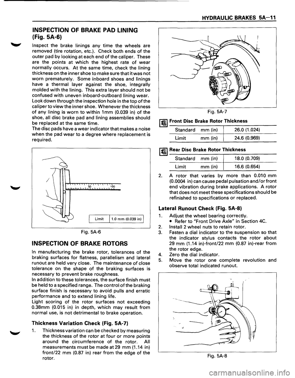
INSPECTION OF BRAKE PAD LINING
(Fig. SA-6)
Inspect the brake linings any time the wheels are
removed (tire rotation, etc.). Check both ends
of the
outer pad by
looking at each end of the caliper. These
are the points at which the highest rate
of wear
normally occurs. At the same time, check the lining
thickness on the inner shoe to make sure that it was not
worn prematurely. Some inboard shoes and linings
have a thermal layer against the shoe, integrally
molded
with the lining. This extra layer should not be
confused with uneven inboard-outboard lining wear.
Look
down through the inspection hole in the top of the
caliper to view the inner shoe. Whenever the thickness
of any lining is worn to within 1 mm (0.039 in) of the
shoe,
all disc brake pad and lining assemblies should
be replaced at the same time.
The disc pads have a
wear indicator that makes a noise
when the pad wear to a degree where replacement is
required.
100
Limit 11.0 mm (0.039 in) I
Fig. 5A-6
INSPECTION OF BRAKE ROTORS
In manufacturing the brake rotor, tolerances of the
braking surfaces
for flatness, parallelism and lateral
runout are held very close. The maintenance of close
tolerance
on the shape of the braking surfaces is
necessary to prevent brake roughness.
In addition to these tolerances, the surface finish must
be held to a specified range. The control ofthe braking
surface finish is necessary to avoid
pulls and erratic
performance and to extend
lining life.
Light scoring of the rotor surfaces not exceeding
0.38mm (0.015 in) in depth, which may result from
normal use, is not detrimental to brake operation.
Thickness Variation Check (Fig. 5A-7)
1. Thickness variation can be checked by measuring
the thickness
of the rotor at four or more points
around the circumference
of the rotor. All
measurements must be made at 29 mm (1.14 in)
front/22 mm (0.87 in) rear from the edge of the
rotor.
HYDRAULIC BRAKES 5A-11
Fig. 5A-7
~~~ Front Disc Brake Rotor Thickness
Standard mm (in) 26.0 (1.024)
Limit mm(in) 24.6 (0.969)
~~~Rear Disc Brake Rotor Thickness
Standard mm (in) 18.0 (0.709)
Limit mm (in) 16.6 (0.654)
2. A rotor that varies by more than 0.010 mm
(0.0004 in) can cause pedal pulsation and/or front
end vibration during brake applications. A rotor
that does not meet these specifications should be
refinished
to specifications or replaced.
Lateral Runout Check (Fig. 5A-8)
1. Adjust the wheel bearing correctly.
• Refer to "Front Drive Axle" in Section 4C.
2. Install 2 wheel nuts to retain rotor.
3. Fasten a dial indicator to the suspension so that
the indicator stylus contacts the rotor about
29 mm (1.14 in)-front/22 mm (0.87 in)-rear from
the rotor edge.
4. Zero the dial indicator.
5. Move the rotor one complete revolution and
observe
total indicated runout.
Fig. 5A-8
Page 354 of 1928
5A2-4 DISC BRAKES
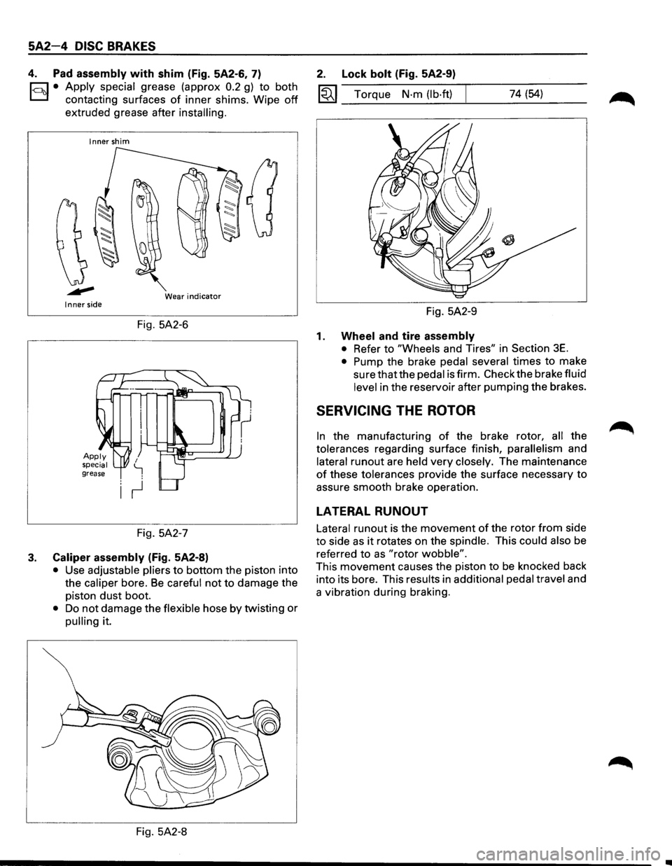
4. Pad assembly with shim (Fig. 5A2-6, 7)
1-c::~t:.l• Apply ~pecial grease (approx 0.2 g) to both
contactmg surfaces
of inner shims. Wipe off
extruded grease after installing.
Inner shim
Wear
indicator Inner side
Fig. 5A2-6
Fig. 5A2-7
3. Caliper assembly (Fig. 5A2-8)
• Use adjustable pliers to bottom the piston into
the
caliper bore. Be careful not to damage the
piston
dust boot.
• Do not damage the flexible hose by twisting or
pulling it.
Fig. 5A2-8
2. Lock bolt (Fig. 5A2-9)
1«1 Torque N·m (lb·ft) 74 (54)
Fig. 5A2-9
1. Wheel and tire assembly
• Refer to "Wheels and Tires" in Section 3E.
• Pump the brake pedal several times to make
sure that the pedal is firm. Check the brake fluid
level in the reservoir after pumping the brakes.
SERVICING THE ROTOR
In the manufacturing of the brake rotor, all the
tolerances regarding surface finish,
parallelism and
lateral
runout are held very closely. The maintenance
of these tolerances provide the surface necessary to
assure smooth brake operation.
LATERAL RUNOUT
Lateral runout is the movement of the rotor from side
to side as it rotates on the spindle. This could also be
referred
to as "rotor wobble".
This movement causes the piston to be knocked back
into its bore. This results in
additional pedal travel and
a vibration during braking.
Page 360 of 1928
5A2-12 DISC BRAKES
1. Wheel and tire assembly
• Refer to "Wheels and Tires" in Section 3E.
• Pump the brake pedal several times to
make sure that the pedal
is firm. Check the
brake fluid level in the reservoir after
pumping the brakes.
SERVICING THE ROTOR
In the manufacturing of the brake rotor, all the
tolerances regarding surface finish, parallelism and
lateral runout are held very closely. The maintenance
of these tolerances provide the surface necessary to
assure smooth brake operation.
LATERAL RUNOUT
Lateral runout is the movement of the rotor from side
to side as it rotates on the spindle. This could also be
referred
to as "rotor wobble".
This movement causes the piston to be knocked back
into its bore. This
results in additional pedal travel and
a vibration during braking.
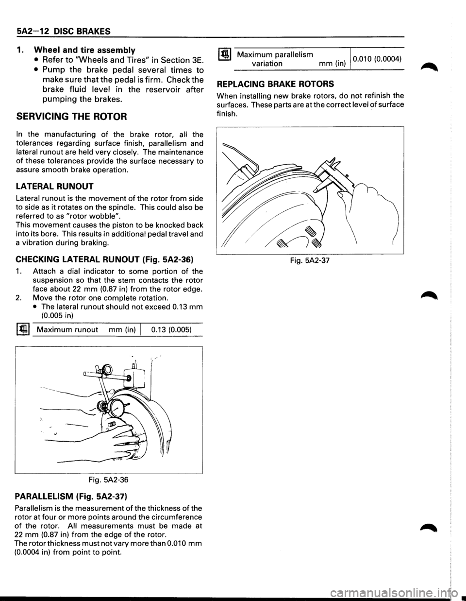
CHECKING LATERAL RUNOUT (Fig. 5A2-36)
1. Attach a dial indicator to some portion of the
suspension so
that the stem contacts the rotor
face about 22 mm (0.87 in) from the rotor edge.
2. Move the rotor one complete rotation.
• The lateral runout should not exceed 0.13 mm
(0.005 in)
~~~ Maximum runout mm (in) I 0.13 (0.005)
Fig. 5A2-36
PARALLELISM (Fig. 5A2-37)
Parallelism is the measurement of the thickness of the
rotor at
four or more points around the circumference
of the rotor. All measurements must be made at
22 mm (0.87 in) from the edge of the rotor.
The rotor thickness
must not vary more than 0.010 mm
(0.0004 in) from point to point.
Maximum parallelism variation mm (in) 0
·01 0 (0.000 4
)
REPLACING BRAKE ROTORS
When installing new brake rotors, do not refinish the
surfaces. These parts are at the correct
level of surface
finish.
Fig. 5A2-37