power steering fluid ISUZU TROOPER 1995 User Guide
[x] Cancel search | Manufacturer: ISUZU, Model Year: 1995, Model line: TROOPER, Model: ISUZU TROOPER 1995Pages: 1928
Page 142 of 1928
381 - 4 POWER STEERING GEAR AND PUMP
ON-VEHICLE SERVICE
MAINTENANCE
The hydraulic system should be kept clean and fluid
level in the reservoir should be checked at regular
intervals
and fluid added when required. Refer to
"MAINTENANCE AND LUBRICATION" in section OB
ofthe manual for type offluid to be used and intervals
for filling.
If the system contains some dirt, flush it as detailed
later
in this section. If it is exceptionally dirty, both the
pump and the gear must be completely disassembled
before further usage.
All tubes, hoses, and fittings should be inspected for
leakage at regular intervals. Fittings must be tight.
Make sure the clips, clamps and supporting tubes and
hoses are in
place and properly secured.
Power steering hoses and lines must not be twisted,
kinked or tightly bent. Air in the system will cause
spongy action and noisy operation. When a hose is
disconnected
or when fluid is lost, for any reason, the
system must be bled after refilling. Refer to "Bleeding
the Power Steering System" in this section.
FLUID LEVEL
1. Run the engine until the power steering fluid
reaches normal operating temperature, about
55°C (130°F), then shut the engine off.
2. Check the level of fluid in the reservoir.
3. If the fluid level is low, add power steering fluid
as specified in "MAINTENANCE AND LUBRI
CATION" in Section OB to the proper level and
install the receiver cap.
4. When checking the fluid level after the steering
system has been serviced,
air must be bled from
the system. Refer to "Bleeding the Power
Steering
System" in this section.
BLEEDING THE POWER STEERING
SYSTEM
When a power steering pump or gear has been
installed, or an oil line has been disconnected, the air
that has entered the system must be bled out before
the vehicle is operated. If air is allowed to remain in
the power steering fluid system, noisy and
unsatisfactory operation of the system may result.
BLEEDING PROCEDURE
When bleeding the system, and any time fluid is
added
to the power steering system, be sure to use
only power steering fluid as specified in
"MAINTENANCE AND LUBRICATION" in section OB.
1. Fill the pump fluid reservoir to the proper level
and let the fluid settle for at least two minutes.
2. Start the engine and let it run for a few seconds.
Do
not turn the steering wheel. Then turn the
engine off.
3. Add fluid if necessary.
4. Repeat the above procedure until the fluid level
remains constant after running the engine.
5. Raise the front end of the vehicle so that the
wheels are off the ground.
6. Start the engine. Slowly turn the steering wheel
right and left, lightly contacting the wheel stops.
7. Add power steering fluid if necessary.
8. Lower the vehicle and turn the steering wheel
slowly from lock to lock.
9. Stop the engine. Check the fluid level and refill
as required.
10.
If the fluid is extremely foamy, allow the vehicle
to stand a few minutes and repeat the above
procedure.
~ INSPECT
• Belt for tightness.
• Pulley for looseness or damage. The pulley
should not wobble with the engine running.
• Hoses so they are not touching any other parts
of the vehicle.
• Fluid level
and fill to the proper level.
FLUSHING THE POWER STEERING
SYSTEM
1. Raise the front end of the vehicle off the ground
until the wheels are free to turn.
2. Remove the fluid return line at the pump inlet
connector and plug the connector port on the
pump.
Position the line toward a large container to
catch the draining fluid.
3. While running the engine at idle, fill the reservoir
with new power steering fluid. Turn the steering
wheel in both directions. DO NOT contact wheel
stops or hold the wheel in a corner, or fluid will
stop and the pump will be in pressure relief mode.
A sudden
overflow from the reservoir may
develop if the wheel is held at a stop.
4. Install all the lines and hoses. Fill the system with
new power steering fluid and bleed the system
as described in "Bleeding The Power Steering
System". Operate the engine for about 15
minutes.
Remove the
pump return line at the pump inlet
and plug the connection on the pump. While
refilling the reservoir, check the draining fluid for
contamination. If foreign material is still evident,
replace all lines, disassemble and clean or replace
the power steering system components. Do not
re-use any drained power steering fluid.
~
~
Page 149 of 1928
![ISUZU TROOPER 1995 User Guide (1!] INSPECTION AND REPAIR
Inspect the following parts for wear, damage or any
other abnormal conditions.
• Bearing
• Ball-nut and valve housing
• Sector shaft
• Top cover
• Gear](/img/61/57183/w960_57183-148.png "ISUZU TROOPER 1995 User Guide (1!] INSPECTION AND REPAIR
Inspect the following parts for wear, damage or any
other abnormal conditions.
• Bearing
• Ball-nut and valve housing
• Sector shaft
• Top cover
• Gear")
(1!] INSPECTION AND REPAIR
Inspect the following parts for wear, damage or any
other abnormal conditions.
• Bearing
• Ball-nut and valve housing
• Sector shaft
• Top cover
• Gear box
• Needle bearing
• Dust seal
• Seal ring
• Gasket
Ball-nut rotation (fig. 381-18)
Hold the ball nut and valve housing assembly vertically
and see
if the ball-nut lowers by turning smoothly. If
the ball-nut does not lower smoothly, check the worm
shaft for bending and foreign matter.
NOTE:
When testing the ball nut and valve housing assembly,
do not let it travel all the way to the end of worm shaft,
or damage to the ball tubes will result.
• Check sector shaft outside diameter (Fig. 381-
19).
~~~ Limit mm (in) 31.7 (1.25)
Fig. 3B1-18
Fig. 3B1-19
POWER STEERING GEAR AND PUMP 381-11
Seal ring setting (fig. 381-20)
8.
~·
Note the setting direction. Always install a
new part.
Apply a thin coat of power steering fluid to lip of
each part.
Dust seal setting (Fig. 381-20)
r=l • Note the setting direction. Always install a
1.=.1 new part.
l<=l()l • Apply a thin coat of power steering fluid to lip of
each part.
Dust seal
Fig. 3B1-20
Gasket setting (fig. 381-21)
1 .. 1• Note the setting direction.
a:;::::;::] • Apply a thin coat of power steering fluid to lip of
D each part.
Fig.
3B1-21
Page 150 of 1928
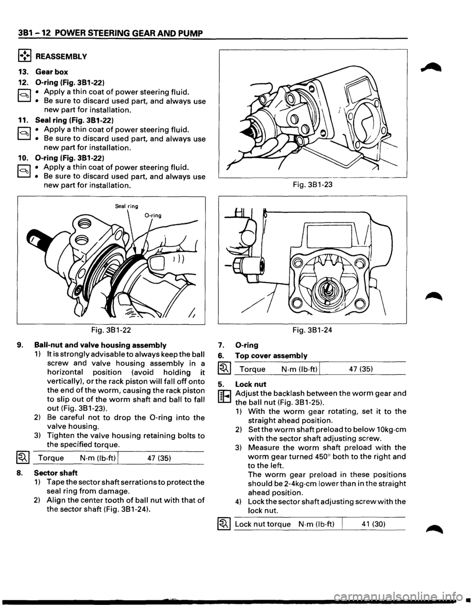
381 -12 POWER STEERING GEAR AND PUMP
l•!+l REASSEMBLY
13. Gear box
12.
0-ring (fig. 381-22)
r:::;:, • Apply a thin coat of power steering fluid.
D • Be sure to discard used part, and always use
new part for installation.
11. Seal ring (fig. 381-22)
r:::;:, • Apply a thin coat of power steering fluid.
D • Be sure to discard used part, and always use
new part for installation.
10.
0-ring (fig. 381-22)
r:::;:, • Apply a thin coat of power steering fluid.
D • Be sure to discard used part, and always use
new part for installation.
Seal ring
Fig. 3B1-22
9.
Ball-nut and valve housing assembly
1) It is strongly advisable to always keep the ball
screw and valve housing assembly in a
horizontal position (avoid holding it
vertically), or the rack piston will fall off onto
the end of the worm, causing the rack piston
to slip out of the worm shaft and ball to fall
out (Fig. 3B1-23).
2) Be careful not to drop the 0-ring into the
valve housing.
3) Tighten the valve housing retaining bolts to
the specified torque.
~~~ Torque N·m (lb.ft) I 47 (35)
8. Sector shaft
1) Tape the sector shaft serrations to protect the
seal ring from damage.
2) Align the center tooth of ball nut with that of
the sector shaft (Fig. 3B1-24). Fig.
3B1-23
Fig. 3B1-24
7. 0-ring
6. Top cover assembly
~~~ Torque N-m (lb·ftl I 47 (35)
5. Lock nut
r:cJ Adjust the backlash between the worm gear and
L:D the ball nut (Fig. 3B1-25).
1) With the worm gear rotating, set it to the
straight ahead position.
2) Set the worm shaft preload to below 1 Okg-cm
with the sector shaft adjusting screw.
3) Measure the worm shaft preload with the
worm gear turned 450° both to the right and
to the left.
The worm gear preload in these positions
should be 2-4kg-cm lower than in the straight
ahead position.
4) Lock the sector shaft adjusting screw with the
lock nut.
~~~ Lock nut torque N-m (lb·ft) I 41 (30)
•
Page 151 of 1928
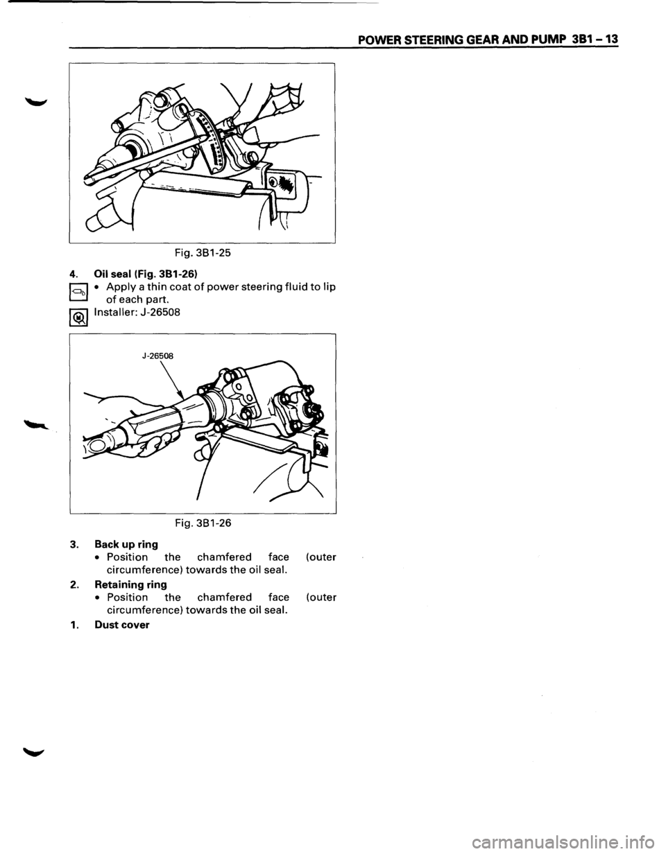
Fig. 381-25
4. Oil seal (Fig. 381-26)
~ • Apply a thin coat of power steering fluid to lip
D of each part.
l®..llnstaller: J-26508
J-26508
Fig. 381-26
3. Back up ring
• Position the chamfered face (outer
circumference) towards the oil seal.
2. Retaining ring
• Position the chamfered face (outer
circumference) towards the oil seal.
1. Dust cover
POWER STEERING GEAR AND PUMP 381 -13
Page 153 of 1928
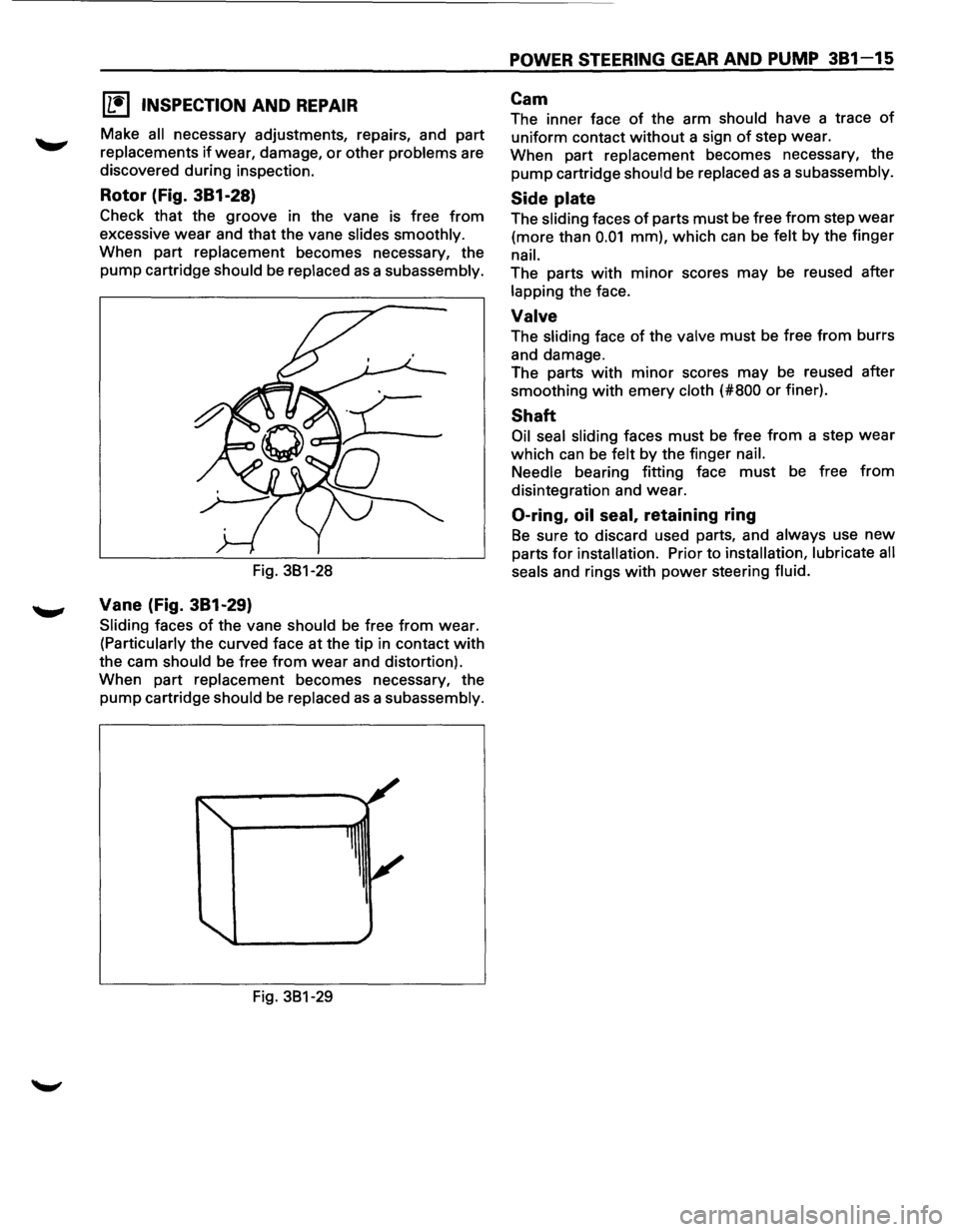
[1!) INSPECTION AND REPAIR
Make all necessary adjustments, repairs, and part
replacements
if wear, damage, or other problems are
discovered during inspection.
Rotor (Fig. 381-28)
Check that the groove in the vane is free from
excessive wear and that the vane slides smoothly.
When part replacement becomes necessary, the
pump cartridge
should be replaced as a subassembly.
Fig. 381-28
Vane (Fig. 381-29)
Sliding faces of the vane should be free from wear.
(Particularly the curved face at the tip in contact with
the cam should be free from wear and distortion).
When part
replacement becomes necessary, the
pump cartridge should be replaced as a subassembly.
Fig. 381-29
POWER STEERING GEAR AND PUMP 381-15
Cam
The inner face of the arm should have a trace of
uniform contact without a sign of step wear.
When part
replacement becomes necessary, the
pump cartridge should be replaced as a subassembly.
Side plate
The sliding faces of parts must be free from step wear
(more than 0.01 mm), which can be felt by the finger
nail.
The parts with minor scores may be reused after
lapping the face.
Valve
The sliding face of the valve must be free from burrs
and damage.
The parts
with minor scores may be reused after
smoothing
with emery cloth (#800 or finer).
Shaft
Oil seal sliding faces must be free from a step wear
which can be felt by the finger nail.
Needle
bearing fitting face must be free from
disintegration and wear.
0-ring, oil seal, retaining ring
Be sure to discard used parts, and always use new
parts for installation. Prior to installation, lubricate all
seals
and rings with power steering fluid.
Page 155 of 1928
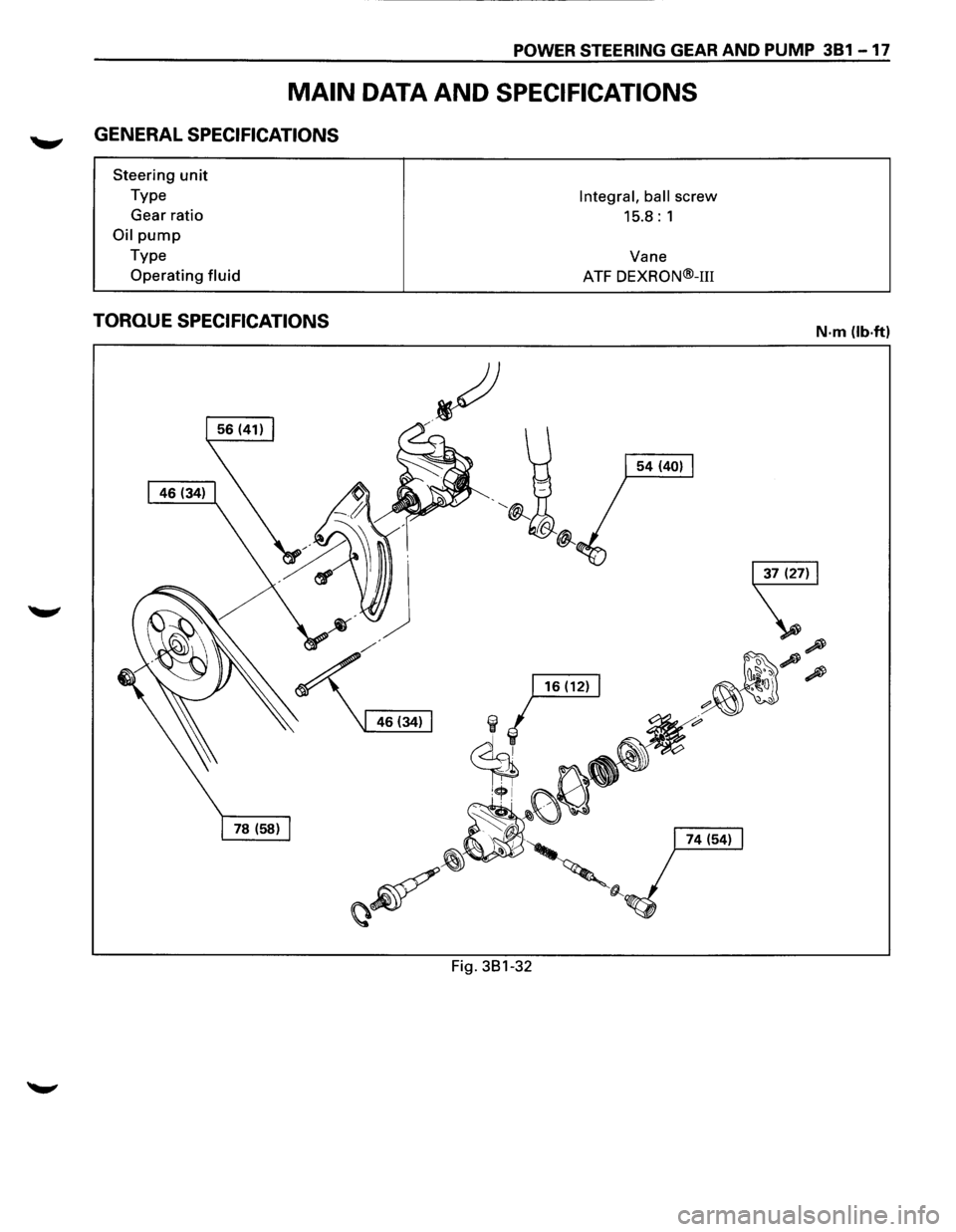
POWER STEERING GEAR AND PUMP 381-17
MAIN DATA AND SPECIFICATIONS
GENERAL SPECIFICATIONS
Steering unit
Type
Gear ratio
Oil pump
Type
Operating
fluid
TORQUE SPECIFICATIONS
Fig. 381-32
Integral, ball screw
15.8: 1
Vane
ATF
DEXRON®-m
N·m (lb.ft)
Page 1219 of 1928
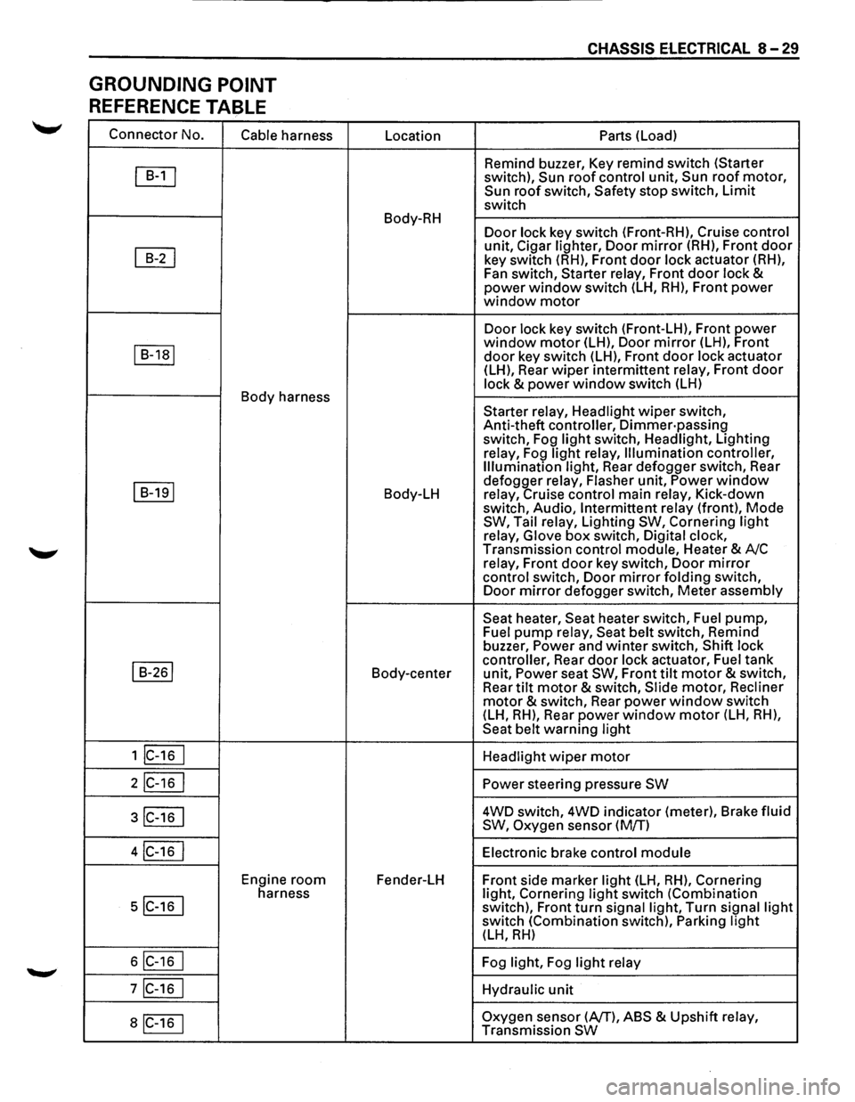
GROUNDING POINT
REFERENCE TABLE
Connector No.
Cable harness
~
~
I B-1a1
Body harness
I B-191
I B-261
1 lc-16 I
2IC-16 I
3IC-16 I
4IC-16 I
Engine room
5IC-16 I
harness
6IC-16 I
7IC-16 I
aiC-16 1
Location
Body-RH
Body-LH
Body-center
Fender-LH
CHASSIS ElECTRICAL 8-29
Parts (Load)
Remind buzzer, Key remind switch (Starter
switch),
Sun roof control unit, Sun roof motor, Sun roof switch, Safety stop switch, Limit
switch
Door lock key switch (Front-RH), Cruise control
unit, Cigar lighter, Door mirror (RH), Front door
key switch (RH), Front door lock actuator (RH),
Fan switch, Starter relay, Front
door lock & power window switch (LH, RH), Front power window motor
Door lock key switch (Front-LH), Front power window motor (LH), Door mirror (LH), Front
door key switch (LH), Front door lock actuator
(LH), Rear wiper intermittent relay, Front door
lock & power window switch (LH)
Starter relay, Headlight
wiper switch,
Anti-theft controller,
Dimmer·passing switch, Fog light switch, Headlight, Lighting
relay, Fog
light relay, Illumination controller,
Illumination light, Rear defogger switch, Rear
defogger relay, Flasher unit,
Power window relay, Cruise control main relay, Kick-down
switch, Audio, Intermittent relay (front), Mode SW, Tail relay, Lighting SW, Cornering light
relay, Glove box switch, Digital clock,
Transmission control module, Heater & A/C
relay, Front
door key switch, Door mirror
control switch, Door mirror folding switch,
Door mirror defogger switch, Meter assembly
Seat heater, Seat heater switch, Fuel pump, Fuel pump relay, Seat belt switch, Remind
buzzer, Power and winter switch, Shift lock
controller, Rear
door lock actuator, Fuel tank
unit, Power seat SW, Front tilt motor & switch,
Rear tilt motor & switch, Slide motor, Recliner
motor & switch, Rear power window switch
(LH, RH), Rear power window motor (LH, RH),
Seat belt warning light
Headlight
wiper motor
Power steering pressure SW
4WD switch, 4WD indicator (meter), Brake fluid
SW, Oxygen sensor (M/T)
Electronic brake control
module
Front side marker light (LH, RH), Cornering
light, Cornering light switch (Combination
switch), Front turn signal light, Turn signal light switch (Combination switch), Parking light (LH, RH)
Fog light, Fog light relay
Hydraulic
unit
Oxygen sensor (AfT), ABS & Upshift relay,
Transmission SW