service indicator ISUZU TROOPER 1995 User Guide
[x] Cancel search | Manufacturer: ISUZU, Model Year: 1995, Model line: TROOPER, Model: ISUZU TROOPER 1995Pages: 1928
Page 795 of 1928
DRIVEABILITV AND EMISSIONS 6E2-99
SECTION C
COMPONENTS SYSTEMS
CAUTION
When fasteners are removed, always reinstall them at the same location from which they were removed. If a
fastener needs
to be replaced, use the correct part number fastener for that application. If the correct part number
fastener is not available, a fastener of equal size and strength (or stronger) may be used. Fasteners that are not
reused, and those requiring thread locking compound will be called out. The correct torque value must be used
when installing fasteners that require it. If the above conditions are not followed, parts or system damage could
result.
Section
"C" provides information on the following:
• General description of components and sub-systems.
• On-vehicle service.
• Part names and group numbers.
• Diagnostic charts. These include a functional check of the system as well as diagnosis of any problem found in
the functional check.
For locations
of components, wiring diagrams, and engine control module terminal and view, refer to the front of
"Engine Components/Wiring Diagrams/Diagnostic Charts", Section "A".
Refer to the following sections for the appropriate sub-system information:
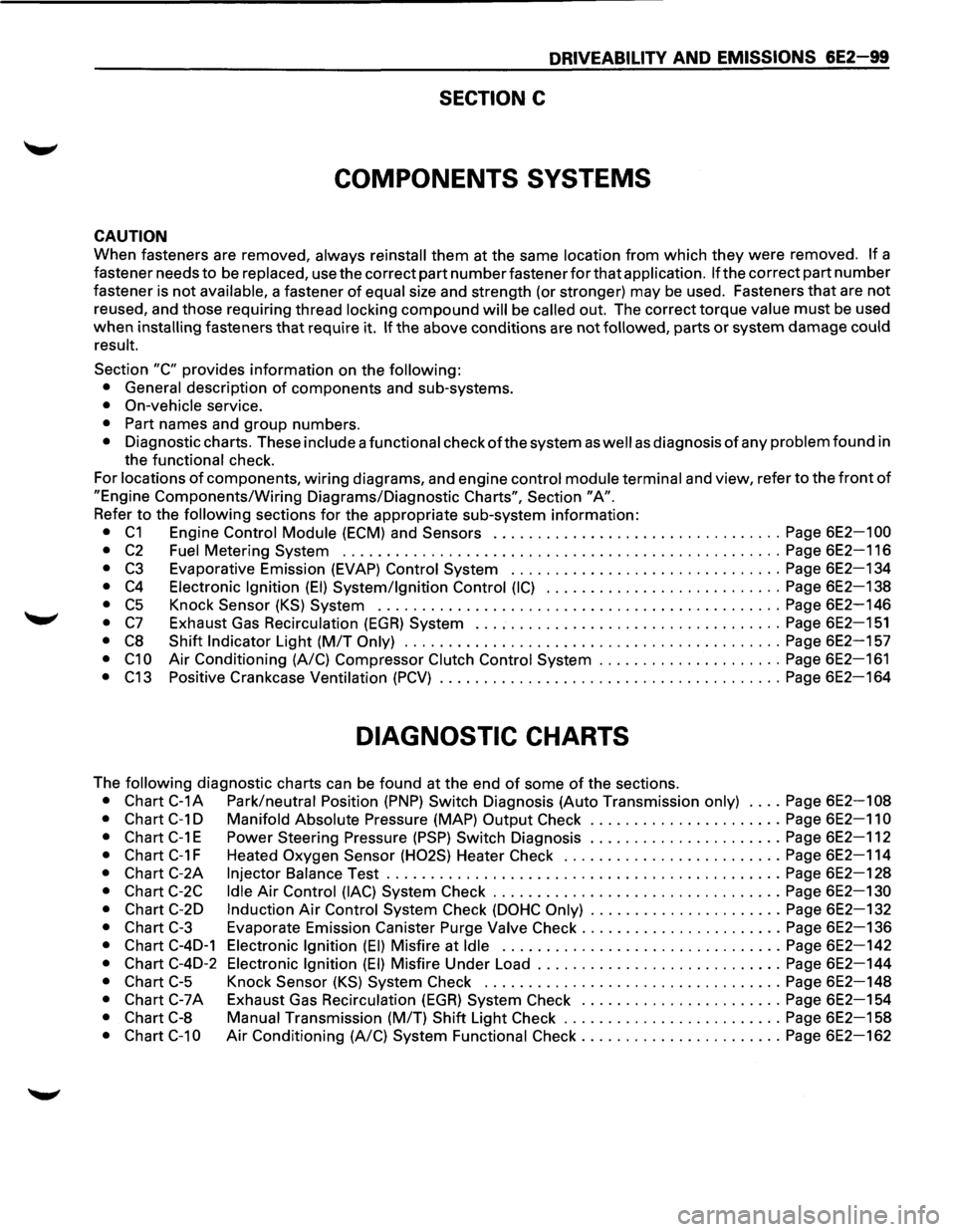
• C1 Engine Control Module (ECM) and Sensors ................................. Page 6E2-1 00
•
C2 Fuel Metering System .................................................. Page 6E2-116
• C3 Evaporative Emission (EVAP) Control System ............................... Page 6E2-134
• C4 Electronic Ignition (EI) System/Ignition Control (IC) ........................... Page 6E2-138
• C5 Knock Sensor (KS) System .............................................. Page 6E2-146
• C7 Exhaust Gas Recirculation (EGR) System ................................... Page 6E2-151
• C8 Shift Indicator Light (M/T Only) ........................................... Page 6E2-157
• C1 0 Air Conditioning (A/C) Compressor Clutch Control System ..................... Page 6E2-161
• C13 Positive Crankcase Ventilation (PCV) ....................................... Page 6E2-164
DIAGNOSTIC CHARTS
The following diagnostic charts can be found at the end of some of the sections.
• Chart C-1A Park/neutral Position (PNP) Switch Diagnosis (Auto Transmission only) .... Page 6E2-108
• Chart C-1 D Manifold Absolute Pressure (MAP) Output Check ...................... Page 6E2-11 0
•
Chart C-1 E Power Steering Pressure (PSP) Switch Diagnosis ...................... Page 6E2-112
• Chart C-1 F Heated Oxygen Sensor (H02S) Heater Check ......................... Page 6E2-114
• Chart C-2A Injector Balance Test ............................................. Page 6E2-128
• Chart C-2C Idle Air Control (lAC) System Check ................................. Page 6E2-130
• Chart C-2D Induction Air Control System Check (DOHC Only) ...................... Page 6E2-132
• Chart C-3 Evaporate Emission Canister Purge Valve Check ....................... Page 6E2-136
• Chart C-4D-1 Electronic Ignition (EI) Misfire at Idle ................................ Page 6E2-142
• Chart C-4D-2 Electronic Ignition (EI) Misfire Under Load ............................ Page 6E2-144
• Chart C-5 Knock Sensor (KS) System Check .................................. Page 6E2-148
• Chart C-7A Exhaust Gas Recirculation (EGR) System Check ....................... Page 6E2-154
• Chart C-8 Manual Transmission (MIT) Shift Light Check ......................... Page 6E2-158
• Chart C-1 0 Air Conditioning (A/C) System Functional Check ....................... Page 6E2-162
Page 796 of 1928
6E2-100 DRIVEABILITY AND EMISSIONS
SECTION C1
ENGINE CONTROL MODULE (ECM) & SENSORS
CONTENTS
General Description ...................... 6E2-1 00
Engine Control Module (ECM) .............. 6E2-100
Engine Control Module (ECM) Function ....... 6E2-1 00
Information Sensors ..................... 6E2-1 01
Engine Coolant Temperature (ECT) Sensor ... 6E2-101
Intake Air Temperature (IAT) Sensor ........ 6E2-101
Heated Oxygen Sensor (H02S) ........... 6E2-101
Throttle Position
(TP) Sensor ............. 6E2-102
Manifold Absolute Pressure (MAP) Sensor ... 6E2-102
Vehicle Speed Sensor (VSS) ............. 6E2-102
Knock Sensor (KS) (DOHC ONLY) .......... 6E2-102
Air Conditioning (A/C) Request Signal ...... 6E2-1 02
Power Steering Pressure (PSP) Switch ...... 6E2-1 02
Park/Neutral Position (PNP) Switch
(Auto only)
........................ 6E2-1 03 Diagnosis ............................. 6E2-1 03
Engine Control Module (ECM) .............. 6E2-1 03
Electrically Erasable Programmable Read
Only Memory ........................ 6E2-1 03
Engine Control Module (ECM) Inputs ....... 6E2-103
Engine Coolant Temperature (ECT) Sensor ... 6E2-1 04
Intake Air Temperature (IAT) Sensor ........ 6E2-1 04
Heated Oxygen Sensor
(H02S) ........... 6E2-1 04
Throttle Position
(TP) Sensor ............. 6E2-1 04
Manifold Absolute Pressure (MAP) Sensor
... 6E2-1 04
Vehicle Speed Sensor (VSS) ............. 6E2-1 04
Air Conditioning (A/C) Request Signal
Power Steering Pressure
(PSP) Switch ..... .
Crankshaft Position
(CKP) Reference Signal ..
Park/Neutral Position (PNP) Switch ....... .
Knock Sensor
(KS) ................... .
On-Vehicle Service ..................... .
Engine Control Module
(ECM) ............ .
Engine Control Module
(ECM) Replacement ..
Engine Coolant Temperature (ECT) Sensor ... .
Intake Air Temperature (IAT) Sensor ........ .
Heated Oxygen Sensor
(H02S) ............ .
Throttle Position
(TP) Sensor ............. .
Manifold Absolute Pressure (MAP) Sensor
.... .
Vehicle Speed Sensor
(VSS) ............. .
Power Steering Pressure
(PSP) Switch ...... .
Park/Neutral Position
(PNP) Switch ......... .
Chart C-1A Park/Neutral Position
(PNP)
Switch Diagnosis .................... .
Chart
C-1 D Manifold Absolute Pressure (MAP)
Output Check
...................... .
Chart
C-1 E Power Steering Pressure (PSP)
Switch Diagnosis .................... .
Chart
C-1 F Heated Oxygen Sensor (H02S)
Heater Check ....................... .
6E2-104
6E2-104
6E2-104
6E2-104
6E2-104
6E2-104
6E2-104
6E2-105
6E2-105
6E2-106
6E2-106
6E2-107
6E2-107
6E2-107
6E2-107
6E2-107
6E2-108
6E2-110
6E2-112
6E2-114
GENERAL DESCRIPTION
ENGINE CONTROL MODULE (ECM)
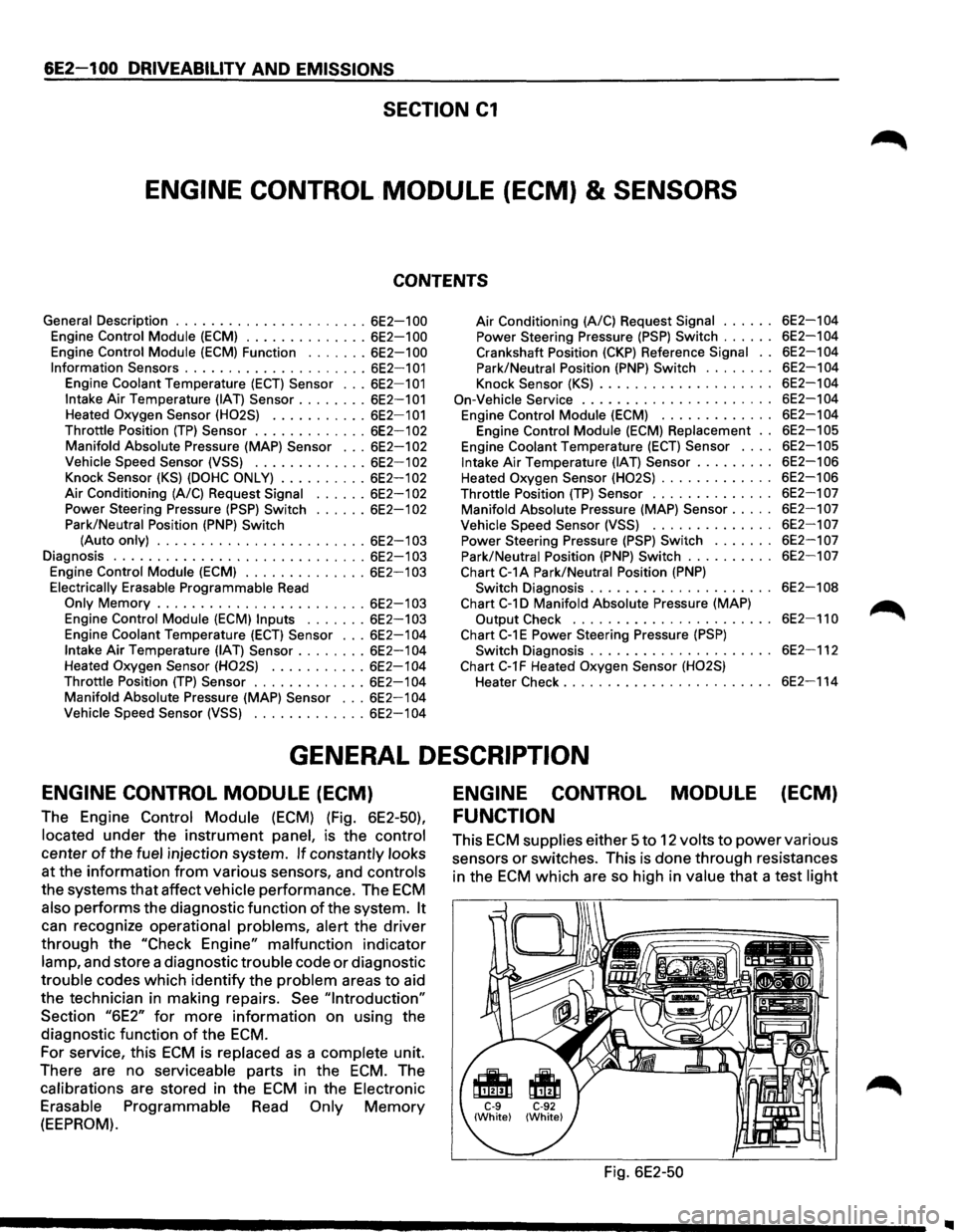
The Engine Control Module (ECM) (Fig. 6E2-50),
located under the instrument panel, is the control
center of the fuel injection system. If constantly looks
at the information from various sensors, and controls
the systems that affect vehicle performance. The ECM
also performs the diagnostic function of the system. It
can recognize operational problems, alert the driver
through the "Check Engine" malfunction indicator
lamp, and store a diagnostic trouble code or diagnostic
trouble codes which identify the problem areas to aid
the technician in making repairs.
See "Introduction"
Section "6E2" for more information on using the
diagnostic function
of the ECM.
For service, this ECM is replaced as a complete unit.
There are no serviceable parts in the
ECM. The
calibrations are stored in the
ECM in the Electronic
Erasable Programmable Read Only Memory
(EEPROM).
ENGINE CONTROL MODULE (ECM)
FUNCTION
This ECM supplies either 5 to 12 volts to power various
sensors
or switches. This is done through resistances
in the
ECM which are so high in value that a test light
Fig. 6E2-50
Page 799 of 1928
Park/Neutral Position (PNP) Switch (Auto Only)
The Park/Neutral position (PNP) switch indicates to the
Engine Control Module
(ECM) when the transmission
is in park, neutral
or drive. This information is used for
the exhaust gas recirculation, and the idle air control
valve operation.
NOTE:
• Vehicle
should not be driven with PNP switch
disconnected,
as idle quality will be affected and a
possible false diagnostic trouble code
(DTC) 24
(vehicle speed sensor).
DRIVEABILITY AND EMISSIONS 6E2-103
See DIAGNOSIS AND GENERAL SERVICE Section for
more information on the PNP switch. The PNP switch is
part
of the neutral/start and backup light switch
assembly mounted on the transmission.
See CHART C-
1 A for PNP switch check.
DIAGNOSIS
To read the DTC(s), use a "Scan tool" or ground the
diagnostic test terminal,
with the engine not running
and the ignition
"ON". The "Check Engine" malfunction
indicator lamp
will flash DTC 12 three times and then
flash each
DTC stored in memory three times. All
DTC(s) stored in memory will have been read when
DTC 12 is flashed again.
No new
DTC(s) can be stored when in the diagnostics
test mode (diagnostics lead grounded). This
eliminates confusion while the system is being
serviced.
To clear the
DTC(s) from memory:
• Ignition "OFF".
•
Disconnect main fuse located in the under hood
fuse/relay center near the battery.
Since the ECM can have a failure which may affect only
one circuit, following the diagnostic procedures in this
section
will determine which circuit has a problem and
where
it is.
If a diagnostic chart indicates thatthe ECM connections
or ECM is the cause of a problem, and the ECM is
replaced,
but does not correct the problem, one of the
following may be the reason.
• There is a problem with the ECM terminal
connections-The diagnostic chart will say ECM
connections or ECM. The terminals may have to
be removed from the connector in order to check
them properly.
• The ECM is not correct for the Vehicle-Ane
incorrect
ECM may cause a malfunction and may
set a DTC.
• The problem is intermittent -This means that
the problem is
not present at the time the system is
being checked.
In this case, refer to the
"Symptoms" portion of the manual and make a
careful physical inspection
of all portions of the
system involved.
• Shorted solenoid, relay coil, or harness
Solenoid and relays are turned "ON" and "OFF" by
the
ECM, using internal electronic switches called
"drivers".
Each driver is part of a group of four,
called "quad-drivers". Failure of one driver can
damage any other driver in the set. A
shorted solenoid, relay coil, or harness in a l-EFT
SHCI
computer will not damage the ECM, but will
cause the circuit and controlled component to be
inoperative. When the circuit fault is not present or
has been repaired, the "quad-driver" will again
operate in a normal manner due to its fault
protected design. If a fault has been repaired in a
circuit controlled by a "quad-driver", the original
ECM should be reinstalled and the circuit checked
for proper operation. ECM replacement will not be
necessary if the repaired circuit or component now
operates correctly.
J 34636 or BT-8405 testers or equivalent provide a fast,
accurate means
of checking for a shorted coil or a short
to battery positive voltage.
• The replacement ECM may be faulty-After the
ECM is replaced, the system should be re-checked
for proper operation. If the diagnostic chart again
indicates the
ECM is the problem, substitute a
known good
ECM. Although this is a rare
condition,
it could happen.
ENGINE CONTROL MODULE (ECM)
A faulty ECM will be determined in the diagnostic
charts.
ELECTRONICALL V ERASABLE
PROGRAMMABLE READ
ONL V MEMORY
A faulty electrically erasable programmable read only
memory, which is part of the ECM, will set a DTC 51.
ENGINE CONTROL MODULE (ECM)
INPUTS
All of the sensors and input switches can be diagnosed
by the use
of "Scan tool".
Following is a short description of how the sensors and
switches can be diagnosed by the use
"Scan tool". The
"Scan tool" can also be used to compare the values for
a normal running engine with the engine you're
diagnosing.
Page 801 of 1928
wcAUTION:
' • When replacing the production Engine Control
Module
(ECM) with a service ECM (controller),
it is important to transfer the broadcast
diagnostic
trouble code and production ECM
number to the service ECM label. Please do not
record on ECM cover. This will allow positive
identification
of ECM parts throughout the
service
life of the vehicle.
DRIVEABILITV AND EMISSIONS 6E2-1 05
\fCAUTION:
' • To prevent internal ECM damage, the ignition
must be
"OFF" when disconnecting or
reconnecting power
to ECM (for example;
battery cable, ECM pigtail, ECM fuse, jumper
cables etc.)
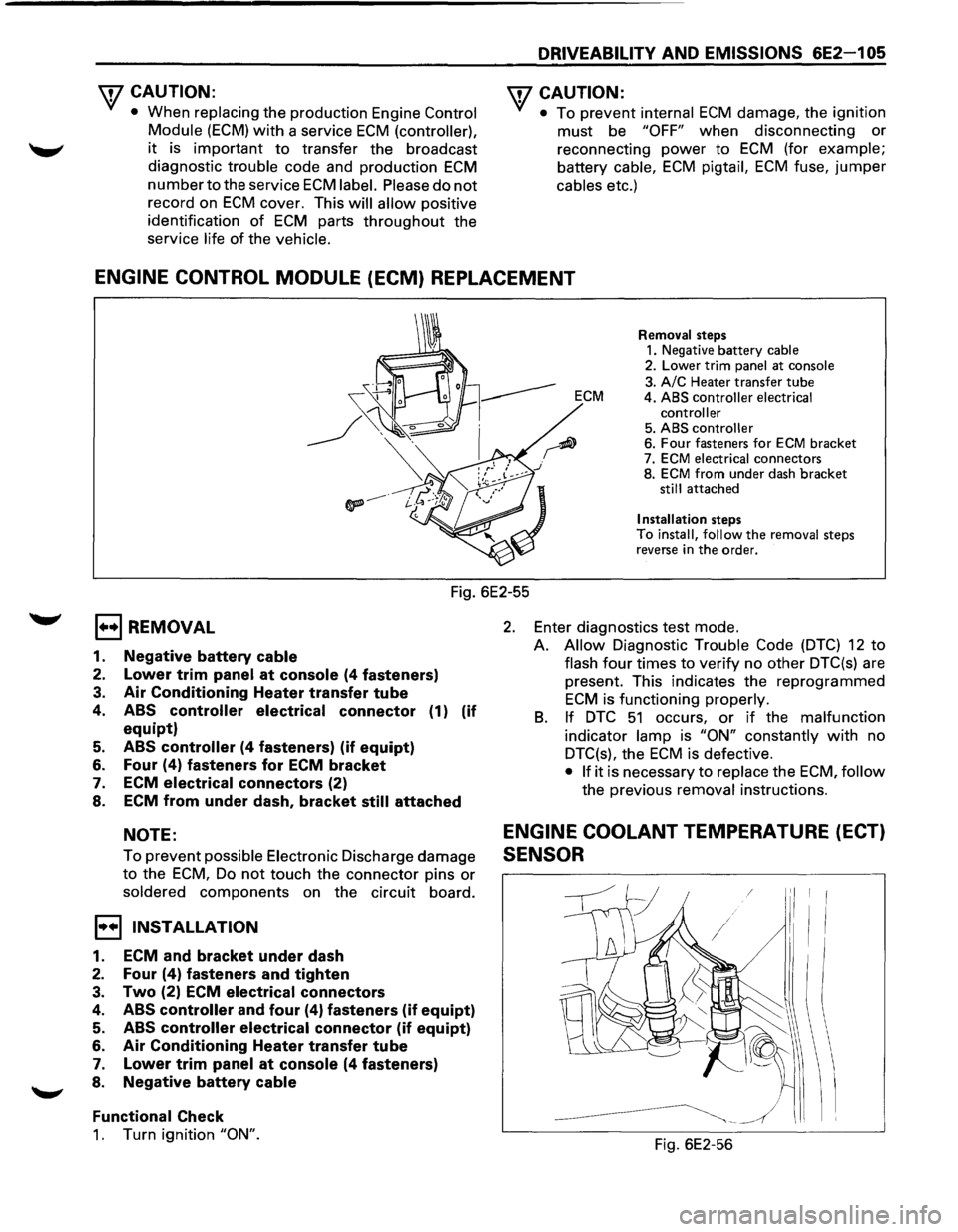
ENGINE CONTROL MODULE (ECM) REPLACEMENT
Removal steps 1. Negative battery cable 2. Lower trim panel at console
3. A/C Heater transfer tube ECM 4. ABS controller electrical
controller
5. ABS controller 6. Four fasteners for ECM bracket
7. ECM electrical connectors
8. ECM from under dash bracket still attached
Installation steps To install, follow the removal steps
reverse in the order.
Fig. 6E2-55
EJ REMOVAL
1. Negative battery cable
2. Lower trim panel at console (4 fasteners)
3. Air Conditioning Heater transfer tube
4. ABS controller electrical connector (1) (if
equipt)
5. ABS controller (4 fasteners) (if equipt)
6. Four (4) fasteners for ECM bracket
7. ECM
electrical connectors (2)
8. ECM from under dash, bracket
still attached
NOTE:
To prevent possible Electronic Discharge damage
to the ECM, Do not touch the connector pins or
soldered components on the circuit board.
I•+! INSTALLATION
1. ECM and bracket under dash
2. Four (4) fasteners and tighten
3. Two (2) ECM electrical connectors
4. ABS controller and four (4) fasteners (if equipt)
5. ABS controller electrical connector (if equipt)
6. Air Conditioning Heater transfer tube
7. Lower trim panel at console (4 fasteners)
8. Negative battery
cable
Functional
Check
1. Turn ignition "ON".
2. Enter diagnostics test mode.
A.
Allow Diagnostic Trouble Code (DTC) 12 to
flash four times to verify no other DTC(s) are
present. This indicates the reprogrammed
ECM is functioning properly.
B. If DTC 51 occurs, or if the malfunction
indicator lamp is "ON" constantly with no
DTC(s), the
ECM is defective.
• If it is necessary to replace the ECM, follow
the previous removal instructions.
ENGINE COOLANT TEMPERATURE (ECT)
SENSOR
Fig. 6E2-56
Page 835 of 1928
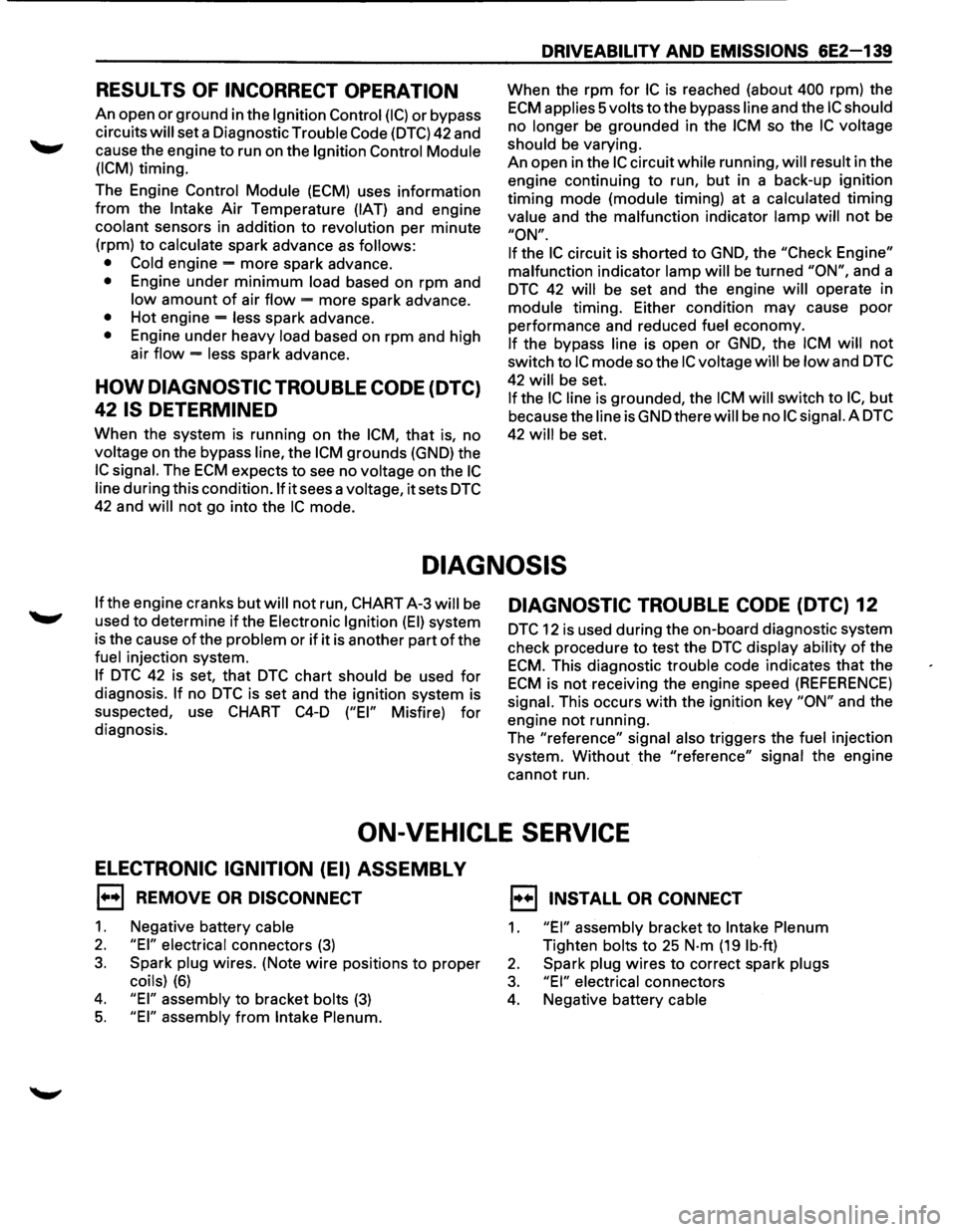
RESULTS OF INCORRECT OPERATION
An open or ground in the Ignition Control (I C) or bypass
circuits
will set a Diagnostic Trouble Code (DTC) 42 and
cause the engine
to run on the Ignition Control Module
(ICM)
timing.
The Engine
Control Module (ECM) uses information
from the Intake Air Temperature (IAT) and engine
coolant sensors in addition to revolution per minute
(rpm) to
calculate spark advance as follows:
• Cold
engine -more spark advance.
• Engine under minimum load based on rpm and
low amount of air flow = more spark advance.
• Hot engine = less spark advance.
• Engine under heavy load based on rpm and high
air
flow = less spark advance.
HOW DIAGNOSTIC TROUBLE CODE (DTC)
42 IS DETERMINED
When the system is running on the ICM, that is, no
voltage on the bypass line, the ICM grounds (GND) the
IC signal. The ECM expects to see no voltage on the IC
line during this condition.lf it sees a voltage, it sets DTC
42 and will not go into the IC mode.
DRIVEABILITY AND EMISSIONS 6E2-139
When the rpm for IC is reached (about 400 rpm) the
ECM applies 5 volts to the bypass line and the IC should
no longer be grounded in the ICM so the IC voltage
should
be varying.
An open in the
IC circuit while running, will result in the
engine continuing to run, but in a back-up
ig~it~on
timing mode (module timing) at a calculated t1mmg
value
and the malfunction indicator lamp will not be
"ON".
If
the IC circuit is shorted to GND, the "Check Engine"
malfunction
indicator lamp will be turned "ON", and a
DTC 42 will be set and the engine will operate in
module timing. Either condition may cause poor
performance and reduced
fuel economy.
If the bypass line is open or GND, the ICM will not
switch to IC mode so the IC voltage will be low and DTC
42 will be set.
If the IC line is grounded, the ICM will switch to IC, but
because the line isGNDtherewill be no ICsignai.A DTC
42 will be set.
DIAGNOSIS
If the engine cranks but will not run, CHART A-3 will be
used to determine if the Electronic Ignition (EI) system
is the cause
of the problem or if it is another part of the
fuel injection system.
If DTC 42 is set, that DTC chart should be used for
diagnosis. If no DTC is set and the ignition system is
suspected, use
CHART C4-D ("EI" Misfire) for
diagnosis.
DIAGNOSTIC TROUBLE CODE (DTC) 12
DTC 12 is used during the on-board diagnostic system
check procedure to test the
DTC display ability of the
ECM. This diagnostic trouble code indicates that the
ECM is not receiving the engine speed (REFERENCE)
signal. This occurs with the ignition key "ON" and the
engine not running.
The "reference"
signal also triggers the fuel injection
system.
Without the "reference" signal the engine
cannot run.
ON-VEHICLE SERVICE
ELECTRONIC IGNITION (EI) ASSEMBLY
1••1 REMOVE OR DISCONNECT
1. Negative battery cable
2. "EI" electrical connectors (3)
3. Spark plug wires. (Note wire positions to proper
coils) (6)
4. "EI" assembly to bracket bolts (3)
5. "EI" assembly from Intake Plenum.
1••1 INSTALL OR CONNECT
1. "EI" assembly bracket to Intake Plenum
Tighten bolts to 25 N·m (19 lb·ft)
2. Spark plug wires to correct spark plugs
3. "EI" electrical connectors
4. Negative battery cable
Page 859 of 1928
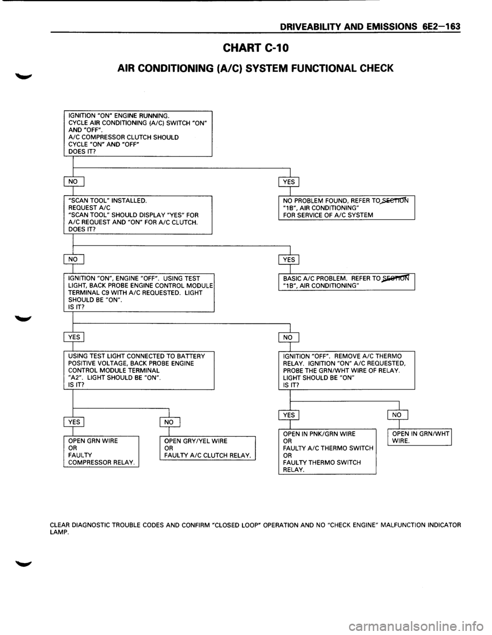
DRIVEABILITV AND EMISSIONS 6E2-163
CHART C-10
AIR CONDITIONING (A/C) SYSTEM FUNCTIONAL CHECK
IGNITION "ON" ENGINE RUNNING.
CYCLE AIR CONDITIONING (A/C) SWITCH "ON" AND "OFF". A/C COMPRESSOR CLUTCH SHOULD
CYCLE "ON" AND "OFF"
DOES IT?
$
$
"SCAN TOOL" INSTALLED.
NO PROBLEM FOUND, REFER TO)>e€TIO'N REQUEST A/C "1B", AIR CONDITIONING"
"SCAN TOOL" SHOULD DISPLAY "YES" FOR FOR SERVICE OF A/C SYSTEM A/C REQUEST AND "ON" FOR A/C CLUTCH.
DOES IT?
$
$
IGNITION "ON", ENGINE "OFF". USING TEST BASIC A/C PROBLEM. REFER TO~ LIGHT, BACK PROBE ENGINE CONTROL MODULE "1B", AIR CONDITIONING"
TERMINAL C9 WITH A/C REQUESTED. LIGHT
SHOULD BE "ON". IS IT?
$ $
USING TEST LIGHT CONNECTED TO BATTERY IGNITION "OFF". REMOVE A/C THERMO
POSITIVE VOLTAGE, BACK PROBE ENGINE RELAY. IGNITION "ON" A/C REQUESTED, CONTROL MODULE TERMINAL PROBE THE GRN/WHT WIRE OF RELAY. "A2". LIGHT SHOULD BE "ON". LIGHT SHOULD BE "ON" IS IT?
IS IT?
I
$ $
~ $ OPEN IN PNK/GRN WIRE I OPEN IN GRN/WHTJ OPEN GRN WIRE
OPEN GRY/YEL WIRE OR WIRE. OR OR FAULTY A/C THERMO SWITCH FAULTY FAULTY A/C CLUTCH RELAY. OR COMPRESSOR RELAY. FAULTY THERMO SWITCH RELAY.
CLEAR DIAGNOSTIC TROUBLE CODES AND CONFIRM "CLOSED LOOP" OPERATION AND NO "CHECK ENGINE" MALFUNCTION INDICATOR LAMP.
Page 861 of 1928
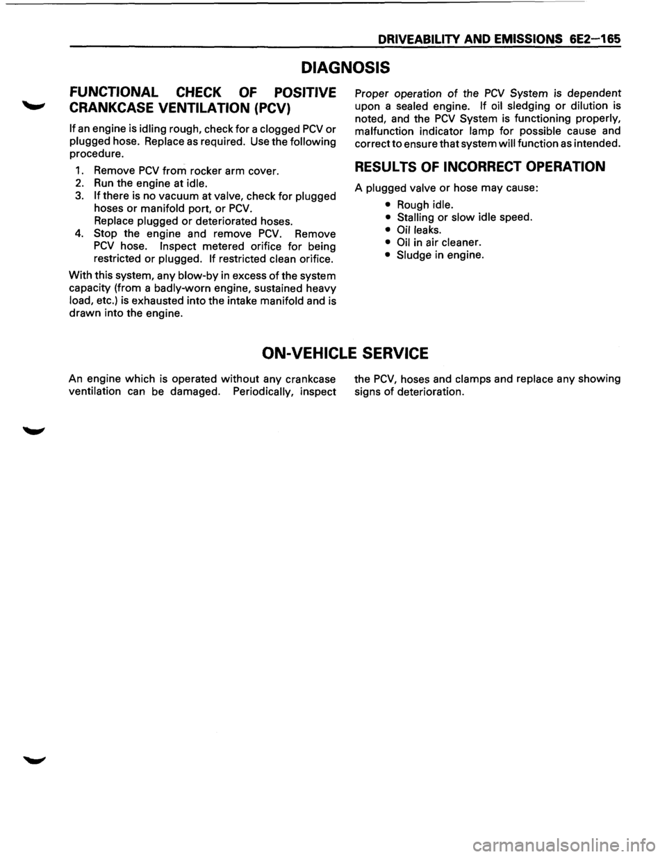
DRIVEABILITV AND EMISSIONS 6E2-165
DIAGNOSIS
FUNCTIONAL CHECK OF POSITIVE
CRANKCASE VENTILATION (PCV)
If an engine is idling rough, check for a clogged PCV or
plugged hose. Replace as required. Use the following
procedure.
1. Remove PCV from rocker arm cover.
2. Run the engine at idle.
3. If there is no vacuum at valve, check for plugged
hoses or manifold port, or PCV.
Replace plugged or deteriorated hoses.
4. Stop the engine and remove PCV. Remove
PCV hose. Inspect metered orifice for being
restricted or
plugged. If restricted clean orifice.
With this system, any
blow-by in excess of the system
capacity (from a
badly-worn engine, sustained heavy
load, etc.) is exhausted into the intake manifold and is
drawn into the engine. Proper
operation
of the PCV System is dependent
upon a
sealed engine. If oil sledging or dilution is
noted, and the PCV System is functioning properly,
malfunction
indicator lamp for possible cause and
correct to ensure that system
will function as intended.
RESULTS OF INCORRECT OPERATION
A plugged valve or hose may cause:
• Rough idle.
• Stalling
or slow idle speed.
• Oil leaks.
• Oil
in air cleaner.
• Sludge
in engine.
ON-VEHICLE SERVICE
An engine which is operated without any crankcase
ventilation can be damaged. Periodically, inspect the
PCV, hoses
and clamps and replace any showing
signs
of deterioration.
Page 873 of 1928
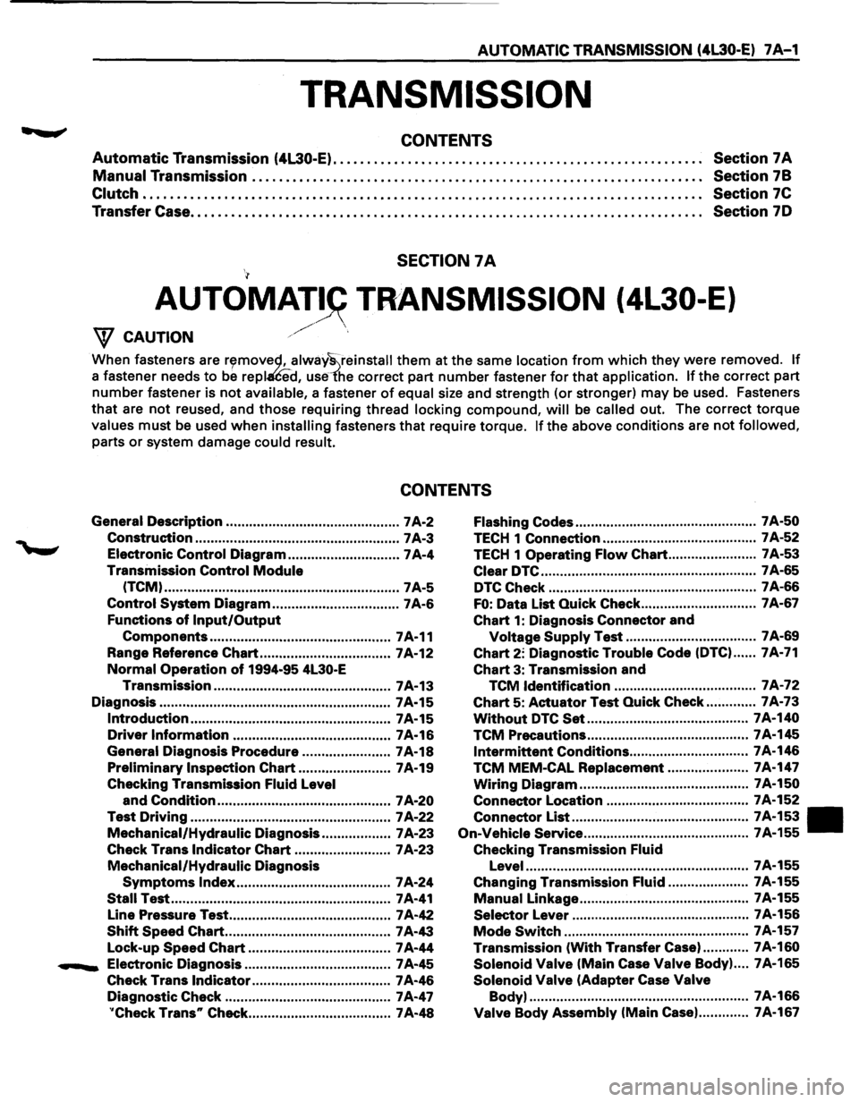
AUTOMATIC TRANSMISSION (4l30-E) 7 A-1
TRANSMISSION
CONTENTS
Automatic Transmission (4L30-E). . . . . . . . . . . . . . . . . . . . . . . . . . . . . . . . . . . . . . . . . . . . . . . . . . . . . . . Section 7 A
Manual Transmission . .
. . . . . . . . . . . . . . . . . . . . . . . . . . . . . . . . . . . . . . . . . . . . . . . . . . . . . . . . . . . . . . . . . Section
78
Clutch . . . . . . . . . . . . . . . . . . . . . . . . . . . . . . . . . . . . . . . . . . . . . . . . . . . . . . . . . . . . . . . . . . . . . . . . . . . . . . . . . . . Section 7C
Transfer Case. . . . . . . . . . . . . . . . . . . . . . . . . . . . . . . . . . . . . . . . . . . . . . . . . . . . . . . . . . . . . . . . . . . . . . . . . . . . Section 70
SECTION 7A
AUTOMAT~ TRANSMISSION (4L30-E)
/' W CAUTION ./
When fasteners are r~movec;l, alway~reinstall them at the same location from which they were removed. If
a fastener needs to be repl£ed, use1'he correct part number fastener for that application. If the correct part
number fastener is not available, a fastener of equal size and strength (or stronger) may be used. Fasteners
that are not reused, and those requiring thread locking compound, will be called out. The correct torque
values must be used when installing fasteners that require torque. If the above conditions are not followed,
parts or system damage could result.
CONTENTS
General Description ............................................. 7 A-2 Flashing Codes ............................................... 7 A-50
Construction ..................................................... 7 A-3 TECH 1 Connection ........................................ 7 A-52
Electronic Control Diagram ............................. 7A-4 TECH 1 Operating Flow Chart ....................... 7 A-53
Transmission
Control Module Clear DTC ........................................................ 7 A-65
(TCM) ............................................................. 7A-5 DTC Check ...................................................... 7 A-66
Control System Diagram ................................. 7 A-6 FO: Data List Quick Check .............................. 7A-67
Functions
of Input/Output Chart 1: Diagnosis Connector and
Components ............................................... 7A-11 Voltage Supply Test .................................. 7A-69
Range Reference
Chart .................................. 7A-12 Chart 2: Diagnostic Trouble Code (DTC) ...... 7A-71
Normal Operation of 1994-95 4L30-E Chart 3: Transmission and
Transmission .............................................. 7 A-13
TCM Identification ..................................... 7 A-72
Diagnosis ............................................................ 7A-15
Chart 5: Actuator Test Quick Check ............. 7A-73
Introduction .................................................... 7A-15 Without DTC Set .......................................... 7 A-140
Driver Information ......................................... 7 A-16 TCM Precautions .......................................... 7A-145
General Diagnosis Procedure ....................... 7A-18 Intermittent Conditions ............................... 7A-146
Preliminary Inspection Chart ........................ 7 A-19 TCM MEM-CAL Replacement ..................... 7A-147
Checking Transmission Fluid Level Wiring Diagram ............................................ 7A-150
and
Condition ............................................. 7 A-20 Connector Location
..................................... 7A-152
Test Driving .................................................... 7 A-22
Mechanical/Hydraulic Diagnosis .................. 7 A-23
Connector List .............................................. 7A-153 •
On-Vehicle
Service ........................................... 7A-155
Check Trans Indicator Chart ......................... 7 A-23 Checking Transmission Fluid
Mechanical/Hydraulic
Diagnosis Level .......................................................... 7A-155
Symptoms Index ........................................ 7A-24 Changing Transmission Fluid ..................... 7A-155
Stall Test ......................................................... 7 A-41 Manual Linkage ............................................ 7A-155
Line Pressure Test .......................................... 7 A-42
Selector Lever .............................................. 7 A-156
Shift Speed Chart ........................................... 7 A-43 Mode Switch ................................................ 7A-157
Lock-up
Speed Chart ..................................... 7 A-44 Transmission
(With Transfer Case). ........... 7A-160
....._ Electronic Diagnosis ...................................... 7 A-45 Solenoid Valve (Main Case Valve Body) .... 7A-165
Check Trans Indicator .................................... 7 A-46 Solenoid Valve (Adapter Case Valve
Diagnostic Check ........................................... 7 A-47 Body)
......................................................... 7A-166
''Check Trans" Check ..................................... 7 A-48 Valve Body Assembly (Main Case) ............. 7A-167
Page 920 of 1928
7 A-48 AUTOMATIC TRANSMISSION (4L30-E)
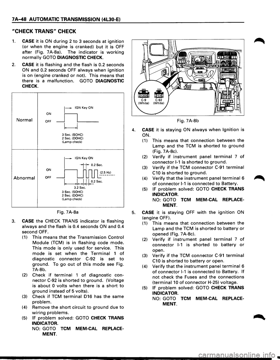
"CHECK TRANS" CHECK
1. CASE it is ON during 2 to 3 seconds at ignition
(or when the engine is cranked) but it is OFF
after (Fig. 7A-8a). The indicator is working
normally GOTO DIAGNOSTIC CHECK.
2. CASE it is flashing and the flash is 0.2 seconds
ON and 0.2 seconds OFF always when ignition
is on (engine cranked or not). This means that
there is a malfunction. GOTO DIAGNOSTIC
CHECK.
Normal
Abnormal
~-IGN Key ON
ON
II
OFF __j l___
~
3 Sec. (SOHC) 2 Sec. (OOHC) (Lamp check)
1-
IGN Key ON
il 0.2Sec.
oN 11 n n n ~~--s_ ~~)-_. OFF __j u u u l:
I. .I. .1.11. 0.2
Sec.
3.2 Sec. 3 Sec. (SOHC) 2 Sec. (OOHC) (Lamp check)
Fig. 7A-8b
4. CASE it is staying ON always when Ignition is
ON.
(1) This means that connection between the
Lamp and the TCM is shorted to ground
(Fig. 7 A-8c).
(2) Verify if instrument panel terminal 7 of
connector 1-1 is shorted to ground.
(3) Verify if the TCM connector C-91 terminal
C10 is shorted to ground.
(4) Verify that the instrument panel terminal 6
of connector 1-1 is connected to Battery.
(5) IF problem solved: GOTO CHECK TRANS
INDICATOR.
NO: GOTO TCM MEM-CAL REPLACE
MENT.
Fig. 7A-8a 5. CASE it is staying OFF with the ignition ON
(engine OFF). 3. CASE the CHECK TRANS indicator is flashing
always and the flash is 0.4 seconds ON and 0.4
second OFF.
(1) This means that the Transmission Control
Module (TCM) is in flashing code mode.
This mode is only used for service. This
mode is set when the Terminal 1 of
diagnostic connector C-92 is set to
ground. To go out of this mode see Fig.
7A-8b.
(2) Check
if terminal 1 of diagnostic con
nector C-92 is shorted to ground. (Voltage
is
about 0 volts when there is a short to
ground instead of 5 volts).
(3) Check if TCM terminal 016 has the same
problem.
(4) Remove the short circuit to ground due to
wiring problems.
(5) IF problem solved: GOTO CHECK TRANS
INDICATOR.
NO: GOTO TCM MEM-CAL REPLACE
MENT.
(1) This means that connection between the
Lamp and the TCM is shorted to battery or
opened (Fig. 7 A-8c).
(2) Verify if instrument panel terminal 7 of
connector 1-1 is shorted to battery or
open.
(3)
Verify if the TCM connector C-91 terminal
C1 0 is shorted to battery or open.
(4)
Verify that the instrument panel terminal 6
of connector 1-1 is connected to Battery. If
not check the Fuses and the connections
(terminal 10 of connector H-25) voltage.
(5) IF problem solved: GOTO CHECK TRANS
INDICATOR.
NO: GOTO TCM MEM-CAL REPLACE
MENT.
Page 1027 of 1928
... ......,.
AUTOMATIC TRANSMISSION (4L30-E) 7A-155
ON-VEHICLE SERVICE
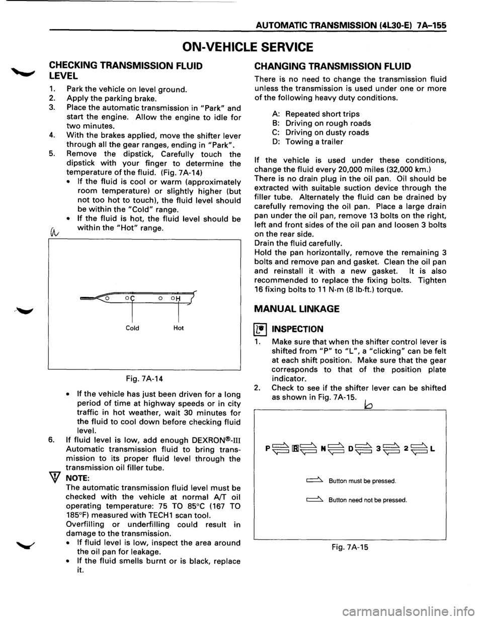
CHECKING TRANSMISSION FLUID
LEVEL
1. Park the vehicle on level ground.
2. Apply the parking brake.
3. Place the automatic transmission in "Park" and
start the engine.
Allow the engine to idle for
two minutes.
4. With the brakes applied, move the shifter lever
through all the gear ranges, ending in "Park".
5. Remove the dipstick, Carefully touch the
dipstick with your finger to determine the
temperature of the fluid. (Fig. 7A-14)
• If the fluid is cool or warm (approximately
room temperature) or slightly higher (but
not too hot to touch), the fluid level should
be within the "Cold" range.
• If the fluid is hot, the fluid level should be
(A; within the "Hot" range.
6.
Cold Hot
Fig. 7A-14
• If the vehicle has just been driven for a long
period of time at highway speeds or in city
traffic in hot weather, wait 30 minutes for
the fluid to cool down before checking fluid
level.
If fluid level is low, add enough DEXRON®-m
Automatic transmission fluid to bring trans
mission
to its proper fluid level through the
transmission oil filler tube.
NOTE:
The automatic transmission fluid level must be
checked
with the vehicle at normal AfT oil
operating temperature: 75 TO 85°C (167 TO
185°F)
measured with TECH1 scan tool.
Overfilling or underfilling could result in
damage
to the transmission.
• If fluid level is low, inspect the area around
the oil pan for leakage.
•
If the fluid smells burnt or is black, replace
it.
CHANGING TRANSMISSION FLUID
There is no need to change the transmission fluid
unless the transmission is used under one or more
of the following heavy duty conditions.
A: Repeated
short trips
B: Driving on rough roads
C: Driving on dusty roads
D: Towing a trailer
If the vehicle is used under these conditions,
change the fluid every 20,000 miles (32,000 km.)
There is
no drain plug in the oil pan. Oil should be
extracted
with suitable suction device through the
filler tube. Alternately the fluid can be drained by
carefully removing the oil pan. Place a large drain
pan
under the oil pan, remove 13 bolts on the right,
left and front sides of the oil pan and loosen 3 bolts
on the rear side.
Drain
the fluid carefully.
Hold
the pan horizontally, remove the remaining 3
bolts and remove pan and gasket. Clean the oil pan
and
reinstall it . with a new gasket. It is also
recommended to replace the fixing bolts. Tighten
16 fixing bolts to 11 N·m (8 lb·ft.) torque.
MANUAL LINKAGE
~ INSPECTION
1. Make sure that when the shifter control lever is
shifted
from "P" to "L", a "clicking" can be felt
at each shift position. Make sure that the gear
corresponds
to that of the position plate
indicator.
2. Check to see if the shifter lever can be shifted
as
shown in Fig. 7A-15. jQ
~ Button must be pressed.
~ Button need not be pressed.
Fig. 7A-15