water pump ISUZU TROOPER 1995 User Guide
[x] Cancel search | Manufacturer: ISUZU, Model Year: 1995, Model line: TROOPER, Model: ISUZU TROOPER 1995Pages: 1928
Page 633 of 1928
EJ REMOVAL
Preparation
• Disconnect battery ground cable.
•
Drain coolant.
•
Radiator hose (on inlet pipe side)
1. Timing belt
• (Refer to Timing belt removal steps in Section
6A1, 6A2)
2. Idle pulley
3. Water pump assembly
4. Gasket
~ INSPECTION
Make necessary repair and parts replacement if ex
treme wear or damage is found during inspection.
Should any of the following problems occur, the
entire water pump assembly must be replaced.
•
Cracks in the Engine Coolant (EC) pump body
• EC leakage from the seal unit
• Play or abnormal noise in the bearing
• Cracks or corrosion in the impeller
8 INSTALLATION
4. Gasket
• Clean the mating surface of packing before
installation.
3. Water pump assembly
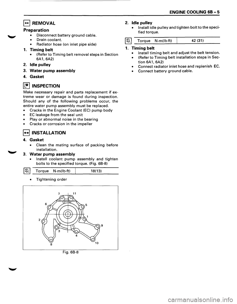
• Install coolant pump assembly and tighten
bolts to the specified torque. (Fig. 68-8)
~~~ Torque N-m(lb-ft)
•
Tightening order
Fig. 68-8
18(13)
ENGINE COOLING 68-5
2. Idle pulley
• Install idle pulley and tighten bolt to the speci
fied
torque.
~~~ Torque N-m(lb·ft) 42 (31)
1. Timing belt
• Install timing belt and adjust the belt tension.
• (Refer to Timing belt installation steps in Sec
tion 6A1, 6A2)
• Connect radiator inlet hose and replenish EC.
• Connect battery ground cable.
Page 636 of 1928
'.,~-' r.
68-8 ENGINE COOLING
2. Radiator hose
• Disconnect inlet hose and outlet hose from the
engine.
3. Fan guide, lower
• Remove clips on both sides and the bottom
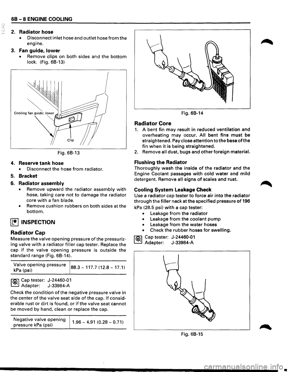
lock. (Fig. 68-13)
~ Cooling fan guide; lower
~
Clip
Fig. 68-13
4. Reserve tank hose
• Disconnect the hose from radiator.
5. Bracket
6. Radiator assembly
• Remove upward the radiator assembly with
hose, taking care not to damage the radiator
core
with a fan blade.
• Remove cushion rubbers on both sides at the
bottom.
~ INSPECTION
Radiator Cap
Measure the valve opening pressure of the pressuriz
ing valve with a radiator filler cap tester. Replace the
cap
if the valve opening pressure is outside the
standard range (Fig. 68-14).
~;!v(~~i~ening pressure 88.3-117.7 (12.8-17.1)
l'i':'il Cap tester: J-24460-01
~ Adapter: J-33984-A
Check the
condition of the negative pressure valve in
the center
of the valve seat side of the cap. If consid
erable rust
or dirt is found, or if the valve seat cannot
be
moved by hand, clean or replace the cap.
Negative
valve opening
pressure kPa (psi) 1.96-4.91 (0.28-0.71)
Fig. 68-14
Radiator Core
1. A bent fin may result in reduced ventilation and
overheating
may occur. All bent fins must be
straightened. Pay
close attention to the base of the
fin when it is being straightened.
2. Remove all dust, bugs and other foreign material.
Flushing the Radiator
Thoroughly wash the inside of the radiator and the
Engine
Coolant passages with cold water and mild
detergent. Remove all signs of scales and rust.
Cooling System Leakage Check
Use a radiator cap tester to force air into the radiator
through the filler neck at the specified pressure of 196
kPa (28.5 psi) with a cap tester:
• Leakage from the radiator
• Leakage from the coolant pump
• Leakage from the water hoses
• Check the rubber hoses for swelling.
rt:\1 Cap tester: J-24460-01
~ Adapter: J-33984-A
Fig. 68-15
•
Page 646 of 1928
![ISUZU TROOPER 1995 User Guide 6C - 4 ENGINE FUEL
I1!]1NSPECTION
After installation, start engine and check for fuel leak
age.
IN-TANK FUEL FILTER
The filter is located on the lower end of fuel pickup
tube in the fuel tank](/img/61/57183/w960_57183-645.png "ISUZU TROOPER 1995 User Guide 6C - 4 ENGINE FUEL
I1!]1NSPECTION
After installation, start engine and check for fuel leak
age.
IN-TANK FUEL FILTER
The filter is located on the lower end of fuel pickup
tube in the fuel tank")
6C - 4 ENGINE FUEL
I1!]1NSPECTION
After installation, start engine and check for fuel leak
age.
IN-TANK FUEL FILTER
The filter is located on the lower end of fuel pickup
tube in the fuel tank. It prevents dirt from entering the
fuel pipe and also stops water unless the filter is
completely submerged in the water. It is a self-cleaning
type, not requiring scheduled maintenance. Excess
water and sediment in the tank restricts fuel supply to
the engine, resulting in engine stop. In such a case, the
tank
must be cleaned throughly.
FUEL PUMP FLOW TEST
If reduction of fuel supply is suspected, perform
checking as follows.
Preparation:
• Make sure that there is fuel in the tank.
• With the engine running, check the fuel feed
pipe and hose
from fuel tank to injector for
evidence of leakage.
Retighten, if pipe or hose connection is loose.
Also,
check pipes and hoses for squashing or
clogging.
1. Receive the hose from fuel feed pipe with a clean
container, and check for fuel pump flow rate.
2. Connect the pump relay terminals with a jumper
wire as shown and start the fuel pump to measure
delivery. (Fig. 6C-4)
W CAUTION:
Never generate sparks when connecting a jumper
wire.
Fig. 6C-4
Delivery Delivery
15 seconds 0.38
liters minimum
If the measure value is out of standard, conduct the
pressure test.
Pressure test
For the pressure test to the fuel system, see Section 6E
"Fuel Control System".
II
Page 780 of 1928
6E2-84 DRIVEABILITY AND EMISSIONS
DIAGNOSTIC TROUBLE CODE (DTC) 44
HEATED OXYGEN SENSOR (H02S) CIRCUIT
(LEAN HEATED OXYGEN SENSOR (H02S) SIGNAL INDICATED)
Circuit Description:
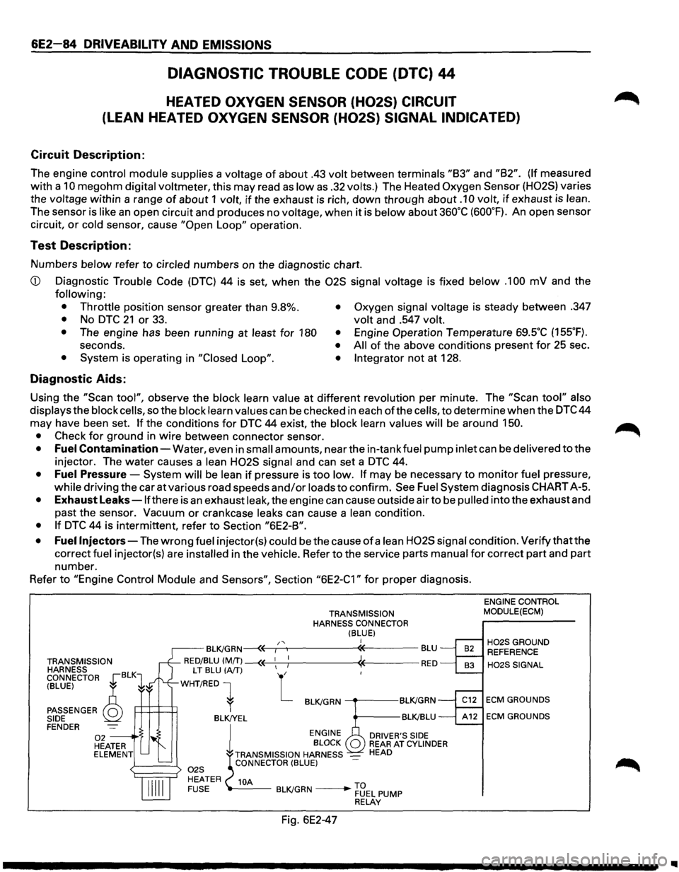
The engine control module supplies a voltage of about .43 volt between terminals "83" and "82". (If measured
with a
10 megohm digital voltmeter, this may read as low as .32 volts.) The Heated Oxygen Sensor (H02S) varies
the
voltage within a range of about 1 volt, if the exhaust is rich, down through about .1 0 volt, if exhaust is lean.
The sensor is like an open circuit and produces no voltage, when it is below about 360°C (600°F). An open sensor
circuit,
or cold sensor, cause "Open Loop" operation.
Test Description:
Numbers below refer to circled numbers on the diagnostic chart.
CD Diagnostic Trouble Code (DTC) 44 is set, when the 02S signal voltage is fixed below .1 00 mV and the
following:
• Throttle
position sensor greater than 9.8%.
• No DTC 21 or 33. • Oxygen signal voltage is steady between .347
volt and .547 volt.
•
The engine has been running at least for 180 •
seconds. • • System is operating in "Closed Loop". •
Engine Operation Temperature 69SC (155°F).
All of the above conditions present for 25 sec .
Integrator not at 128 .
Diagnostic Aids:
Using the "Scan tool", observe the block learn value at different revolution per minute. The "Scan tool" also
displays
the block cells, so the block learn values can be checked in each ofthe cells, to determine when the DTC 44
may have been set.
If the conditions for DTC 44 exist, the block learn values will be around 150.
•
Check for ground in wire between connector sensor.
• Fuel Contamination-Water, even in small amounts, near the in-tank fuel pump inlet can be delivered to the
injector. The water causes a
lean H02S signal and can set a DTC 44.
• Fuel Pressure-System will be lean if pressure is too low. If may be necessary to monitor fuel pressure,
while driving the car at various road speeds and/or loads to confirm. See Fuel System diagnosis CHART A-5.
• Exhaust Leaks -lfthere is an exhaust leak, the engine can cause outside air to be pulled into the exhaust and
past the sensor.
Vacuum or crankcase leaks can cause a lean condition.
• If DTC 44 is intermittent, refer to Section "6E2-8".
• Fuel
Injectors-The wrong fuel injector(s) could be the cause of a lean H02S signal condition. Verify that the
correct
fuel injector(s) are installed in the vehicle. Refer to the service parts manual for correct part and part
number.
Refer
to "Engine Control Module and Sensors", Section "6E2-C1" for proper diagnosis.
TRANSMISSION
HARNESS
CONNECTOR
~BLK1
TRANSMISSION
HARNESS CONNECTOR
(BLUE) I /' BL~GRN~r-~----------~-------BLU
RED/BLU (MfT) --(( 1
1 ; « RED
(BLUE) ~
PASSENGER Q SIDE
LT BLU (A/T) L
WHT/RED 1
P:::l=t=t1 l BL~GRN ----.-----BL~GRN
BLK!YEL BL~BLU FENDER 02 --·S HEATER ELEMENT l
ENGINE
DRIVER'S SIDE BLOCK REAR AT CYLINDER
TRANSMISSION HARNESS _ HEAD CONNECTOR (BLUE)
10A -----BL~GRN ____ .,.... ~3EL PUMP RELAY
Fig. 6E2-47
ENGINE CONTROL
MODULE(ECM)
H02SGROUND REFERENCE
H02SSIGNAL
ECM GROUNDS
ECM GROUNDS
..
Page 883 of 1928

AUTOMATIC TRANSMISSION (4L30-E) 7 A-11
FUNCTIONS OF INPUT /OUTPUT COMPONENTS
Components Function
Speed sensor
Senses rotation
of output shaft and feeds the data to Transmission
(fixed
to transmission (T/M)) Control Module (TCM)
Throttle Senses the extent of throttle valve opening and the speed of the throttle
position sensor (TPS) valve lever motion to open the valve and feeds the data to TCM (fed to
(fixed to engine)
Engine Control Module (ECM) also)
I
Brake Switch (SW) Senses whether the driver has pressed the brake pedal or not and feeds
N (fixed
to brake pedal) the
information to TCM
p Kick-down SW (fixed to Senses whether the driver has pushed the accelerator pedal fully or not
u accelerator pedal) and feeds the information to TCM
T Mode
SW (fixed to T/M) Senses the select lever position and feeds the information to TCM
s Power drive SW Senses whether the driver has selected the power mode and feeds the
I (fixed to front console) information to TCM
G T/M
oil temp. sensor
Senses the T/M oil temperature and feeds the data to TCM
N Engine
coolant Senses the engine cooling water temperature and feeds the data to TCM
A temperature
SW (feeds the signal from ECM)
L
Engine speed
signal Feeds the signals monitoring engine speed to TCM from Ignition Control
Module
(fed to ECM also)
Air conditioning Senses whether the air conditioner has been switched on or not and
information feeds the information
to TCM
On-board diagnostic
input By monitoring the Ground (GND), the location of failure is shown on the
T/M
monitor lamp ("CHECK TRANS") by flashing the diagnostic trouble
code
Winter switch
Senses whether the driver has selected the winter mode, and feeds the
(fixed
to front console) information to TCM
Cruise
controller Downshift takes place when Overdrive OFF signal is received from auto
(Overdrive
OFF signal) cruise control unit
Shift
solenoid Selects shift point and gear position suited to the vehicle running con-s 1-2/3-4, 2-3
dition on the basis of TCM output 0 Band apply solenoid
Controls oil flow suited to the vehicle running condition on the basis of L
E TCM output
0 N
Torque
Converter Controls clutch engagement/disengagement suited to the vehicle
u 0 Clutch solenoid running condition on the basis of TCM output
T I Force motor Adjusts the oil pump delivery pressure to line pressure suited to the p D
(Pressure regulator vehicle running condition on the basis of TCM output u valve) T
Power drive mode lamp
Informs the driver whether the vehicle is in power mode or not
s Winter drive mode lamp Informs the driver whether the vehicle is in winter mode or not
I T/M monitor lamp Informs the driver of failure in the system. It also displays the self diagnosis
G
("CHECK TRANS") code.
N Data Link Connector
(DLC) When connected with TECH 1 or tester, can communicate the data for A
L function
check, etc. (fed to ECM also). When TECH 1 is not connected, can
communicate the
signal for torque management with ECM.
Self-diagnosis connector
When short-circuited with the bipolar connector, the T/M monitor lamp
displays
a failure by code.
ATF warning
lamp Lights when ATF oil temperature rises.
ABS signal When the select lever is at "Reverse" or "L" range, sends a signal to the
ABS controller as one of the ABS control conditions.