wheel bolt torque ISUZU TROOPER 1995 User Guide
[x] Cancel search | Manufacturer: ISUZU, Model Year: 1995, Model line: TROOPER, Model: ISUZU TROOPER 1995Pages: 1928
Page 216 of 1928
3F4-6 SUPPLEMENTAL RESTRAINT SYSTEM ISRSI STEERING WHEEL & COLUMN
2. Horn lead
3. Steering wheel fixing nut
4. Steering wheel
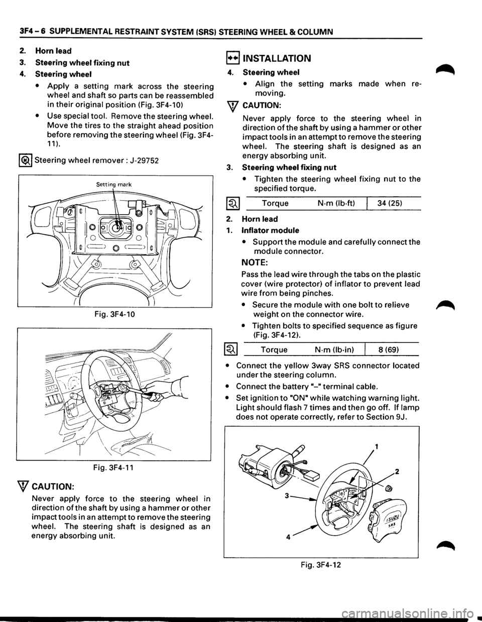
• Apply a setting mark across the steering
wheel and shaft so parts can be reassembled
in
their original position (Fig. 3F4-10)
•
Use special tool. Remove the steering wheel.
Move the tires to the straight ahead position
before removing
the steering wheel (Fig. 3F4-
11 ).
1®.1 Steering wheel remover: J-29752
Setting mark
Fig. 3F4-10
Fig. 3F4-11
"fCAUTION:
Never apply force to the steering wheel in
direction
ofthe shaft by using a hammer or other
impacttools in an attemptto remove the steering
wheel. The steering shaft is designed as an
energy absorbing unit.
B INSTALLATION
4. Steering wheel
• Align the setting marks made when re
moving.
"f CAUTION:
3.
~
2.
1.
~
Never apply force to the steering wheel in
direction
of the shaft by using a hammer or other
impacttools in an attemptto remove the steering
wheel. The steering shaft is designed as an
energy absorbing unit.
Steering wheel fixing nut
• Tighten the steering wheel fixing nut to the
specified torque.
Torque
N-m (lb·ft) 34 (25)
Horn
lead
Inflator module
• Support the module and carefully connect the
module connector.
NOTE:
Pass the lead wire through the tabs on the plastic
cover (wire protector) of inflator to prevent lead
wire from being pinches.
• Secure the module with one bolt to relieve
weight on the connector wire.
• Tighten bolts to specified sequence as figure
(Fig. 3F4-12).
Torque
N·m (lb-in) 8 (69)
• Connect the yellow 3way SRS connector located
under the steering column.
• Connect the battery"-" terminal cable.
• Set ignition to "ON• while watching warning light.
Light
should flash 7 times and then go off. If lamp
does not operate correctly, refer to Section 9J.
Fig. 3F4-12
~
•
Page 219 of 1928
SUPPLEMENTAL RESTRAINT SYSTEM (SRS) STEERING WHEEL & COLUMN 3F4-9
B INSTALLATION
6. Combination switch and SRS coil assembly
•
After installation of combination switch as
sembly, connect the combination switch
wiring harness connector and the SRS 3way
connector located under the steering column.
•
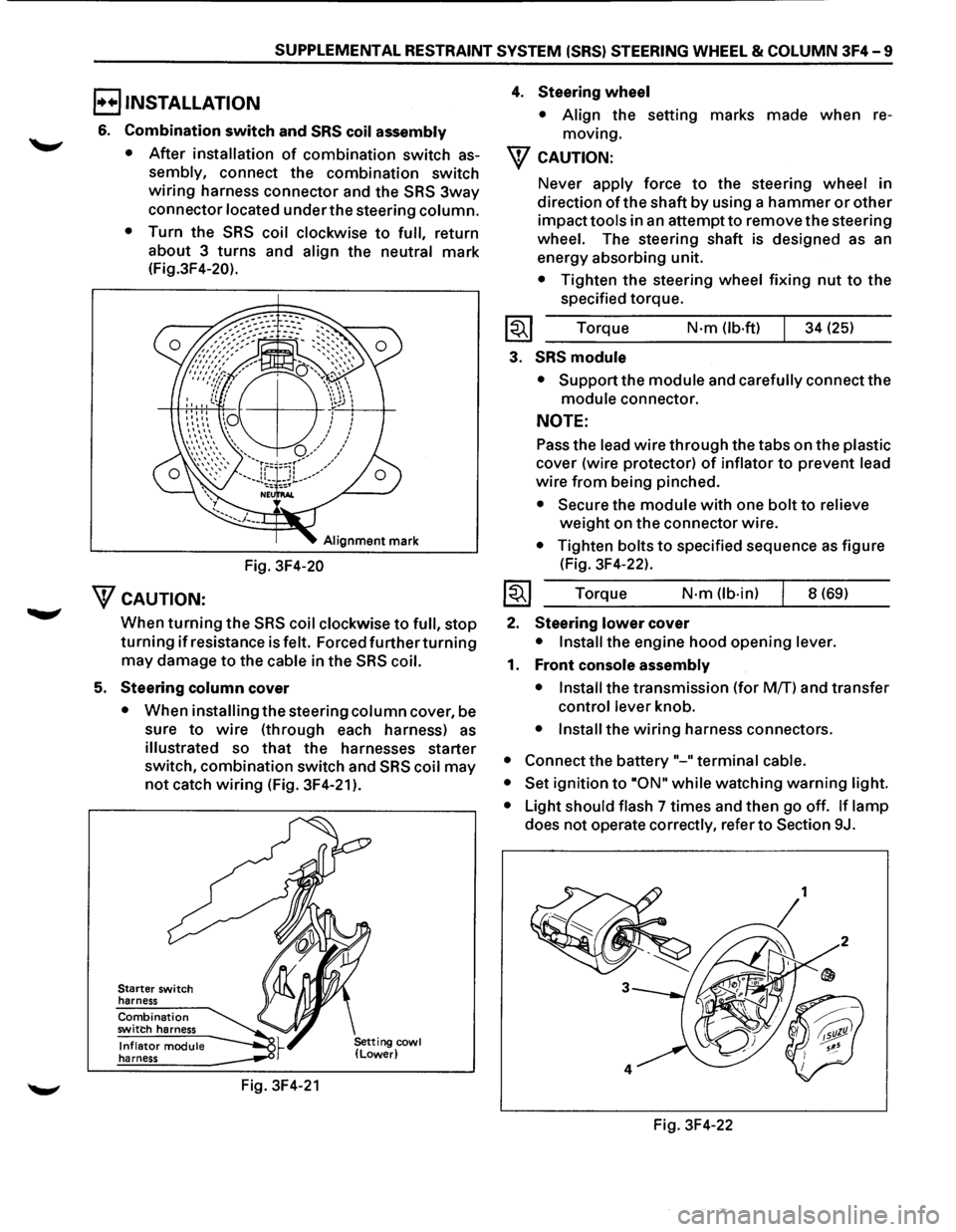
Turn the SRS coil clockwise to full, return
about 3
turns and align the neutral mark
(Fig.3F4-20).
Alignment mark
Fig. 3F4-20
WcAUTION:
When turning the SRS coil clockwise to full, stop
turning if resistance is felt. Forced further turning
may damage to the cable in the SRS coil.
5. Steering column cover
• When installing the steering column cover, be
sure
to wire (through each harness) as
illustrated so that the harnesses starter
switch,
combination switch and SRS coil may
not catch wiring (Fig. 3F4-21 ).
Starter switch
harness
Combination switch harness
Inflator module harness
Fig. 3F4-21
4. Steering wheel
• Align the setting marks made when re
moving.
W CAUTION:
Never apply force to the steering wheel in
direction
of the shaft by using a hammer or other
impact tools in an attempt to remove the steering
wheel. The steering shaft is designed as an
energy absorbing unit.
• Tighten the steering wheel fixing nut to the
specified torque.
Torque
N·m (lb-ft) 34 (25)
3. SRS module
• Support the module and carefully connect the
module connector.
NOTE:
Pass the lead wire through the tabs on the plastic
cover (wire protector) of inflator to prevent lead
wire from being pinched.
• Secure the module with one bolt to relieve
weight on the connector wire.
• Tighten bolts to specified sequence as figure
(Fig. 3F4-22).
Torque
N·m (lb·in) 8 (69)
2. Steering lower cover
• Install the engine hood opening lever.
1. Front console assembly
• Install
the transmission (for MfT) and transfer
control lever knob.
• Install the wiring harness connectors.
• Connect the battery "-"terminal cable.
• Set
ignition to ·oN" while watching warning light.
•
Light should flash 7 times and then go off. If lamp
does not operate correctly, refer to Section 9J.
Fig. 3F4-22
Page 222 of 1928
3F4 -12 SUPPLEMENTAL RESTRAINT SYSTEM (SRS) STEERING WHEEL & COLUMN
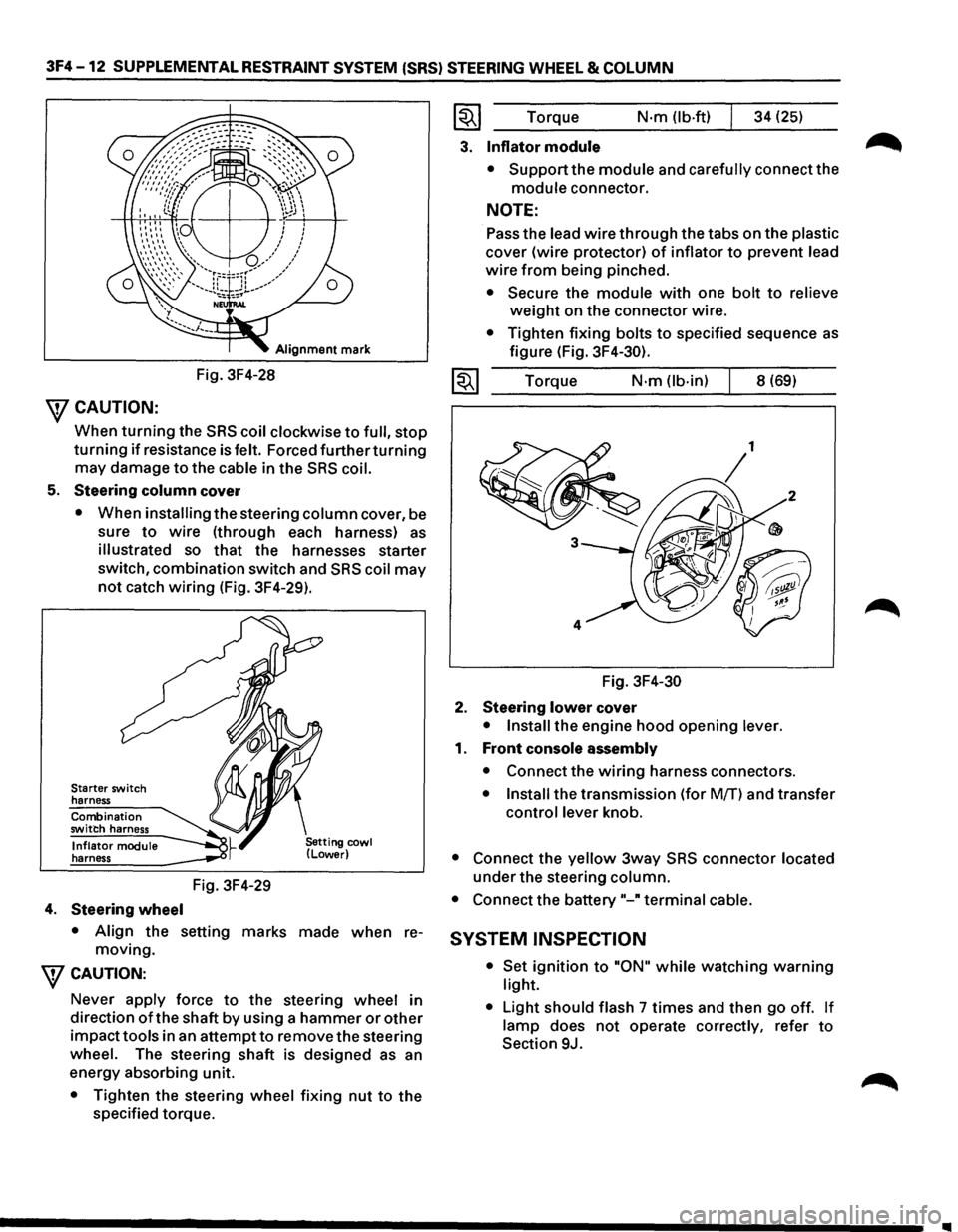
Alignment mark
Fig. 3F4-28
\fCAUTION:
When turning the SRS coil clockwise to full, stop
turning if resistance is felt. Forced further turning
may damage to the cable in the SRS coil.
5. Steering column cover
• When installing the steering column cover, be
sure
to wire (through each harness) as
illustrated so that the harnesses starter
switch,
combination switch and SRS coil may
not catch wiring (Fig. 3F4-29).
Starter switch
harness
Combination
switch harness
Inflator module
harness
4. Steering wheel
Fig. 3F4-29
• Align the setting marks made when re
moving.
\fCAUTION:
Never apply force to the steering wheel in
direction
of the shaft by using a hammer or other
impacttools in an attemptto remove the steering
wheel. The steering shaft is designed as an
energy absorbing unit.
• Tighten the steering wheel fixing nut to the
specified torque.
~~~ Torque N·m (lb-ft) 34 (25)
3. Inflator module
• Support the module and carefully connect the
module connector.
NOTE:
Pass the lead wire through the tabs on the plastic
cover (wire protector) of inflator to prevent lead
wire from being pinched.
• Secure the module with one bolt to relieve
weight on the connector wire.
• Tighten fixing bolts to specified sequence as
figure (Fig. 3F4-30).
1~1 Torque N·m (lb-in) 8 (69)
Fig.
3F4-30
2. Steering lower cover
• Install the engine hood opening lever.
1. Front console assembly
• Connect the wiring harness connectors.
• Install the transmission (for Mff) and transfer
control lever knob.
• Connect the yellow 3way SRS connector located
under the steering column.
• Connect the battery"-" terminal cable.
SYSTEM INSPECTION
• Set ignition to "ON" while watching warning
light.
•
Light should flash 7 times and then go off. If
lamp does not operate correctly, refer to
Section 9J.
Page 225 of 1928
SUPPLEMENTAL RESTRAINT SYSTEM (SRS) STEERING WHEEL & COLUMN 3F4-15
Fig. 3F4-35
6. Steering column cover
7. Combination switch and SRS coil assembly
•
Disconnect the wiring harness connectors
located under the steering column.
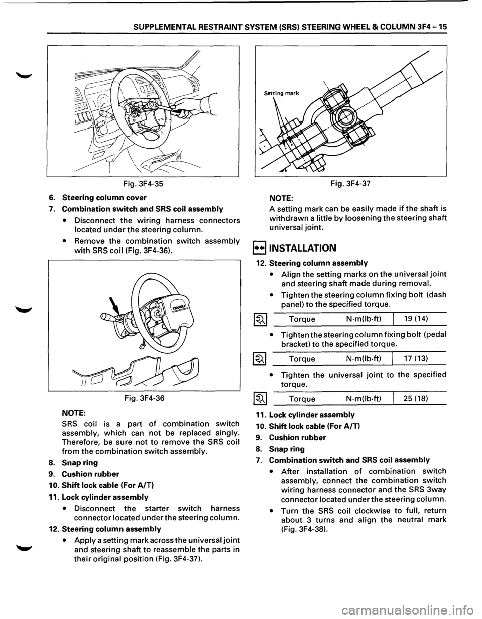
• Remove the combination switch assembly
with SRS coil (Fig. 3F4-36).
Fig. 3F4-36
NOTE:
SRS coil is a part of combination switch
assembly, which can not be replaced singly.
Therefore, be sure not to remove the SRS coil
from the combination switch assembly.
8. Snap ring
9. Cushion rubber
10. Shift lock cable (For A/T)
11. Lock
cylinder assembly
• Disconnect the starter switch harness
connector located under the steering column.
12. Steering column assembly
•
Apply a setting mark across the universal joint
and steering shaft to reassemble the parts in
their original position (Fig. 3F4-37). Fig.
3F4-37
NOTE:
A setting mark can be easily made if the shaft is
withdrawn a little by loosening the steering shaft
universal joint.
B INSTALLATION
12. Steering column assembly
• Align the setting marks on the universal joint
and steering shaft made during removal.
•
Tighten the steering column fixing bolt (dash
panel) to the specified torque.
Torque
N-mOb·ft) 19 (14)
• Tighten the steering column fixing bolt (pedal
bracket) to the specified torque.
Torque N·m(lb·ft) 17 (13)
• Tighten the universal joint to the specified
torque.
Torque
N-m(lb·ft)
11. Lock cylinder assembly
10.
Shift lock cable (For A/T)
9. Cushion rubber
8. Snap ring
25 (18)
7. Combination switch and SRS coil assembly
• After installation of combination switch
assembly, connect the combination switch
wiring harness connector and the SRS 3way
connector located under the steering column.
•
Turn the SRS coil clockwise to full, return
about 3 turns and align the neutral mark
(Fig. 3F4-38).
Page 226 of 1928
3F4-16 SUPPLEMENTAL RESTRAINT SYSTEM (SRS) STEERING WHEEL & COLUMN
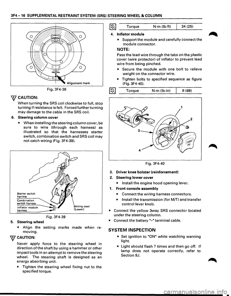
Alignment mark
Fig. 3F4-38
\fCAUTION:
When turning the SRS coil clockwise to full, stop
turning if resistance is felt. Forced furtherturning
may damage to the cable in the SRS coil.
6. Steering column cover
• When installing the steering column cover, be
sure
to wire (through each harness) as
illustrated so that the harnesses starter
switch,
combination switch and SRS coil may
not catch wiring (Fig. 3F4-39).
Starter switch
harness
Combination switch harness
Inflator module harness
5. Steering wheel
Fig. 3F4-39
• Align the setting marks made when re
moving.
WCAUTION:
Never apply force to the steering wheel in
direction
ofthe shaft by using a hammer or other
impacttools in an attempt to remove the steering
wheel. The steering
shaft is designed as an
energy absorbing unit.
• Tighten the steering wheel fixing nut to the
specified torque. Torque
N·m (lb·ftl 34
(25)
4. Inflator module
• Support the module and carefully connect the
module connector.
NOTE:
Pass the lead wire through the tabs on the plastic
cover (wire protector) of inflator to prevent lead
wire from being pinched.
• Secure the module with one bolt to relieve
weight on the connector wire.
• Tighten bolts to specified sequence as figure
(Fig. 3F4-40).
Torque
N·m (lb-in) 8 (69)
Fig. 3F4-40
3. Driver knee bolster (reinforcement)
2. Steering lower cover
• Install the engine hood opening lever.
1. Front console assembly
• Connect the wiring harness connectors.
• Install the transmission (for M/T) and transfer
control lever knob.
• Connect the yellow 3way SRS connector located
under the steering column.
• Connect the battery "-"terminal cable.
SYSTEM INSPECTION
• Set ignition to "ON" while watching warning
light.
• Light should flash 7 times and then go off. If
lamp does not operate correctly, refer to
Section 9J.
•
Page 248 of 1928
48-6 REAR AXLE
1••1 INSTALLATION
17. Differential assembly
• Refer to "DIFFERENTIAL ASSEMBLY" in this
section.
16.
Axle shaft assembly
• Tighten the bearing holder mounting nut to the
specified torque.
~~~ Torque N·m (lb·ft) 74 (54)
• Be sure not to damage the oil seal by the spline
of the shaft.
15. Brake
pipe
14. Antilock brake system (ABS) speed sensor and
harness
• Refer to Section 5A4 "4-WHEEL ANTI-LOCK
BRAKE SYSTEM (ABS)".
13. Brake disc
12. Brake
caliper
• Refer to Section 5A2 "DISC BRAKES".
11.
Axle housing assembly
10. Coil spring and insulator
9. Bolt and nut
• For the procedures in Items 9-5, refer to Section
3D "REAR SUSPENSION".
8. Bolt and nut
7. Nut
6. Nut
5. Nut
4. Brake tube flare nut
• Refer to Section 5A2 "DISC BRAKES".
3a. Rear Wheel Antilock (RWAL) speed sensor,
bracket and harness connector
• Tighten the speed sensor bolt to the specified
torque.
1~1 Torque N-m (lb·ft) j 24 (18)
3. ABS connector and bracket
2. Breather hose
1. Parking brake cable
• Refer to Section 5C "PARKING BRAKES".
Page 251 of 1928
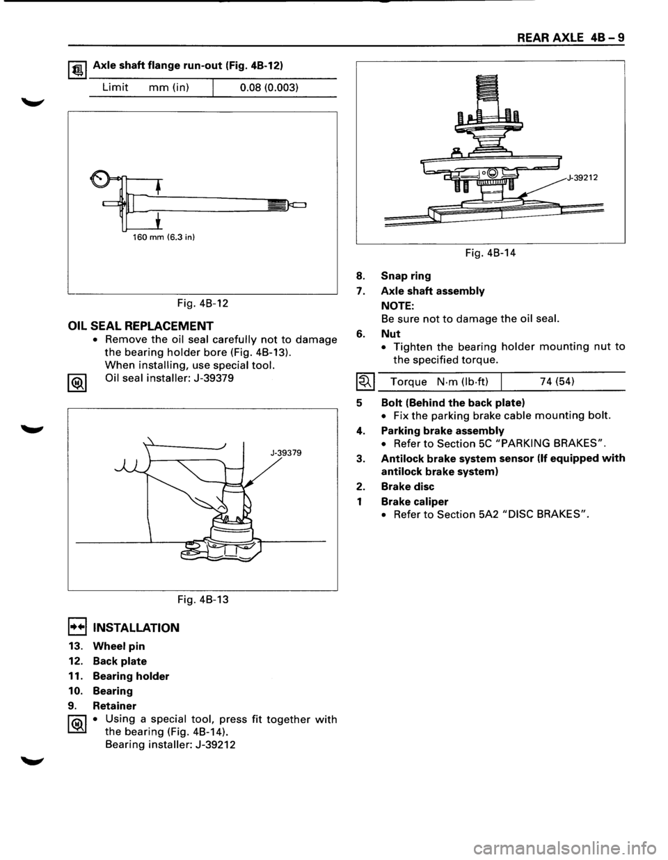
1 t!!.l Axle shaft flange run-out (Fig. 4B-12)
Limit mm (in) I 0.08 (0.003)
160 mm (6.3 in)
Fig. 4B-12
OIL SEAL REPLACEMENT
• Remove the oil seal carefully not to damage
the bearing holder bore (Fig. 4B-13).
When installing, use special tool.
1®1 Oil seal installer: J-39379
Fig. 4B-13
I••IINSTALLATION
13. Wheel pin
12. Back plate
11. Bearing holder
10. Bearing
9. Retainer
J-39379
1 ®I • Using a special tool, press fit together with
the bearing (Fig. 4B-14).
Bearing
installer: J-39212
8.
7.
6.
Fig. 4B-14
Snap ring
Axle shaft assembly
NOTE:
REAR AXLE 48-9
39212
Be sure not to damage the oil seal.
Nut
• Tighten the bearing holder mounting nut to
the specified torque.
I~I ___ T_o_rq_u_e __ N_·_m_(_lb_·f_t)~l _____ 7_4_(~5~4) ____ ___
5
4.
3.
2.
1
Bolt (Behind the back plate)
• Fix the parking brake cable mounting bolt.
Parking brake assembly
• Refer to Section 5C "PARKING BRAKES".
Antilock brake system sensor (If equipped with
antilock brake system)
Brake disc
Brake caliper
• Refer to Section 5A2 "DISC BRAKES".
Page 268 of 1928
48-26 REAR AXLE
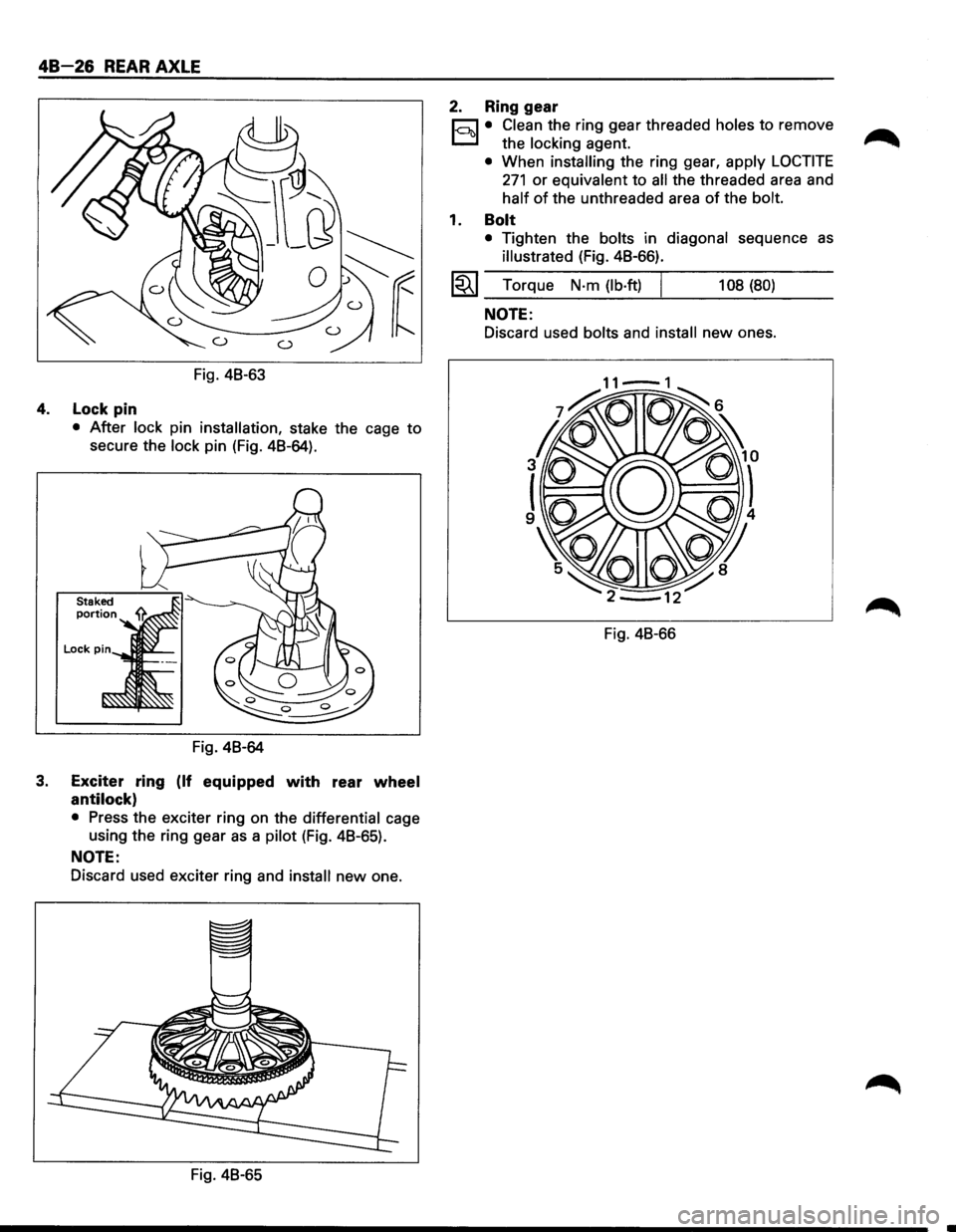
Fig. 48-63
4. Lock pin
• After lock pin installation, stake the cage to
secure the lock pin (Fig. 48-64).
Fig. 48-64
3. Exciter ring (If equipped with rear wheel
antilock)
• Press the exciter ring on the differential cage
using the ring gear
as a pilot (Fig. 48-65).
NOTE:
Discard used exciter ring and install new one.
Fig. 48-65
2. Ring gear
r;:::;J • Clean the ring gear threaded holes to remove
D the locking agent.
• When installing the ring gear, apply LOCTITE
271 or equivalent to all the threaded area and
half of the unthreaded area of the bolt.
1. Bolt
• Tighten the bolts in diagonal sequence as
illustrated (Fig. 48-66).
l~l Torque N·m (lb·ft) I 108 (80)
NOTE:
Discard used bolts and install new ones.
Fig. 48-66
Page 309 of 1928
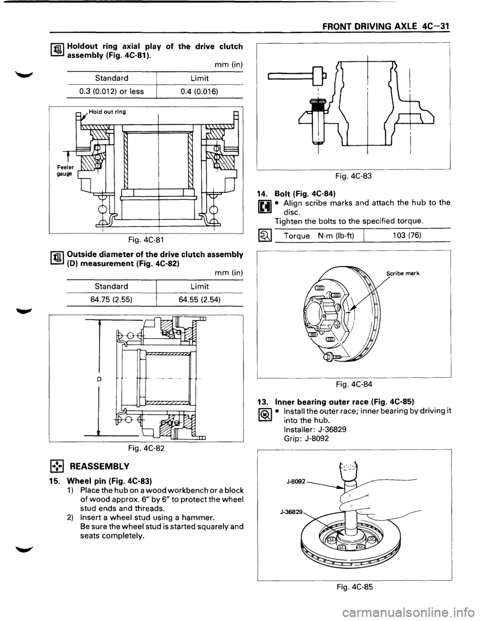
r.r.il Holdout ring axial play of the drive clutch
1..!!:.1 assembly (Fig. 4C-81 ).
mm (in)
Standard Limit
----~----------------0.3 (0.012) or less 0.4 (0.016)
Fig. 4C-81
r.r.il Outside diameter of the drive clutch assembly
1..!!:.1 (D) measurement (Fig. 4C-82)
Standard
64.75 (2.55)
Fig. 4C-82
l•! .. l REASSEMBLY
15. Wheel pin (Fig. 4C-83)
mm (in)
Limit
64.55 (2.54)
1) Place the hub on a wood workbench or a block
of wood approx. 6" by 6" to protect the wheel
stud ends and threads.
2) Insert a wheel stud using a hammer.
Be sure the wheel stud is started squarely and
seats completely.
FRONT DRIVING AXLE 4C-31
...____[)
Fig. 4C-83
14.
Bolt (Fig. 4C-84)
0 • A.lign scribe marks and attach the hub to the
1!!:!1 diSC.
Tighten the bolts to the specified torque.
~~~ Torque N·m (lb·ft) I 103 (76)
Scribe mark
Fig. 4C-84
13.
Inner bearing outer race (Fig. 4C-85)
1'?.:\1 • Install the outer race; inner bearing by driving it
l..::5::il into the hub.
Installer: J-36829
Grip:
J-8092
Fig. 4C-85
Page 327 of 1928
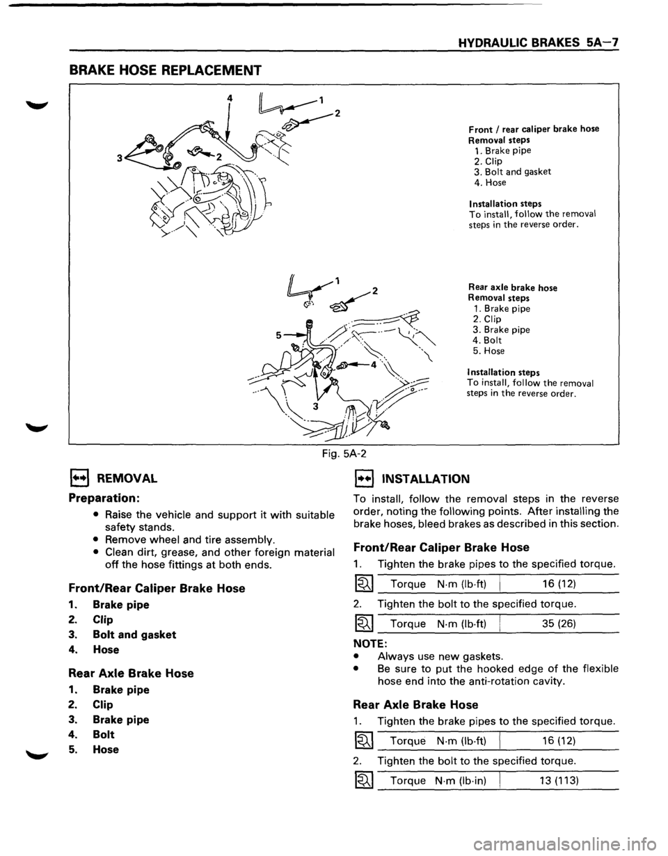
BRAKE HOSE REPLACEMENT
HYDRAULIC BRAKES 5A-7
Front I rear caliper brake hose
Removal steps 1. Brake pipe
2. Clip 3. Bolt and gasket
4. Hose
Installation steps To install, follow the removal steps in the reverse order.
Rear axle brake hose Removal steps
1. Brake pipe
2. Clip 3. Brake pipe
4. Bolt
5. Hose
Installation steps To install, follow the removal steps in the reverse order.
Fig. 5A-2
l••l REMOVAL
Preparation:
• Raise the vehicle and support it with suitable
safety stands.
• Remove wheel and tire assembly.
• Clean dirt, grease, and other foreign material
off the hose fittings at both ends.
Front/Rear Caliper Brake Hose
1. Brake pipe
2. Clip
3. Bolt and gasket
4. Hose
Rear Axle Brake Hose
1. Brake pipe
2. Clip
3. Brake pipe
4. Bolt
5. Hose
1••1 INSTALLATION
To install, follow the removal steps in the reverse
order, noting the following points. After installing the
brake
hoses, bleed brakes as described in this section.
Front/Rear Caliper Brake Hose
1. Tighten the brake pipes to the specified torque.
1«1 Torque N-m (lb·ft) 16 (12)
2. Tighten the bolt to the specified torque.
1«1 Torque N-m (lb-ft) 35 (26)
NOTE:
• Always use new gaskets.
• Be sure to put the hooked edge of the flexible
hose end into the anti-rotation cavity.
Rear Axle Brake Hose
1. Tighten the brake pipes to the specified torque.
1«1 Torque N-m (lb-ft) 16 (12)
2. Tighten the bolt to the specified torque.
1«1 Torque N·m (lb·in) 13 (113)