wheel bolt torque ISUZU TROOPER 1995 Owner's Guide
[x] Cancel search | Manufacturer: ISUZU, Model Year: 1995, Model line: TROOPER, Model: ISUZU TROOPER 1995Pages: 1928
Page 544 of 1928
6A-28 GENERAL ENGINE MECHANICAL
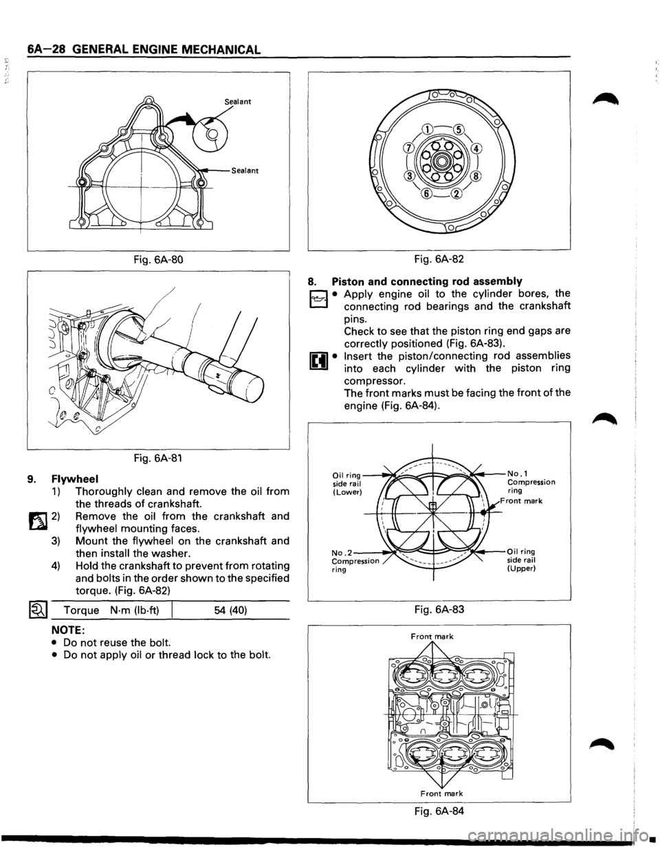
Fig. 6A-80
/
Fig. 6A-81
9. Flywheel
1) Thoroughly clean and remove the oil from
the threads
of crankshaft.
1!t1 2) Remove the oil from the crankshaft and
LQI flywheel mounting faces.
3) Mount the flywheel on the crankshaft and
then
install the washer.
4) Hold the crankshaft to prevent from rotating
and
bolts in the order shown to the specified
torque. (Fig. 6A-82)
~~~ Torque N·m (lb·ft) I ___ ___,_ ___ _ 54 (40)
NOTE:
• Do not reuse the bolt.
•
Do not apply oil or thread lock to the bolt.
Fig. 6A-82
8. Piston and connecting rod assembly
D • Apply engine oil to the cylinder bores, the
l:J connecting rod bearings and the crankshaft
pins. Check to see that the piston ring end gaps are
correctly positioned (Fig. 6A-83).
Insert the piston/connecting rod assemblies
into each cylinder with the piston ring
compressor. The
front marks must be facing the front of the
engine (Fig. 6A-84).
Oil ring ---~====-~::F::::::.===~~t---No. 1
side rail Compression (Lower) ring Front mark
No .2--~~:::::=:e!::::!-;::::!!;~~·-Oil ring
Compression side rail ring (Upper)
Fig. 6A-83
Front mark
Front mark
Fig. 6A-84
•
Page 555 of 1928
1,.!.,1 REASSEMBLY
14. Cylinder block
13. Crankshaft
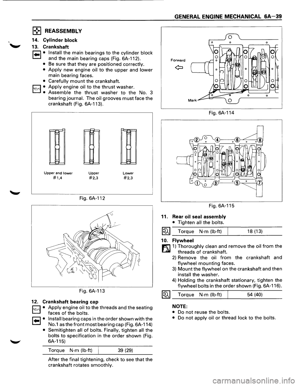
1•1• Install the main bearings to the cylinder block
and the main bearing caps (Fig. 6A-112).
• Be sure that they are positioned correctly.
•
Apply new engine oil to the upper and lower
main bearing faces.
• Carefully mount the crankshaft.
1~·1 .• Apply engine oil to the thrust washer.
Assemble the thrust washer to the No. 3
bearing
journal. The oil grooves must face the
crankshaft (Fig. 6A-113).
r--!::"
11-1
~
Upper and lower
#1,4
Upper
#2,3
Fig. 6A-112
Fig. 6A-113
12. Crankshaft bearing cap
Lower
#2,3
D • Apply engine oil to the threads and the seating
L:J faces of the bolts.
I• I• Install bearing caps in the order shown with the
No.1 as the front most bearing cap (Fig. 6A-114)
• Semitighten all of bolts. Finally, tighten all the
bolts to specification in the order shown (Fig.
6A-115)
Torque
N·m (lb·ft) 39 (29)
After the final tightening, check to see that the
crankshaft rotates
smoothly.
GENERAL ENGINE MECHANICAL &A-39
Forward
Fig. 6A-114
Fig. 6A-115
11. Rear oil seal assembly
• Tighten all the bolts.
~~~ Torque N·m (lb·ft)
1 0. Flywheel
18 (13)
r:l]1) Thoroughly clean and remove the oil from the
threads
of crankshaft.
2) Remove the oil from the crankshaft and
flywheel mounting faces.
3) Mount the flywheel on the crankshaft and then
install the washer.
4) Holding the crankshaft stationary, tighten the
flywheel bolts in the order shown (Fig. 6A-116).
~~~ Torque N·m (lb·ft) 54 (40)
NOTE:
•
Do not reuse the bolts.
•
Do not apply oil or thread lock to the bolts.
Page 609 of 1928
.., ¢'
-
Fig. 6A1-59
1••1 INSTALLATION
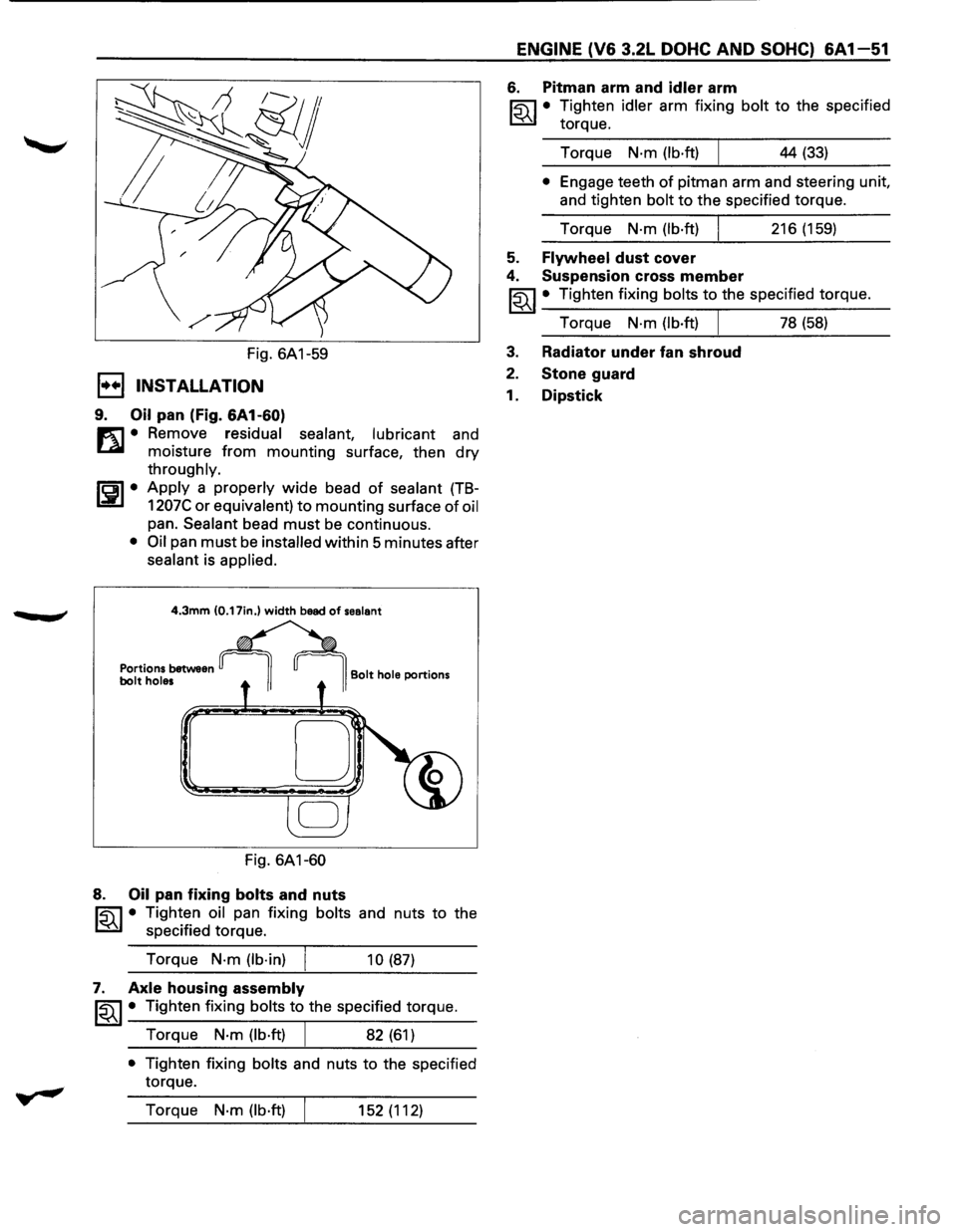
9. Oil pan (Fig. 6A1-60)
m • Remove residual sealant, lubricant and
~ moisture from mounting surface, then dry
throughly.
ISPI• Apply a properly wide bead of sealant (TB-
1207C or equivalent) to mounting surface of oil
pan. Sealant bead must be continuous.
• Oil pan must be installed within 5 minutes after
sealant is applied.
4.3mm (0.17in.) width bead of sealant
Portions between bolt holes
Fig. 6A1-60
8. Oil pan fixing bolts and nuts
Bolt hole portions
~ • Tighten oil pan fixing bolts and nuts to the
~ specified torque.
Torque
N·m (lb·in)
10 (87)
7. Axle housing assembly
~~~· Tighten fixing bolts to the specified torque.
Torque
N·m (lb·ft) 82 (61)
• Tighten fixing bolts and nuts to the specified
torque.
Torque
N·m (lb·ft) 152 (112)
ENGINE (V6 3.2L DOHC AND SOHC) 6A 1-51
6. Pitman arm and idler arm
~·
Tighten idler arm fixing bolt to the specified
torque.
Torque
N·m (lb·ft) 44 (33)
• Engage teeth of pitman arm and steering unit,
and tighten
bolt to the specified torque.
Torque
N·m (lb·ft) 216 (159)
5. Flywheel dust cover
4. Suspension cross member
~~~ • Tighten fixing bolts to the specified torque.
Torque
N·m (lb·ft) I 78 (58)
3. Radiator under fan shroud
2. Stone guard
1. Dipstick
Page 616 of 1928
,): .. • T·
6A 1-58 ENGINE (V6 3.2L DOHC AND SOHC)
EJ REMOVAL
1. Engine assembly
• See "Engine Assembly
Removal and Instal-
lation".
2. Crankshaft pulley
3. Timing belt cover
4. Timing belt
5. Oil pan
6. Oil pipe and rubber ring
7. Oil strainer and rubber ring
8. Oil pump assembly
9. Crankcase side bolts
10.
Oil gallery
11. Flywheel
12.
Rear oil seal retainers
13.
Connecting rod caps
14.
Crankshaft main bearing caps
15.
Crankshaft and main bearings
1•+1 INSTALLATION
15. Crankshaft and main bearings
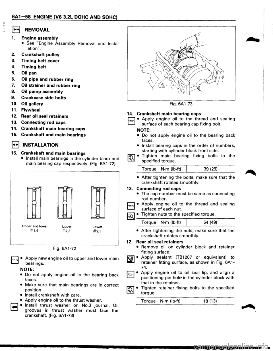
• Install main bearings in the cylinder block and
main bearing cap respectively. (Fig. 6A1-72)
r-r-'
II-
!:=
Upper and lower
#1,4
~
!::
E:
Upper
#2,3
Fig. 6A1-72
Lower
#2,3
1~1· Apply new engine oil to upper and lower main
bearings.
NOTE:
• Do not apply engine oil to the bearing back
faces.
• Make sure that main bearings are in correct
position.
• Install crankshaft with care.
• Apply engine oil to the thrust washer.
1•1• Install thrust washer on No.3 journal. Oil
grooves in thrust washer must face the
crankshaft. (Fig. 6A1-73) Fig.
6A1-73
14. Crankshaft main bearing caps
C1 • Apply engine oil to the thread and seating
L:::J surface of each bearing cap fixing bolt.
NOTE:
• Do not apply engine oil to the bearing back
faces.
• Install bearing caps in the order of numbers,
starting
with cylinder block front side.
~~~ • Tighten main bearing fixing bolts to the
specified torque.
Torque
N·m (lb·ft) I 39 (29)
• After tightening the bolts, make sure that the
crankshaft rotates
smoothly.
13. Connecting rod caps
• The cap number must be same as connecting
rod number.
1~1· Apply engine oil to the thread and sealing
surface of each nut.
~~~· Tighten nuts to the specified torque.
Torque
N·m (lb·ft) 54 (49)
• After tightening the nuts, make sure that the
crankshaft rotates
smoothly.
12. Rear oil seal retainers
• Remove oil on cylinder block and retainer
fitting surface.
~~~· Apply sealant (TB1207 or equivalent) to
retainer fitting surface, as shown in Fig. 6A 1-
74.
C1 • Apply engine oil to oil seal lip, and align a
El positioning pin hole< in the cylinder block with
that in the retainer.
~~~· Tighten retainer fixing bolts to the specified
torque.
Torque
N·m (lb·ft) 18 (13)
IIIII
Page 617 of 1928
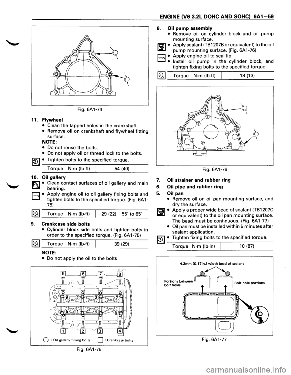
Fig. 6A1-74
11. Flywheel
• Clean the tapped holes in the crankshaft.
• Remove oil on crankshaft and flywheel fitting
surface.
NOTE:
• Do not reuse the bolts.
•
Do not apply oil or thread lock to the bolts.
~~~ • Tighten bolts to the specified torque.
Torque
N-m (lb·ft) 54 (40)
10. Oil gallery
m • Clean contact surfaces of oil gallery and main
~ bearing.
D • Apply engine oil to oil gallery fixing bolts and
L:::J tighten bolts to the specified torque. (Fig. 6A 1-
75)
~~~ Torque N·m (lb·ft) 29 (22) -55° to 65°
9. Crankcase side bolts
• Cylinder block side bolts and tighten bolts in
order
to the specified torque. (Fig. 6A 1-75)
~~~ Torque N·m (lb·ft) 39 (29)
NOTE:
• Do not apply the oil to the bolts
0 :Oil gallery fixing bolts 0: Crankcase bolts
Fig. 6A1-75
ENGINE (V6 3.2L DOHC AND SOHC) 6A1-59
8. Oil pump assembly
• Remove oil on cylinder block and oil pump
mounting surface.
ll:JI• Apply sealant (TB12078 or equivalent) to the oil
pump mounting surface. (Fig. 6A1-76)
19Y·I •. Apply engine oil to seal lip.
Install oil
pump in the cylinder block, and
tighten fixing
bolts to the specified torque.
1~1 Torque N·m (lb·ft)
Fig. 6A1-76
7. Oil strainer and rubber ring
6. Oil pipe and rubber ring
5. Oil pan
18 (13)
• Remove oil on oil pan mounting surface, and
dry the surface.
~~~· Apply a proper wide bead of sealant (TB1207C
or equivalent) to the oil pan mounting surface.
The bead
must be continuous. (Fig. 6A1-77)
• Oil pan must be installed within 5 minutes after
sealant application.
~~~· Tighten fixing bolts to the specified torque.
Torque
N·m (lb·in) 10 (87)
4.3mm (0.17in.) width bead of sealant
Portions between bolt holes I Bolt hole portions
D
Fig. 6A1-77
Page 618 of 1928
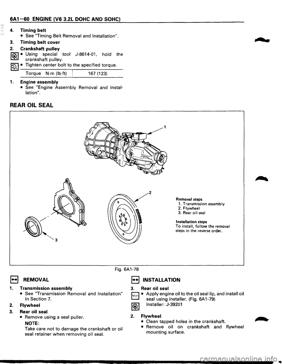
6A1-60 ENGINE (V6 3.2L DOHC AND SOHC}
4. Timing belt
• See "Timing Belt Removal and Installation".
3. Timing belt cover
2. Crankshaft pulley
~ • Using special tool J-8614-01, hold the
~ crankshaft pulley.
~~~· Tighten center bolt to the specified torque.
Torque
N·m (lb·ft) 167 (123)
1. Engine assembly
• See "Engine Assembly Removal and Instal
lation".
REAR OIL SEAL
Removal steps
1. Transmission assembly
2.
Flywheel 3. Rear oil seal
Installation steps To install, follow the removal
steps in the reverse order.
Fig. 6A1-78
E) REMOVAL
1. Transmission assembly
• See "Transmission Removal and Installation"
in Section 7.
2. Flywheel
3. Rear oil seal
•
Remove using a seal puller.
NOTE:
Take care
not to damage the crankshaft or oil
seal retainer
when removing oil seal.
1••1 INSTALLATION
3. Rear oil seal
C1 • Apply engine oil to the oil seal lip, and install oil
L:::l seal using installer. (Fig. 6A 1-79)
1®1 Installer: J-39201
2. Flywheel
• Clean tapped holes in the crankshaft.
• Remove oil on crankshaft and flywheel
mounting surface.
...
Page 648 of 1928
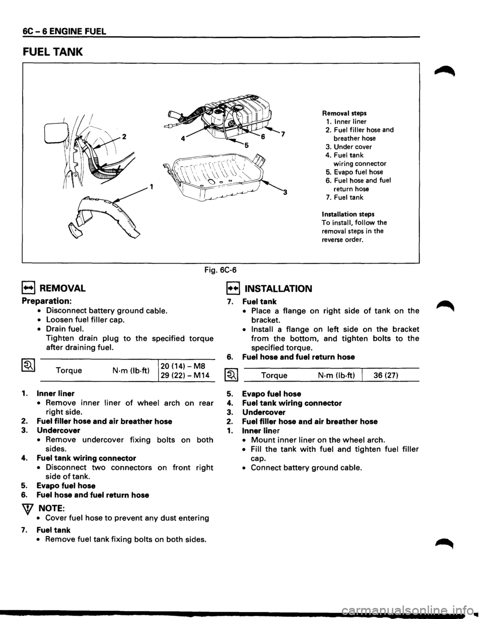
6C-6 ENGINE FUEL
FUEL TANK
7
1 3
Removal steps
1.1nnerliner
2. Fuel filler hose and
breather hose
3. Under cover
4.
Fuel tank
wiring connector
5. Evapo fuel hose
6.
Fuel hose and fuel
return hose
7. Fuel tank
Installation steps
To
install, follow the
removal steps in the
reverse order.
Fig. 6C-6
B REMOVAL
Preparation:
• Disconnect battery ground cable.
•
Loosen fuel filler cap.
• Drain fuel.
Tighten drain plug to the specified torque
after draining fuel.
Torque
1. Inner liner
N·m (lb·ft) 20 (14)-M8
29 (22)-M14
• Remove
inner liner of wheel arch on rear
right side.
2.
Fuel filler hose and air breather hose
3.
Undercover
• Remove undercover fixing bolts on both
sides.
4. Fuel tank wiring connector
• Disconnect two connectors on front right
side of tank.
5. Evapo fuel hose
6. Fuel hose and fuel return hose
W NOTE:
• Cover fuel hose to prevent any dust entering
7. Fuel tank
• Remove fuel tank fixing bolts on both sides.
I!!] INSTALLATION
7.
6.
Fuel tank
• Place a flange on right side of tank on the
bracket.
• Install a flange on left side on the bracket
from the bottom, and tighten bolts to the
specified torque.
Fuel hose and fuel return hose
Torque N·m Ob·ft) 36 (27)
5. Evapo fuel hose
4. Fuel tank wiring connector
3. Undercover
2. Fuel filler hose and air breather hose
1. Inner liner
• Mount inner liner on the wheel arch.
• Fill the tank with fuel and tighten fuel filler
cap.
• Connect battery ground cable.
Page 1032 of 1928
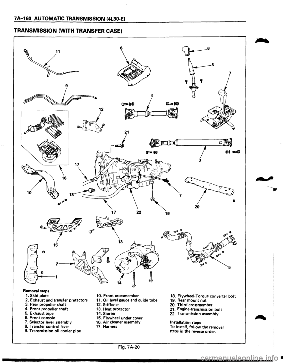
7A-160 AUTOMATIC TRANSMISSION (4L30-E)
TRANSMISSION (WITH TRANSFER CASE)
6
I
10 i
'
17 22
Removal steps
1. Skid plate 10. Front crossmember
2. Exhaust and transfer pretectors 11. Oil level gauge and guide tube
3. Rear propeller shaft
12. Stiffener
4. Front propeller shaft 13. Heat protector
5. Exhaust pipe
14. Starter
6. Front console
15. Flywheel under cover
7.
Selector lever assembly 16.
Air cleaner assembly
8. Transfer control lever
17. Harness
9. Transmission
oil cooler pipe
Fig. 7A-20
""' 19
8
7
7
20
18. Flywheel· Torque converter bolt 19. Rear mount nut 20. Third crossmember
21. Engine-transmission bolt
22. Transmission assembly
Installation steps
To
install, follow the removal
steps in the reverse order.
-A
•
Page 1034 of 1928
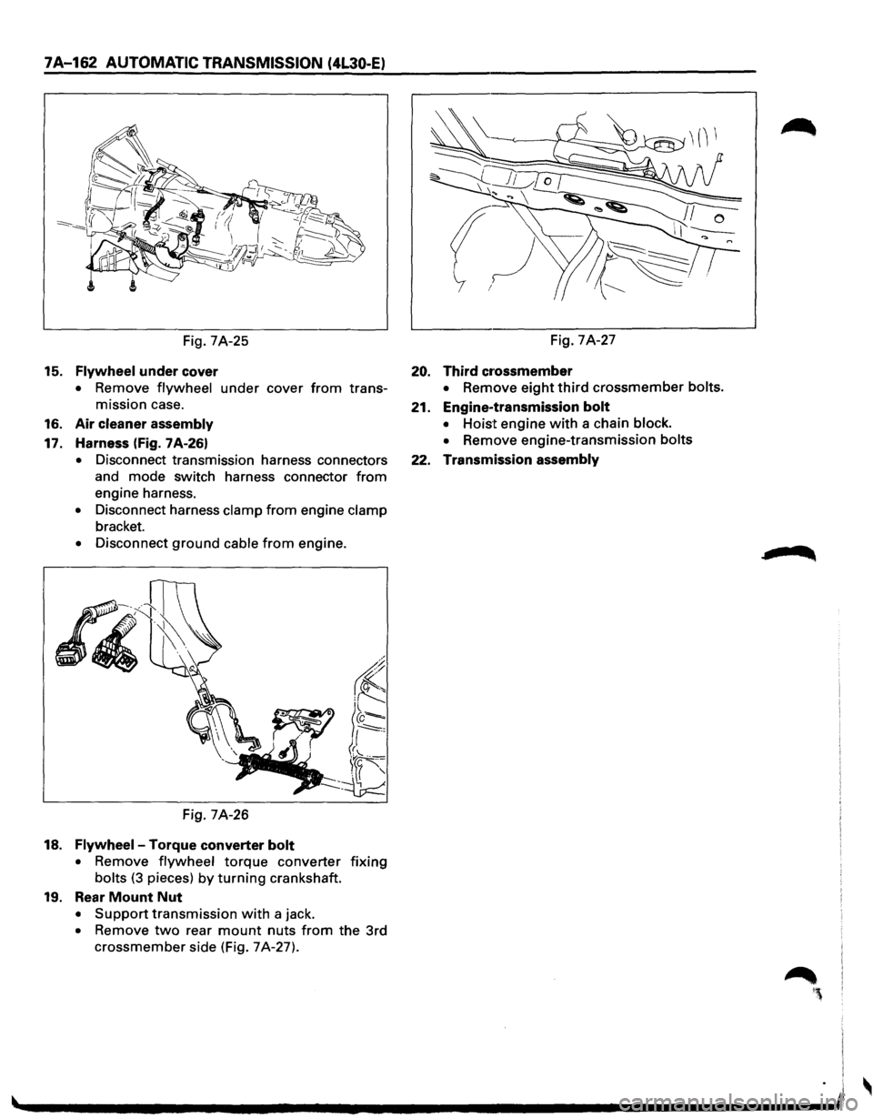
7A-162 AUTOMATIC TRANSMISSION (4L30-E)
Fig. 7A-25
15. Flywheel under cover
• Remove flywheel under cover from trans
mission case.
16. Air cleaner assembly
17. Harness (Fig. 7A-26)
• Disconnect transmission harness connectors
and mode switch harness connector
from
engine harness.
• Disconnect harness clamp from engine clamp
bracket.
• Disconnect ground cable from engine.
Fig. 7A-26
18. Flywheel-Torque converter bolt
• Remove flywheel torque converter fixing
bolts (3 pieces) by turning crankshaft.
19. Rear Mount Nut
• Support transmission with a jack.
• Remove two rear mount nuts from the 3rd
crossmember side (Fig. 7A-27). Fig.
7A-27
20. Third cr·ossmember
• Remove eight third crossmember bolts.
21. Engine-transmission bolt
• Hoist engine with a chain block.
•
Remove engine-transmission bolts
22. Transmission assembly
Page 1036 of 1928
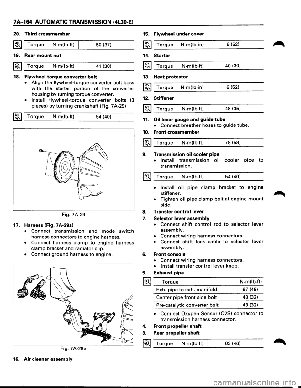
7A-164 AUTOMATIC TRANSMISSION (4L30-E)
20. Third crossmember
~~~ Torque N·m(lb.ft) 50 (37)
19. Rear mount nut
~~~ Torque N·mOb·ft) 41 (30)
18. Flywheel-torque converter bolt
• Align
the flywheel-torque converter bolt boss
with the starter portion of the converter
housing
by turning torque converter.
• Install flywheel-torque converter bolts (3
pieces) by turning crankshaft (Fig. 7 A-29)
~~~ Torque N·mOb·ft) 54 (40)
Fig. 7A-29
17. Harness (fig. 7A-29a)
• Connect transmission and mode switch
harness connectors to engine harness.
• Connect harness clamp to engine harness
clamp bracket and radiator clip.
•
Connect ground harness to engine.
Fig. 7A-29a
16. Air
cleaner assembly
15. Flywheel under cover
~~~ TorqUte N·mOb·in)
14. Starter
~~~ Torqu,e N·m(lb·ft)
13. Heat protector
~~~ Torqu'e N·m(lb·in)
12. Stiffener
N·m(lb·ft)
11. Oil lever gauge and guide tube 6
(52)
40 (30)
6 (52)
48 (35)
• Connect breather hoses to guide tube.
10. Front crossmember
~~~ Torque N·m(lb·ft) I 78 (58)
9. Transmission oil cooler pipe
• Install transmission oil cooler pipe to
transmission.
~~~ Torqwe N·m(lb·ft) I 54 (40)
•
lnsta1ll oil pipe clamp bracket to engine
stiffener. .~
• Tighten oil pipe clamp bolt at engine mount
side.
8. Transfer control lever
7. Selector lever assembly
•
Connect shift control rod to selector lever
assembly.
•
Connect wiring harness connectors.
• Connect shift lock cable to selector lever
assembly.
6. Front cc>nsole
• Connect wiring harness connectors.
• Install transfer control lever knob.
5. Exhaust pipe
I~I ___ T_o_r_q~_ue __________________ 4-N_·_m_(l_b_·ft __ )
Exh. pipe
to exh. manifold 67 (49)
Center pipe
front side bolt 43 (32)
Pre-catalytic converter bolt 43 (32)
• Connect Oxygen Sensor (025) connector to
transmission harness connector.
4. Front propeller shaft
3. Rear propeller shaft
~~~ Torqwe N·mOb·ft) 63 (46)