wheel bolt torque ISUZU TROOPER 1995 Service Manual
[x] Cancel search | Manufacturer: ISUZU, Model Year: 1995, Model line: TROOPER, Model: ISUZU TROOPER 1995Pages: 1928
Page 1099 of 1928
12. Flywheel under cover bolts
• Install
three flywheel under cover bolts.
11. Gear control lever
• Install
the transmission control lever and
transfer
control lever.
• Install
the grommet assembly.
• Install
the front console assembly.
• Install
the gear control lever knob.
• Support the transfer case with a jack and then
remove the transmission jack
from
transmission side.
10. Front propeller shaft
• Install the front propeller shaft.
~~~ Torque N·m (lb·ft) 63 (46)
9. Front crossmember
• Install the front crossmember.
~~~ Torque N·m (lb·ft) 78 (58)
8. Engine rear mount
• Install the engine rear mount.
~~~ Torque N·m (lb·ft) 41 (30)
7. 3rd crossmember
• Install the 3rd crossmember.
1~1 Torque N-m (lb·ft) 50 (37)
6. Engine rear mount nuts
~~~ Torque N-m (lb·ft) 50 (37)
• Remove the transmission jack.
5. Transmission harness connectors
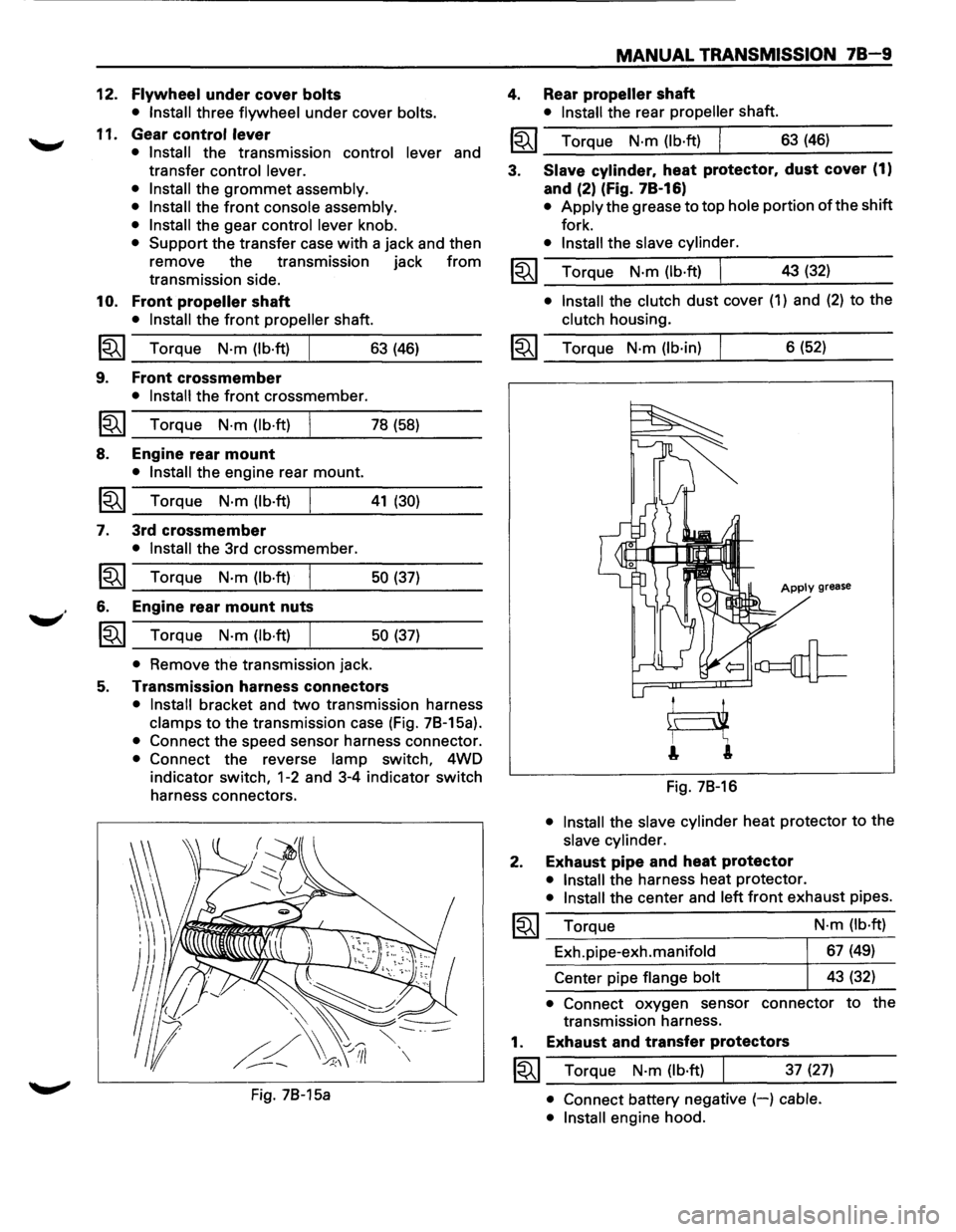
• Install bracket and two transmission harness
clamps to the transmission case (Fig. 78-15a).
• Connect the speed sensor harness connector.
• Connect the reverse lamp switch, 4WD
indicator
switch, 1-2 and 3-4 indicator switch
harness connectors.
Fig. 78-15a
MANUAL TRANSMISSION 78-9
4. Rear propeller shaft
• Install the rear propeller shaft.
I~I __ T_o_rq~u_e __ N_·m~(_lb_·ft~)~ _____ 6_3~(_46~) ____ _
3. Slave cylinder. heat protector. dust cover (1)
and (2) (Fig. 78-16)
• Apply the grease to top hole portion of the shift
fork.
• Install the slave cylinder.
~~~ Torque N·m (lb·ft) I 43 (32) _..:....__~----
• Install the clutch dust cover (1) and (2) to the
clutch housing.
~~~ Torque N·m (lb·in) 6 (52)
Apply grease
Fig. 78-16
• Install the slave cylinder heat protector to the
slave cylinder.
2. Exhaust pipe and heat protector
• Install the harness heat protector.
• Install the center and left front exhaust pipes.
~~~ Torque
Exh.pipe-exh.manifold
Center pipe
flange bolt N·m
(lb·ft)
67 (49)
43 (32)
• Connect oxygen sensor connector to the
transmission harness.
1. Exhaust and transfer protectors
~~~ Torque N·m (lb·ft) 37 (27)
• Connect battery negative (-) cable.
• Install
engine hood.
Page 1145 of 1928
Shift fork (Fig. 7C-23)
• Visually check the surfaces of the shift fork
making contact
with the release bearing for
excessive wear and damage.
• Remove any minor stepping or ah,rasion from
shift fork with an oil stone.
Replace any exhibiting
· ex«?~ssive wear or
damage.
Fig.
7C-23
1••1 INSTALLATION
To install, follow the removal steps in the reverse
order, noting the
following points:
7. Flywheel assembly and crankshaft bearing
§I• Clean and lubricate with grease.
1®..1• Use the installer to install the crankshaft
bearing (Fig. 7C-24).
Installer: J-26516-A
Driver handle: J-8092
Fig.
7C-24
CLUTCH 7C-11
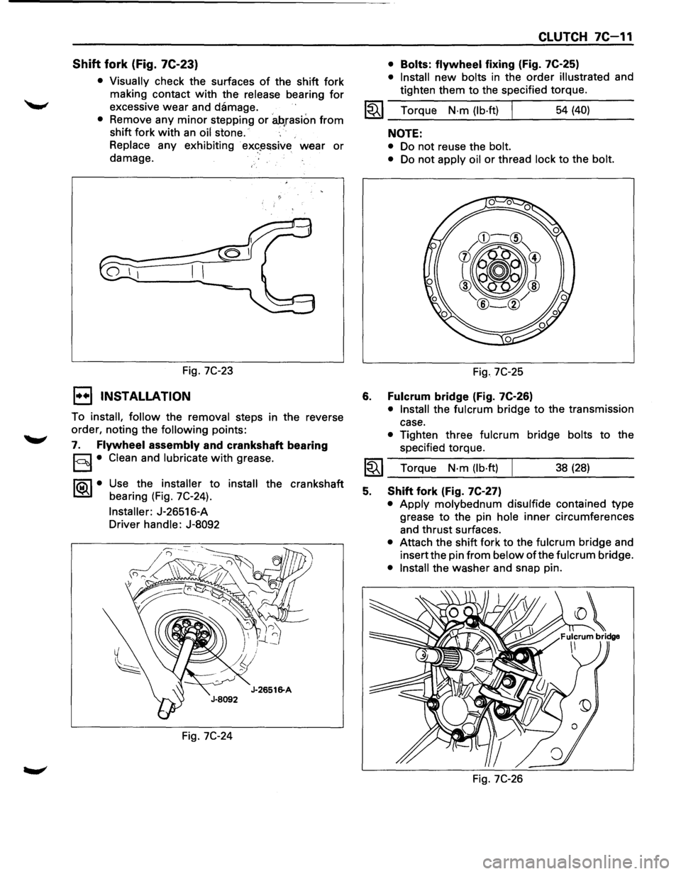
• Bolts: flywheel fixing (Fig. 7C-25)
• Install new bolts in the order illustrated and
tighten them to the specified torque.
1~1 Torque N·m (lb·ft) I 54 (40)
6.
NOTE:
• Do not reuse the bolt.
•
Do not apply oil or thread lock to the bolt.
Fig. 7C-25
Fulcrum bridge (Fig. 7C-26)
• Install the fulcrum bridge to the transmission
case.
• Tighten three fulcrum bridge bolts to the
specified torque.
I~I __ T_o_rq~u_e __ N_·_m~(_lb_·ft_l~ _____ 3_8_(_28_) ____ _
5. Shift fork (Fig. 7C-27)
• Apply molybednum disulfide contained type
grease
to the pin hole inner circumferences
and thrust surfaces.
• Attach the shift fork to the fulcrum bridge and
insert the pin
from below of the fulcrum bridge.
• Install the washer and snap pin.
Fig.
7C-26
Page 1748 of 1928
9J·124 Supplemental Restraint System
DRIVER INFLATOR MODULE
WARNING: SAFETY PRECAUTIONS MUST BE FOLLOWED WHEN HANDLING A DEPLOYED INFLATOR
MODULE(AIR
BAG). AFTER DEPLOYMENT, THE INFLATOR MODULE(AIR BAG} SURFACE MAY CONTAIN A
SMALL AMOUNT OF SODIUM HYDROXIDE, A BY-PRODUCT OF THE DEPLOYMENT REACTION, THAT IS
IRRITATING TO
THE SKIN AND EYES. MOST OF THE POWDER ON THE INFLATOR MODULE (AIR BAG )IS
HARMLESS.
AS A PRECAUTION, WEAR GLOVES AND SAFETY GLASSES WHEN HANDLING A DEPLOYED
INFLATOR MODULE (AIR BAG ), AND WASH YOUR HANDS WITH MILD SOAP AND WATER AFTERWARDS.
WARNING:
WHEN CARRYING A LIVE INFLATOR MODULE (AIR BAG }, MAKE SURE THE BAG AND TRIM
COVER
ARE POINTED AWAY FROM YOU. NEVER CARRY INFLATOR MODULE (AIR BAG )BY THE WIRES OR
CONNECTOR
ON THE UNDERSIDE OF MODULE. IN THE CASE OF AN ACCIDENTAL DEPLOYMENT, THE BAG
WILL THEN DEPLOY WITH MINIMAL CHANCE OF INJURY. WHEN PLACING A LIVE INFLATOR MODULE (AIR
BAG ) ON A BENCH OR OTHER SURFACE, ALWAYS FACE BAG AND TRIM COVER UP, AWAY FROM THE
SURFACE.NEVER REST A STEERING COLUMN ASSEMBLY ON THE STEERING WHEEL WITH THE INFLATOR
MODULE (AIR BAG } FACE DOWN AND COLUMN VERTICAL. THIS IS NECESSARY SO THAT A FREE SPACE
IS PROVIDED TO
ALLOW THE INFLATOR MODULE (AIR BAG} TO EXPAND IN THE UNLIKELY EVENT OF
ACCIDENTAL DEPLOYMENT. OTHERWISE, PERSONAL INJURY COULD RESULT.
NOTE:
In the event deployment has occurred, inspect coil assembly wire for any signs of scorching, melting or any
other damage due to excessive heat.
If the coil has been damaged, replace it.
REMOVAL
1. Disable the SRS. (Refer to "Disabling the SRS "
in this section.)
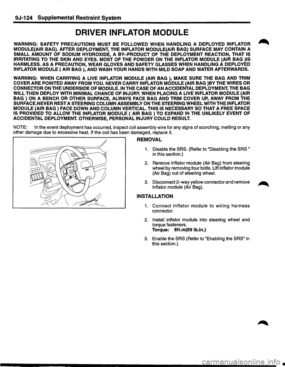
2. Remove inflator module (Air Bag) from steering
wheel by removing four bolts. Lift inflator module
(Air Bag) out of steering wheel.
3. Disconnect 2-way yellow connector and remove ~
inflator module (Air Bag).
INSTALLATION
1. Connect inflator module to wiring harness
connector.
2. Install inflator module into steering wheel and
torque fasteners.
Torque: 8N.m(69 lb.ln.)
3. Enable the SRS (Refer to "Enabling the SRS" in
this section.).
•
Page 1754 of 1928
9J .. 130 Supplemental Restraint System
CAUTION: NEVER APPLY FORCE TO THE
STEERING WHEEL IN DIRECTION OF THE SHAFT
BY USING A HAMMER OR OTHER I~PACT TOOLS
IN AN ATTEMPT TO REMOVE THE STEERING
WHEEL. THE STEERING SHAFT IS DESIGNED AS
AN ENERGY ABSORBING UNIT.
12. Remove steering column cover.
13.
Disconne~t the wiring harness connectors
located base of steering column.
14. Remove the combination switch assembly with
SRScoil.
NOTE: SRS
coil is a part of combination switch
assembly,
which cannot be replaced individually.
Therefore, be sure not to remove the SRS coil from the
combination switch assembly.
15. Remove snap ring.
16. Remove cushion rubber.
17. Disconnect shift
lock cable(For AfT)
18. Disconnect the starter switch harness connector.
Located base of steering column.
19. Remove steering
lock cylinder assembly.
20. Apply a setting mark across the universal joint
and steering shaft to reassemble the parts
in ~
their original position. ~
21. Remove steering column assembly.
NOTE: A setting mark can be easily made if the shaft
is with draw a little by loosening the steering shaft
universal joint.
INSTALLATION
1. Install steering column assembly and align the
setting marks on the universal joint and steering
shaft made during removal.
2. Tighten the steering column fixing bolts( dash
panel side) to the specified torque.
Torque:
19N·m(14 lb·ft.).
3. Tighten the steering column fixing bolts( Pedal
bracket) to the specified torque.
Torque:
17N·m(13 lb·ft.).
4. Tighten the universal joint to the specified
torque.
Torque:
25N·m(181b·ft.).
5. Install steering lock cylinder assembly.
6. Connect shift lock cable(For AfT)
7. Install cushion rubber.
8. Install snap ring.
9. Install the combination switch assembly with
SRScoil.
Page 1845 of 1928
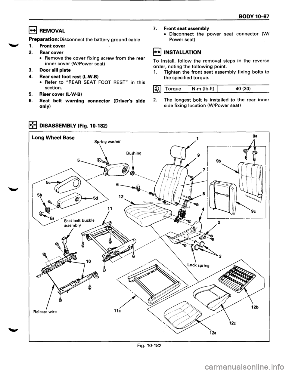
1++1 REMOVAL
Preparation:
Disconnect the battery ground cable
1. Front cover
2. Rear cover
• Remove the cover fixing screw from the rear
inner cover (W/Power seat)
3. Door sill plate
4. Rear seat foot rest (l·W·B)
• Refer to "REAR SEAT FOOT REST" in this
section.
5. Riser cover (L·W·B)
6. Seat belt warning connector (Driver's side
only)
1•!•1 DISASSEMBLY (Fig. 10-182)
Long Wheel Base Spring washer
Bushing
5
Release wire
BODY 10-87
7. Front seat assembly
•
Disconnect the power seat connector (W/
Power seat)
I++IINSTALLATION
To install, follow the removal steps in the reverse
order,
noting the following point.
1. Tighten the front seat assembly fixing bolts to
the specified torque.
~~~ Torque N-m (lb·ft) 40 (30)
2. The longest bolt is installed to the rear inner
side fixing location (W/Power seat)
9a
Fig. 10-182
Page 1861 of 1928
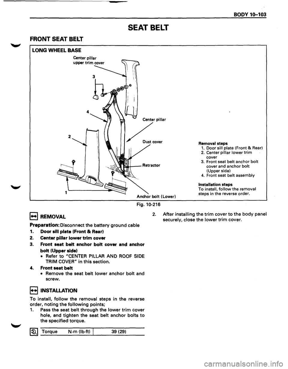
FRONT SEAT BELT
LONG WHEEL BASE
2
1
Center pillar
upper trim cover
SEAT BELT
Center pillar
~ .....
Anchor bolt (Lower)
Fig. 10-216
BODY 1Q-103
Removal steps 1. Door sill plate (Front & Rear)
2. Center pillar lower trim cover 3. Front seat belt anchor bolt cover and anchor bolt (Upper side) 4. Front seat belt assembly
Installation
steps
To install, follow the removal
steps in the reverse order.
B REMOVAL 2. After installing the trim cover to the body panel
securely, close
the lower trim cover.
Preparation: Disconnect the battery ground cable
1. Door sill plate (Front & Rear)
2. Center pillar lower trim cover
3. Front seat belt anchor bolt cover and anchor
bolt (Upper side)
• Refer to "CENTER PILLAR AND ROOF SIDE
TRIM COVER" in this section.
4. Front seat belt
• Remove the seat belt lower anchor bolt and
screw.
I••IINSTALLATION
To install, follow the removal steps in the reverse
order, noting the
following points;
1. Pass the seat belt through the lower trim cover
hole, and tighten the seat belt anchor bolts to
the specified torque.
~~~ Torque N·m (lb·ft) I 39 (29)
Page 1862 of 1928
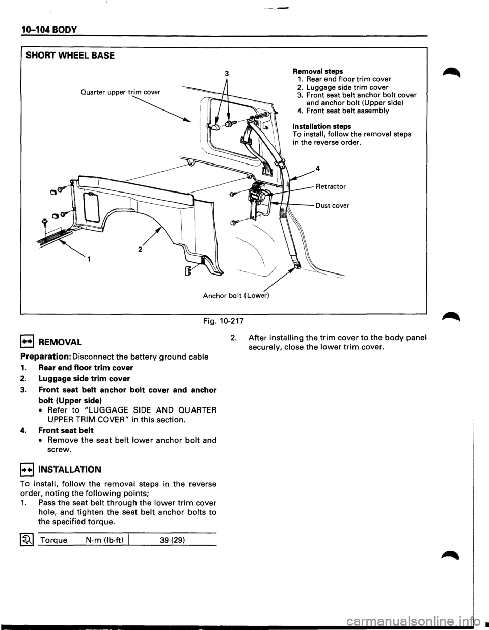
----
10-104 BODY
SHORT
WHEEL BASE
3 Removal steps 1. Rear end floor trim cover 2. Luggage side trim cover 3. Front seat belt anchor bolt cover
and anchor bolt (Upper side)
4. Front seat belt assembly
Installation steps
To install, follow the removal steps
in the reverse order.
4
Retractor
Anchor bolt (Lower)
Fig. 10-217
1++1 REMOVAL
Preparation: Disconnect the battery ground cable
1. Rear end floor trim cover
2. Luggage side
trim cover
3.
Front seat belt anchor bolt cover and anchor
bolt (Upper side)
• Refer to "LUGGAGE SIDE AND QUARTER
UPPER TRIM COVER" in this section.
4. Front seat belt
• Remove the seat belt lower anchor bolt and
screw.
I••IINSTALLATION
To install, follow the removal steps in the reverse
order,
noting the following points;
1. Pass the seat belt through the lower trim cover
hole, and tighten the seat belt anchor bolts to
the specified torque.
~~~ Torque N-m (lb·ft) 39 (29)
2. After installing the trim cover to the body panel
securely, close
the lower trim cover.
•
Page 1864 of 1928
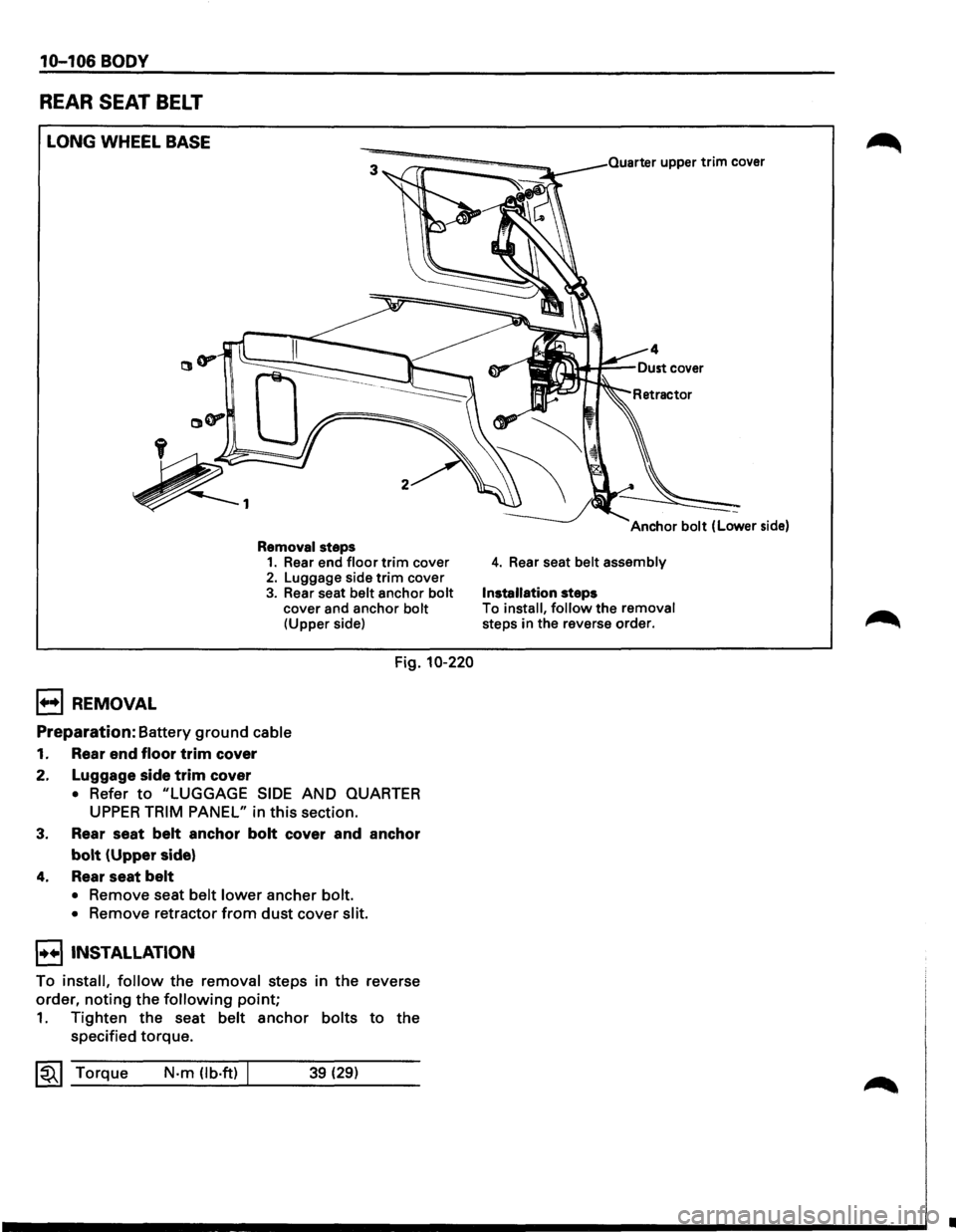
10-106 BODY
REAR SEAT BELT
LONG WHEEL BASE
B REMOVAL
Removal steps 1. Rear end floor trim cover 2. Luggage side trim cover
3. Rear seat belt anchor bolt cover and anchor bolt (Upper side)
Fig. 10-220
Preparation: Battery ground cable
1. Rear end floor trim cover
2. Luggage side
trim cover
• Refer to "LUGGAGE SIDE AND QUARTER
UPPER TRIM PANEL" in this section.
3. Rear seat belt anchor bolt cover and anchor
bolt (Upper side)
4. Rear seat belt
• Remove seat belt lower ancher bolt.
•
Remove retractor from dust cover slit.
I••IINSTALLATION
To install, follow the removal steps in the reverse
order,
noting the following point;
1. Tighten the seat belt anchor bolts to the
specified torque.
~~~ Torque N·m (lb.ft) 39 (29)
Quarter upper trim cover
4. Rear seat belt assembly
Installation steps
To install, follow the removal steps in the reverse order.
•