air condition ISUZU TROOPER 1995 Workshop Manual
[x] Cancel search | Manufacturer: ISUZU, Model Year: 1995, Model line: TROOPER, Model: ISUZU TROOPER 1995Pages: 1928
Page 1212 of 1928
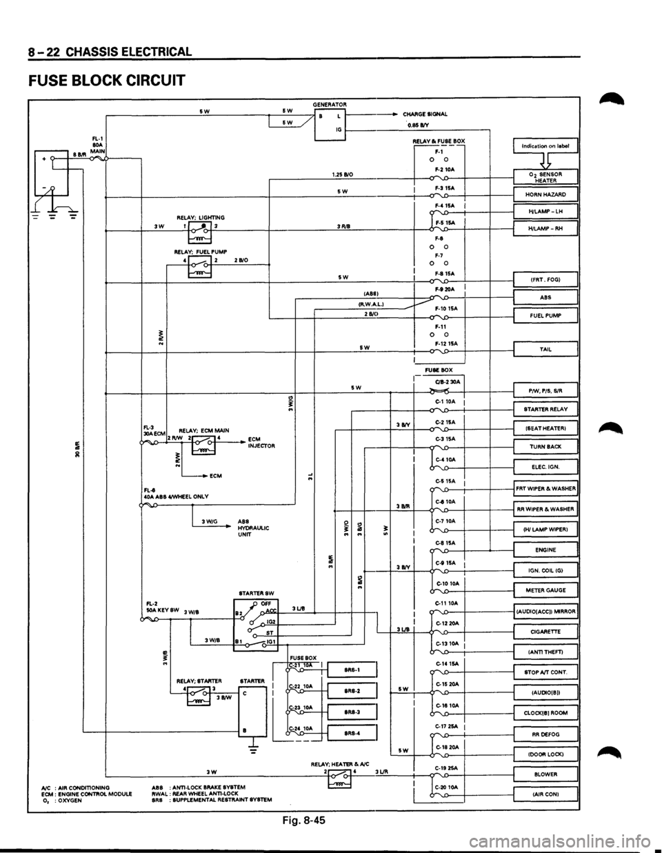
8-22 CHASSIS ELECTRICAL
FUSE BLOCK CIRCUIT
GENERATOR -------------------~s~w~------------~~s~w~--~~~~ r- / B L 1------CHARGE SIGNAL &W _/
FL-1 80A .-----, B 11.'1 MAIN
+ Lt--
l£h
~----/ IG~----------~O~.$~B/V~-----------,
3W REL~HT1NG 1J ---'"~L 3
RELA~PUMP 4 1...---. 12 2 B/0
1.25 B/0
SW
3RJ8
5W
~~~·~ F-1 0 0 F-2 10A
I F-315A
F-8
0 0 F-7 0 0 F-81SA
F-920A
9;nlaool
I
Oz SENSOR HEATER
HORN HAZARD
H/LAMP-LH
H/LAMP-RH
(FRT. FOG)
lABS) -I ABS
I ,--------__:<;;:R·.:.:W.::..Acc·L;;:-1 ____ ----Jv F-10 1SA 2 810
I
~ECM RELAY; ECM MAIN ¢~,...,..J>--+2'-'RIW~_::2~1-o.....-<:>-f-·4.:._ __ _. ~J~CTOR
L...-_.ECM
FL-t 40A ABS 4/WHEEL ONLY
"
.... ...
SW
5W
3 8IY
F-11 0 0 F-1215A
~------' FUSE BOX
CIB-2 30A ~.,.;
C-110A :
C-215A
C-31SA
C-410A
I
J
FUEL PUMP
TAIL
P/W, PIS. SIR
STARTER RELAY
(SEAT HEATER)
TURN BACK
ELEC.IGN.
e-s
15A 1 ""'-.0---t-----+----il FRT WIPER & WASHER
"""' -
I 3W/G
C-810A '---f-+----+.:3.:BIR::::..+---¢""''-£>---i-----f-----jl RR WIPER & WASHER
ABS HYORAULIC UNIT
STARTERSW
FL-2 _JJ OFF
~ ...
..:..AKEYSW 3 W/B ay ' o.N". 3UB
~~--~--~,~------~-0 ~~IG~2Y-----------~ o-: ST 3W/B 81 -.,IG1
FUSE BOX
I
I g1~ 1 J'-:::s:R:s-:1 =I RELAY; STARTER
STARTER I r-
L~---'~-j.t
I I 3UB
sw
C-710A
~';::--~--~-'---~~~HI~LA~M~P~W~IP~E~R~l~~ C-81SA ""'-'>--1---...__---i ENGINE
C-111SA I J~======~l IGN. COIL (G)
C-10 10A
C-1110A
k'-1:>----t----t
~==~I
METER GAUGE
""''-£>---f----------1 (AUDIO[ACC)) MIRROR
C-12 20A
::...1310A I
C-141SA -r"\'-1)----f----t
C-15 20A L,-.
CIGARETTE
(ANTITHEFT)
STOP A/T CONT.
(AUDIO[ B))
C-1810A """"-'-.0---f----------t_j CLOCK[B) ROOM
L---+------------------------iB lt~;_ ~=~~~:~:~::~~~: C-17 2SA I
G1820A
RR DEFOG
= sw (DOOR LOCK) RELAY; HEATER &A/C .:._ __________________ .:.:3~W'-'---------------------~2to~.....-4 3UR C-19 2SA ...... BLOWER
A/C : AIR CONDITIONING ECM : ENGINE CONTIIOL MODULE 0, :OXYGEN ABS
:ANTI-LOCK
BRAKE BYBTEM
RWAL: REAR WHEEL ANTI-LOCK BRB : SUPPLEMENTAL RESTRAINT SYSTEM
C-20 10A (AIR CON)
Fig. 8-45
•
Page 1217 of 1928
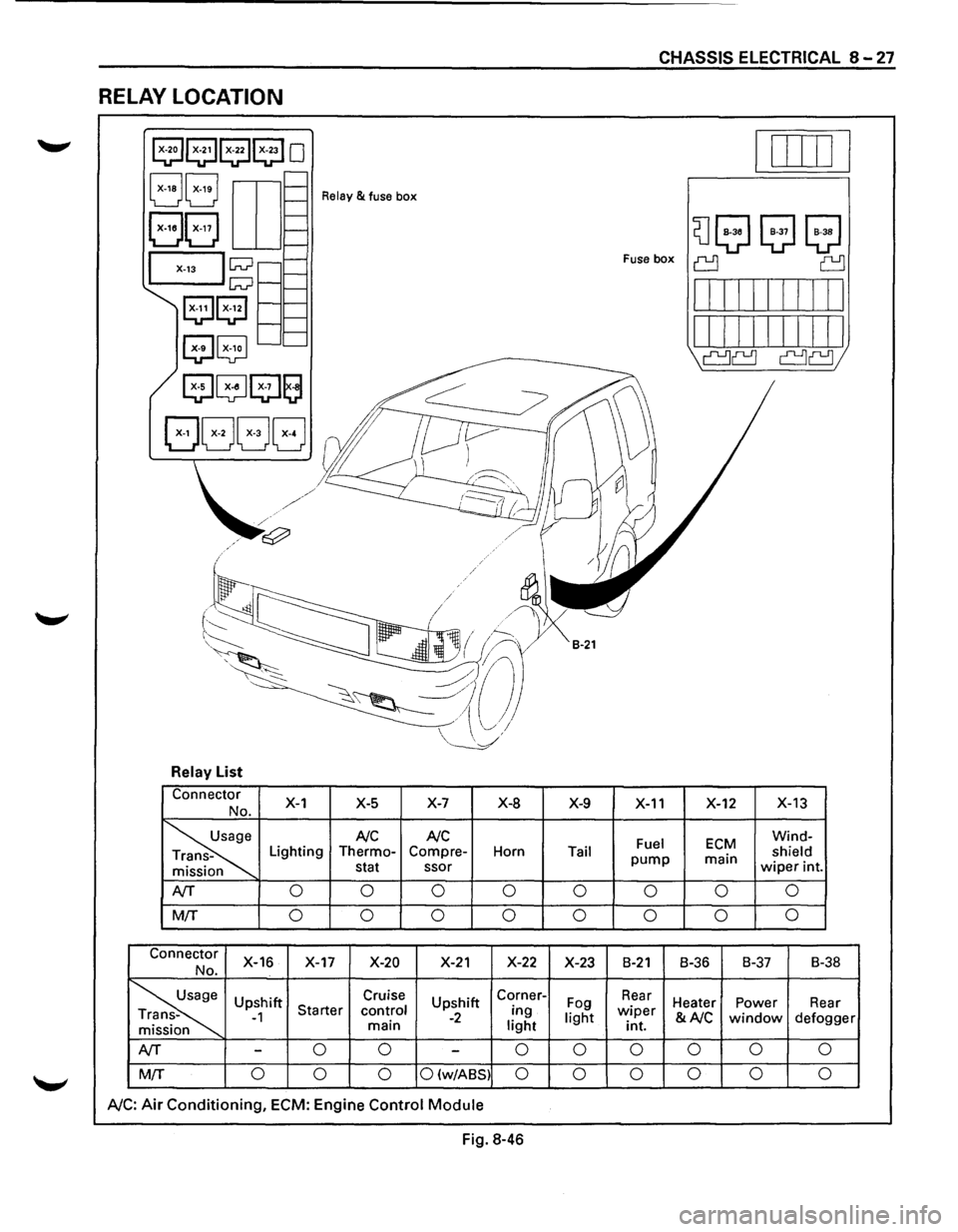
RELAY LOCATION
Relay & fuse box
Relay List
Connector X-1 X-5 X-7
X-8
No.
~
NC NC Lighting Thermo-Com pre-
Horn -stat ssor
n
NT 0 0 0 0
M(f 0 0 0
0
Connector
X-16 X-17 X-20 X-21 X-22
No.
~
Upshift Cruise Upshift Corner-
-1 Starter control -2 ing -main light n
NT -0 0 -0
M!f 0 0 0 0(w/A8S) 0
AJC: Air Conditioning, ECM: Engine Control Module
Fig. 8-46
B-21
X-9
Tail
0
0
X-23
Fog
light
0
0
CHASSIS ELECTRICAL 8-27
Fuse box
X-11
Fuel pump
0
0
8-21
II]]]J I
~8~8
c:J c:J
11111111111
111111
IIIII
BB a B
X-12 X-13
ECM Wind-
main shield wiper int.
0
0
0 0
8-36
8-37
8-38
Rear Heater Power Rear
wiper int. &NC window defogger
0
0 0
0
0 0 0
0
Page 1218 of 1928
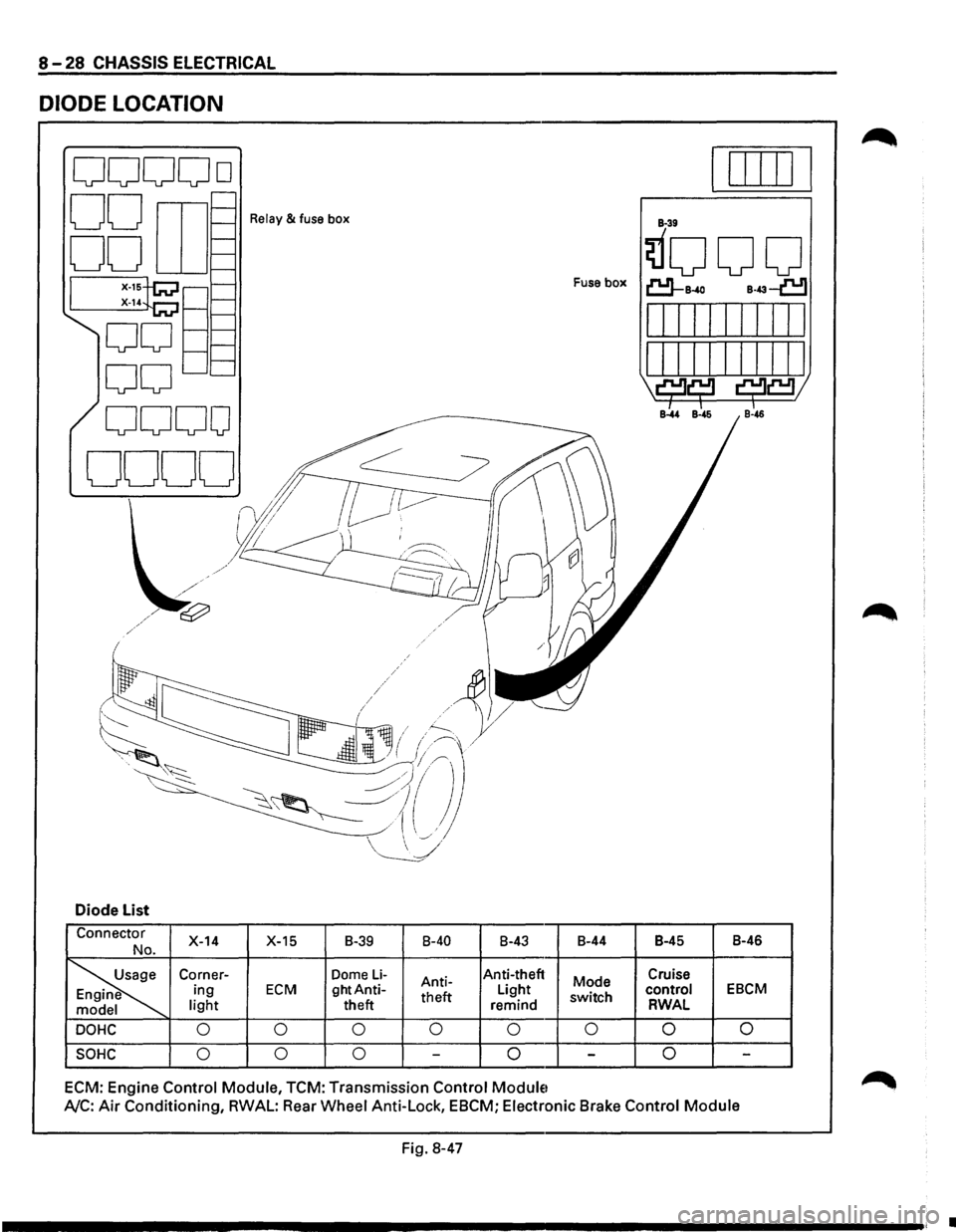
8-28 CHASSIS ELECTRICAL
DIODE LOCATION
Relay & fuse box
Fuse box
Diode List
Connector X-14
X-15 B-39 8-40 8-43 8-44
B-45 8-46 No.
~
Corner-Dome Li-Anti-Anti-theft
Mode Cruise ing ECM ghtAnti-
theft Light
switch control EBCM
light
theft remind RWAL
DOHC 0
0 0 0
0 0 0 0
SOHC 0
0 0 -0 -0 -
ECM:
Engine Control Module, TCM: Transmission Control Module1
A/C: Air Conditioning, RWAL: Rear Wheel Anti-Lock, EBCM; Electronic Brake Control Module
Fig. 8-47
•
Page 1220 of 1928
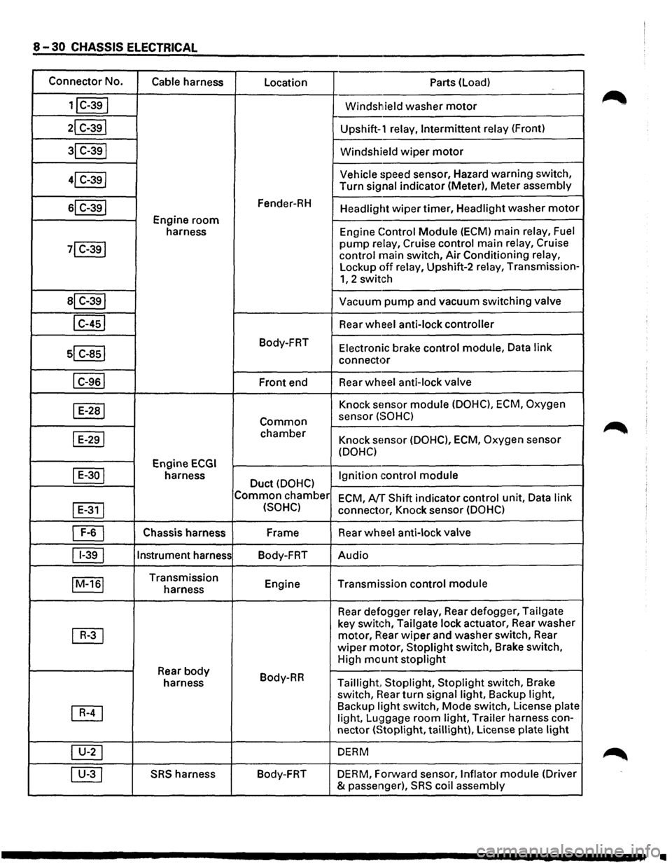
8-30 CHASSIS ELECTRICAL
Connector No.
Cable harness
Location Parts (load)
1jC-39I Windshield washer motor
21 C-391 Upshift-1 relay, Intermittent relay (Front)
31 C-391 Windshield wiper motor
41 C-39j Vehicle speed
sensor, Hazard warning switch,
Turn
signal indicator (Meter), Meter assembly
sl C-391 Fender-RH Headlight wiper timer, Headlight washer motor
Engine room
harness Engine Control Module (ECM)
main relay, Fuel
71 C-391 pump relay, Cruise control main relay, Cruise
control main switch, Air Conditioning relay,
Lockup off relay, Upshift-2 relay, Transmission-
1, 2 switch
al C-391 Vacuum pump and vacuum switching valve
I C-451 Rear wheel anti-lock controller
sl c-asl
Body-FRT Electronic brake control module, Data link
connector
I C-961 Front end Rear wheel
anti-lock valve
I E-281 Knock sEmsor module (DOHC), ECM, Oxygen
Common sensor (SOHC)
I E-291 chamber Knock sensor (DOHC), ECM, Oxygen sensor
(DOHC)
Engine
ECGI
I E-30 I harness Duct (DOHC) Ignition control
module
Common chamber
ECM, AfT Shift indicator control unit, Data link
I
E-311 (SOHC) connector, Knock sensor (DOHC)
~ Chassis harness Frame
Rear wheel anti-lock valve
11-391 Instrument
harness
Body-FRT Audio
IM-161 Transmission
Engine Transmission control module harness
Rear defogger
relay, Rear defogger, Tailgate
~
key switch, Tailgate lock actuator, Rear washer
motor, A:ear wiper and washer switch, Rear
wiper motor, Stoplight switch, Brake switch,
High
mount stoplight
Rear body Body-RR
harness Taillight, Stoplight, Stoplight switch, Brake
switch,
near turn signal light, Backup light,
~
Backup light switch, Mode switch, License plate
light, Lu!;)gage room light, Trailer harness con-
nector
(Stoplight, taillight), License plate light
~ DERM
00 SRS harness Body-FRT
DERM, Forward sensor, Inflator module (Driver
& passenger),
SRS coil assembly
•
Page 1235 of 1928
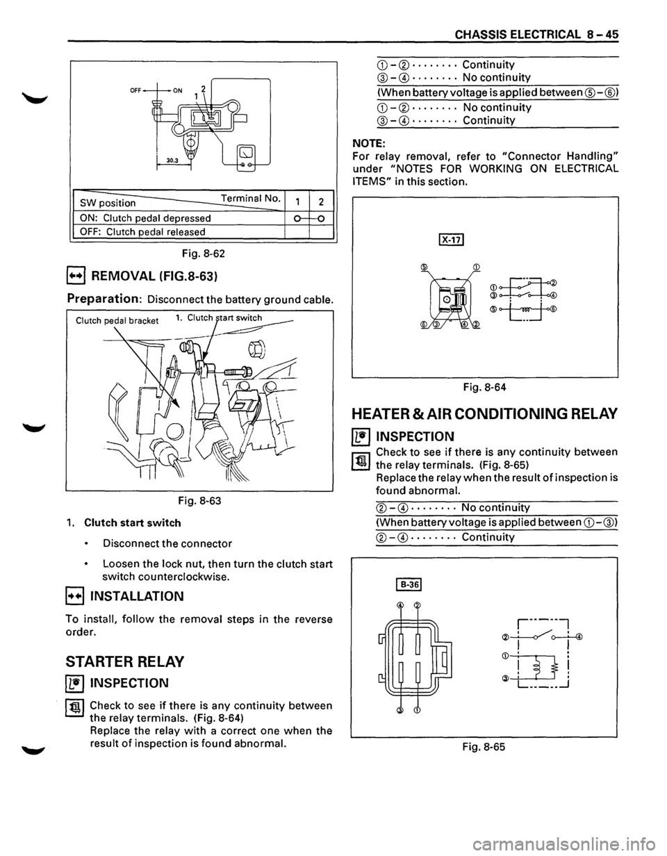
OFF
SW position Terminal No.
ON: Clutch pedal depressed
OFF: Clutch pedal released
Fig. 8-62
B REMOVAL (FIG.S-63)
2
Preparation: Disconnect the battery ground cable.
Fig. 8-63
1. Clutch start switch
Disconnect the connector
Loosen the lock nut, then turn the clutch start
switch counterclockwise.
B INSTALLATION
To install, follow the removal steps in the reverse
order.
STARTER RELAY
~ INSPECTION
ltgl Check to see if there is any continuity between
the relay terminals. (Fig. 8-64)
Replace the relay with a correct one when the
result of inspection is found abnormal.
CHASSIS ELECTRICAL 8-45
CD-®······ · · Continuity
@-G)· . · · · · .. No continuity
(When battery voltage is applied between®-@)
CD-®· · · · · · · · No continuity
@-G)· · · · · · · · Continuity
NOTE:
For relay removal, refer to "Connector Handling"
under "NOTES FOR WORKING ON ELECTRICAL
ITEMS"
in this section.
®JI
@~
®
Fig. 8-64
HEATER & AIR CONDITIONING RELAY
~ INSPECTION
l'fll Check to see if there is any continuity between
~ the relay terminals. (Fig. 8-65)
Replace the relay when the result of inspection is
found abnormal.
®-G) ..... · .. No continuity
(When battery voltage is applied between CD-@)
®-G) .... · · .. Continuity
Fig. 8-65
Page 1237 of 1928
CHASSIS ELECTRICAL 8-47
ENGINE CONTROL MODULE (ECM)
GENERAL DESCRIPTION
The ECM is used to control the fuel system of the
vehicle, especially in controlling the following items.
1. FUEL CONTROL
The amount of fuel and air sent into the combus
tion chamber is controlled by controlling the fuel
sent through the injector.
2. ELECTRIC FUEL PUMP (INSTALLED IN
THE FUEL TANK)
The in-tank fuel pump is controlled by the ECM.
When starter switch is turned on, the pump will
run for 2 seconds, then stop unless the engine is
cranking
or running.
3. IGNITION CONTROL
The system is controlled by the spark timing con
trol function of the ECM.
4. CIRCULATION OF EXHAUST GAS
The system controls the formation of NOx by
returning a small amount of exhaust gas to the
intake manifold
through the control valve.
'-" lAC: Idle air control
5. CONTROL OF AIR CONDITIONING (A/C)
For improved engine idling performance, the sys
tem controls the operation of the air conditioner
by regulating the
clutch operation ofthe A/C com
pressor in accordance
with changes in operation.
6. IDLE AIR CONTROL
The system controls the lAC Valve for the desired
idle speed in accordance
with changes in
operation.
7. DIAGNOSIS OF TROUBLES
When a sensor detects any signal that the ECM is
in
an abnormal condition, the ECM turns on the
malfunction
indicator (CHECK ENGINE) light in
the meter, and stores at the same
time the corre
sponding diagnostic
trouble code (DTC) in the
memory to indicate to which system or circuit the
trouble represented by the
DTC belongs.
The ECM inspection connector (data link connec
tor) is used
to retrieve the DTCs stored from the
ECM.
Refer to Section 6 "ENGINE DIAGNOSIS" for de
tails.
Page 1241 of 1928
w " ~~ O.SLJY ~ ..
2"' a~ u$ ~f~ ~~ ~g~
FENDER-RH II
DUCT II
~~~~~II
DUCT II
INTAKE AIR TEMPERATURE SENSOR
~~ 0~
a; d
0.89
C-1 A&
THROTTLE POSITION
SENSOR
... 5! ., .. ::> 0: ~
m
0.85LIO
~ a d d
li~Ui"o:i UOlUCJI> i;i;i:b ~wuw "'"" ~ ~ g g
"' il " Ill
13
§
; w 0 0: .. 5N ~;:; 8<:1 d~ u"' ~~ ~~ ~~ z< ., .. ~g ~g
~ § :;1 ~ d
0: " Ill d
ENGINE COOLANT
TEMPERATURE
SENSOR
CHASSIS ELECTRICAL 8-51
~ ~ ~w _.,
i£ ~g
~ i ;zf d
d
IIi ~ d .. :b
~~ ~g
~
"' ~ 5I d "'
13 12 H-6 H-6
.. ~ "' ~ il il
!
! ! ~
~ ~ I ~ CD ! ! ~
i
i
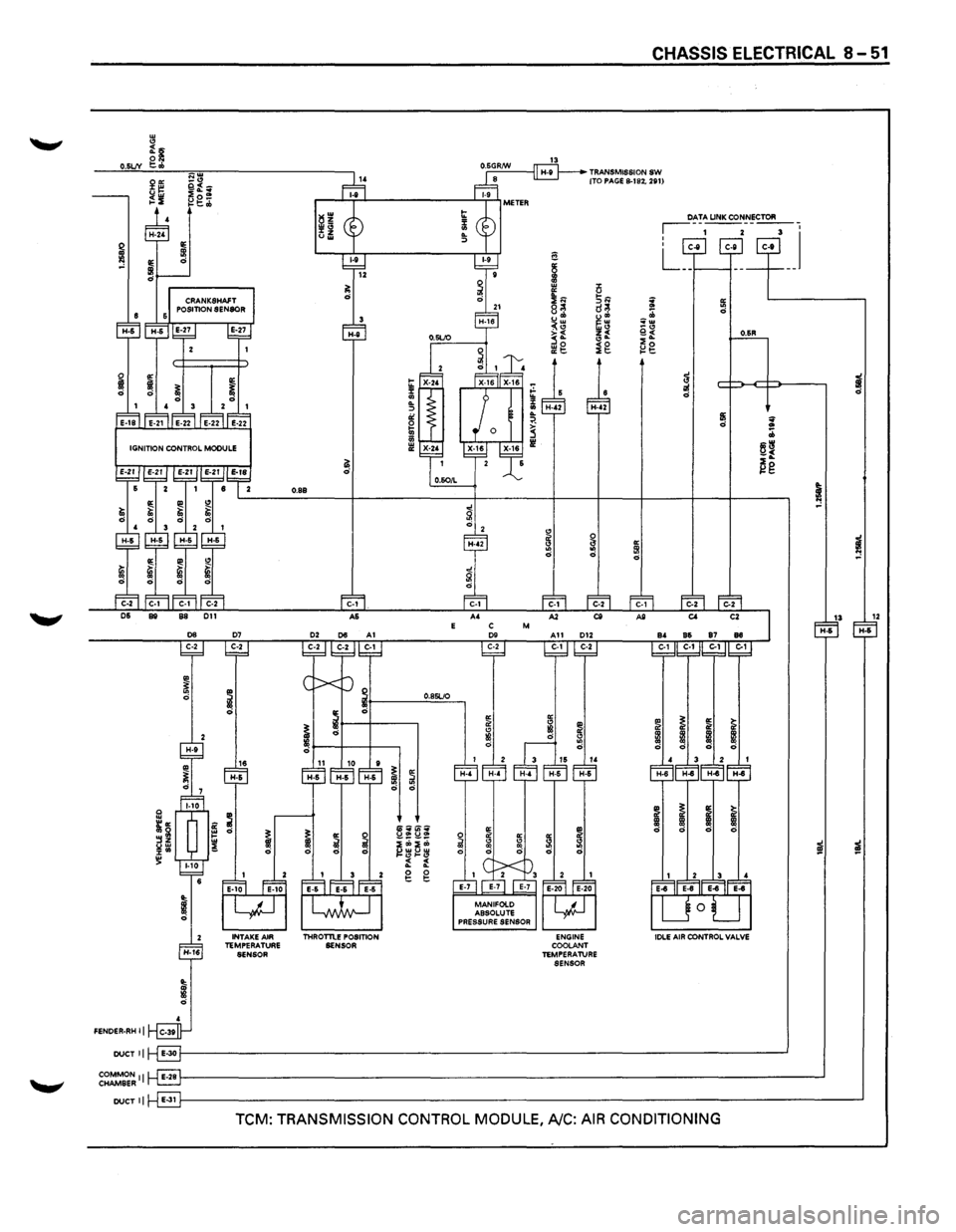
TCM: TRANSMISSION CONTROL MODULE, A/C: AIR CONDITIONING
Page 1243 of 1928
0.5 LJV
E C M
.. ~ ~ g ~ ::r <3 ::! ~ ~ IB Ill d 0 d 0.85 LJO d
16 10 ~ ~ H-6 ~ ~
: : 3 ~ ~ ;;; ;;; .. 3~ ~~ ~ " 0 ~ I -f -:
~I
~g~g
INTAKE AIR THROTTLE TEMPERATURE POSITION SENSOR
SENSOR
'ENDER-RH II
f-'0""·5,;G,RIN!!!!.__,~ TRANSMISSION SW (TO PAGE 8-182. 281)
a
~ .. % IE u 21<1 3~ i 8<=~
~= u .. ;;;
~~ '"'" ~~
_.., j§L e.~ 2o ll!g ig l:!t::
a: ~ i <3 <3 IB .. IB d
d
d
a: a: ~ ~ <3 " .. .. .. d d ~ ~
CHASSIS ELECTRICAL 8 ... 53
~ ... .. d
~ ..
~
~ .. ~
i IB d
~ .. ~
a: .. d
13 1Z H-5 H-5
i IB d
iil iil
~ .. .. 0
COMMON{::~------------------------------------------------------------------------------------------~ CHAMBER r·-l::.:!!J
II E-311-'----------------------------------------------------------------------------------------------~
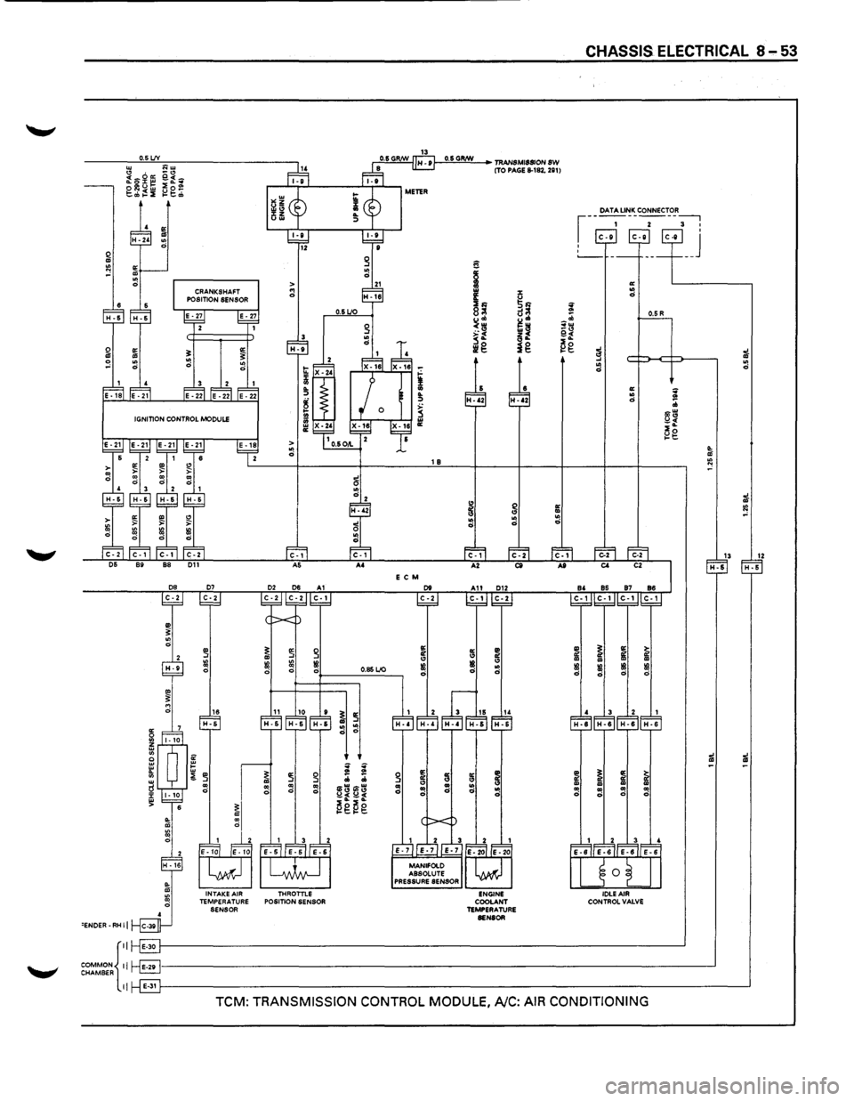
TCM: TRANSMISSION CONTROL MODULE, A/C: AIR CONDITIONING
Page 1260 of 1928
I ..
8 -70 CHASSIS ELECTRICAL
When placing a live inflator module on a bench
or other surface, always face the bag and trim
cover up, away from the surface. This is neces
sary so that a free space is provided to allow the
air bag to expand in the unlikely event of acci·
dental
deployment.
4. Steering wheel
• Refer to STEERING WHEEL REPLACEMENT in
Section 3F4.
5. Lighting switch (Combination switch)
• Disconnect the switch connector.
• Remove four screws.
• Remove the lighting switch together with SRS
coil assembly.
'\f CAUTION:
Do not remove SRS coil assembly from the com·
bination switch assembly.
E) INSTALLATION
To install, follow the removal steps in the reverse
order, noting the
following points.
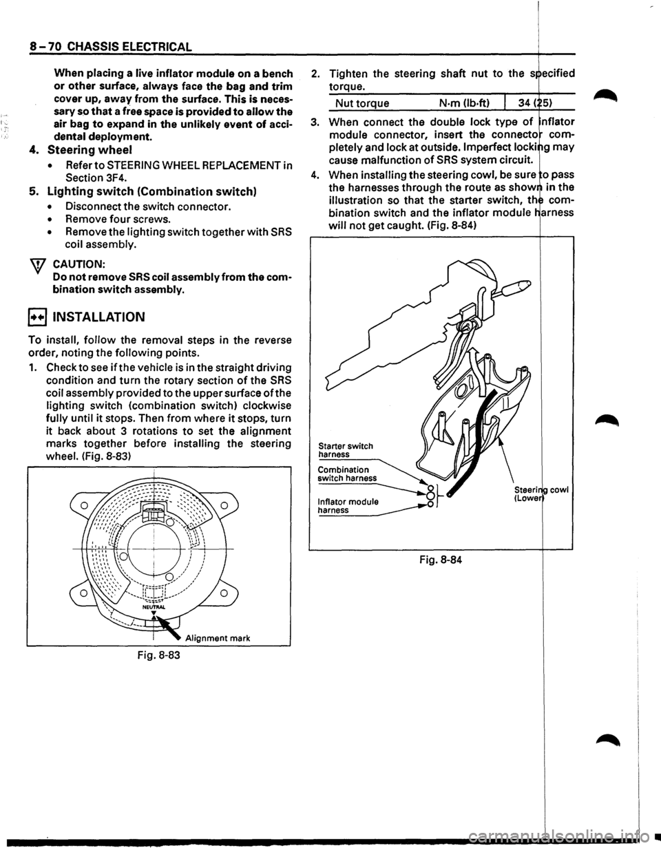
1. Check to see if the vehicle is in the straight driving
condition and turn the rotary section of the SRS
coil assembly provided to the upper surface ofthe
lighting switch (combination switch) clockwise
fully until it stops. Then from where it stops, turn
it back about 3 rotations to set the alignment
marks together before installing the steering
wheel. (Fig. 8-83)
Alignment mark
Fig. 8-83
2. Tighten the steering shaft nut to the s ecified
torque.
Nut torque N·m (lb.ft)
3. When connect the double lock type of nflator
module connector, insert the connecto com
pletely
and lock at outside. Imperfect locki g may
cause malfunction of SRS system circuit.
4. When installing the steering cowl, be sure o pass
the harnesses
through the route as show in the
illustration so that the starter switch, th com
bination switch and the inflator module
will not get caught. (Fig. 8-84)
Starter switch
harness
Combination
switch harness
~~ ~
Fig. 8-84
cowl
•
Page 1338 of 1928
8-148 CHASSIS ELECTRICAL
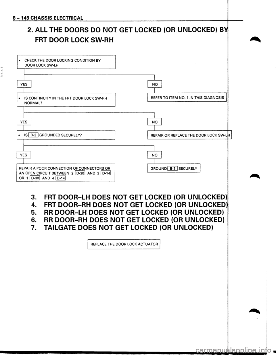
2. ALL THE DOORS DO NOT GET LOCKED (OR UNLOCKED) B~
FRT DOOR LOCK SW-RH
• CHECK THE DOOR LOCKING CONDITION BY
DOOR LOCK SW-LH
I
I
YES I
I
• IS CONTINUITY IN THE FAT DOOR LOCK SW-RH
NORMAL?
I
I
YES I
I
• IS(]}] GROUNDED SECURELY?
I
I
YES I
1
REPAIR A POOR CONNECTION OF CONNECTORS OR
AN OPEN CIRCUIT BETWEEN 2 I D-301 AND 31 D-141
OR 1 I D-301 AND 41 D-141
I
I
I NO I
I
I REFER TO ITEM NO. 1 IN THIS DIAGNOSIS I
I
I NO I
I
I REPAIR OR REPLACE THE DOOR LOCK SW-L -1 I
I
I NO I
I
I GROUND[]]]SECURELY I
3. FRT DOOR-LH DOES NOT GET LOCKED (OR UNLOCKED)
4. FRT DOOR-RH DOES NOT GET LOCKED (OR UNLOCKED
5. RR DOOR-LH DOES NOT GET LOCKED (OR UNLOCKED)
6. RR DOOR-RH DOES NOT GET LOCKED (OR UNLOCKED)
7. TAILGATE DOES NOT GET LOCKED (OR UNLOCKED)
I REPLACE THE DOOR LOCK ACTUATOR I
..