wheel ISUZU TROOPER 1995 Workshop Manual
[x] Cancel search | Manufacturer: ISUZU, Model Year: 1995, Model line: TROOPER, Model: ISUZU TROOPER 1995Pages: 1928
Page 509 of 1928
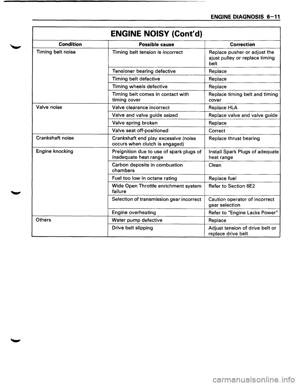
ENGINE DIAGNOSIS 6-11
ENGINE NOISY (Cont'd)
Condition Possible cause Correction
Timing belt noise
Timing belt tension is incorrect Replace pusher or adjust the
ajust
pulley or replace timing
belt
Tensioner bearing defective Replace
Timing belt defective Replace
Timing wheels defective Replace
Timing belt comes in contact with Replace timing belt and timing
timing cover
cover
Valve noise Valve clearance incorrect Replace HLA
Valve and valve guide seized Replace valve and valve guide
Valve spring broken Replace
Valve
seat off-positioned
Correct
Crankshaft noise
Crankshaft end
play excessive (noise Replace thrust bearing
occurs
when clutch is engaged)
Engine knocking
Preignition due
to use of spark plugs of Install Spark Plugs of adequate
inadequate heat range
heat range
Carbon deposits in combustion
Clean
chambers
Fuel too low in octane rating Replace fuel
Wide Open Throttle enrichment system
Refer to Section 6E2
failure
Selection
of transmission gear incorrect Caution operator of incorrect
gear
selection
Engine overheating
Refer to "Engine Lacks Power"
Others Water
pump defective Replace
Drive belt slipping Adjust tension of drive belt or
replace drive belt
Page 539 of 1928
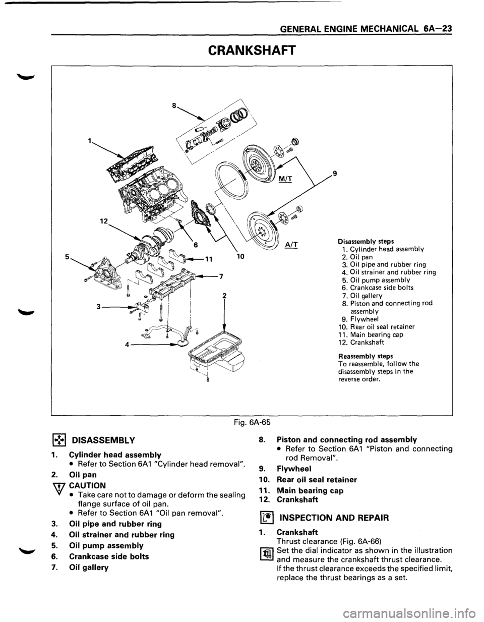
GENERAL ENGINE MECHANICAL 6A-23
CRANKSHAFT
9
5
Disassembly steps
1. Cylinder head assembly
2. Oil pan
3. Oil pipe and rubber ring
4. Oil strainer and rubber ring
5.
Oil pump assembly 6. Crankcase side bolts
7. Oil gallery 8. Piston and connecting rod
assembly 9. Flywheel
10. Rear oil seal retainer 11. Main bearing cap
12. Crankshaft
Reassembly steps To reassemble, follow the disassembly steps in the reverse order.
Fig. 6A-65
1 .. !,.1 DISASSEMBL V
1. Cylinder head assembly
•
Refer to Section 6A1 "Cylinder head removal".
2. Oil pan
\i7 CAUTION
~ • Take care not to damage or deform the sealing
flange
surface of oil pan.
• Refer to Section 6A1 "Oil pan removal".
3. Oil pipe and rubber ring
4. Oil strainer and rubber ring
5. Oil pump assembly
6. Crankcase side bolts
7. Oil gallery
8. Piston and connecting rod assembly
•
Refer to Section 6A 1 "Piston and connecting
rod
Removal".
9. Flywheel
10.
Rear oil seal retainer
11. Main bearing cap
12. Crankshaft
IL•I INSPECTION AND REPAIR
1. Crankshaft
Thrust clearance (Fig. 6A-66)
l'fil Set the dial indicator as shown in the illustration
~ and measure the crankshaft thrust clearance.
If the thrust clearance exceeds the specified limit,
replace
the thrust bearings as a set.
Page 544 of 1928
6A-28 GENERAL ENGINE MECHANICAL
Fig. 6A-80
/
Fig. 6A-81
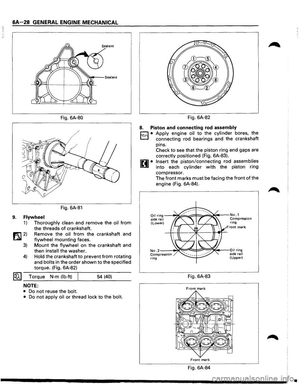
9. Flywheel
1) Thoroughly clean and remove the oil from
the threads
of crankshaft.
1!t1 2) Remove the oil from the crankshaft and
LQI flywheel mounting faces.
3) Mount the flywheel on the crankshaft and
then
install the washer.
4) Hold the crankshaft to prevent from rotating
and
bolts in the order shown to the specified
torque. (Fig. 6A-82)
~~~ Torque N·m (lb·ft) I ___ ___,_ ___ _ 54 (40)
NOTE:
• Do not reuse the bolt.
•
Do not apply oil or thread lock to the bolt.
Fig. 6A-82
8. Piston and connecting rod assembly
D • Apply engine oil to the cylinder bores, the
l:J connecting rod bearings and the crankshaft
pins. Check to see that the piston ring end gaps are
correctly positioned (Fig. 6A-83).
Insert the piston/connecting rod assemblies
into each cylinder with the piston ring
compressor. The
front marks must be facing the front of the
engine (Fig. 6A-84).
Oil ring ---~====-~::F::::::.===~~t---No. 1
side rail Compression (Lower) ring Front mark
No .2--~~:::::=:e!::::!-;::::!!;~~·-Oil ring
Compression side rail ring (Upper)
Fig. 6A-83
Front mark
Front mark
Fig. 6A-84
•
Page 553 of 1928
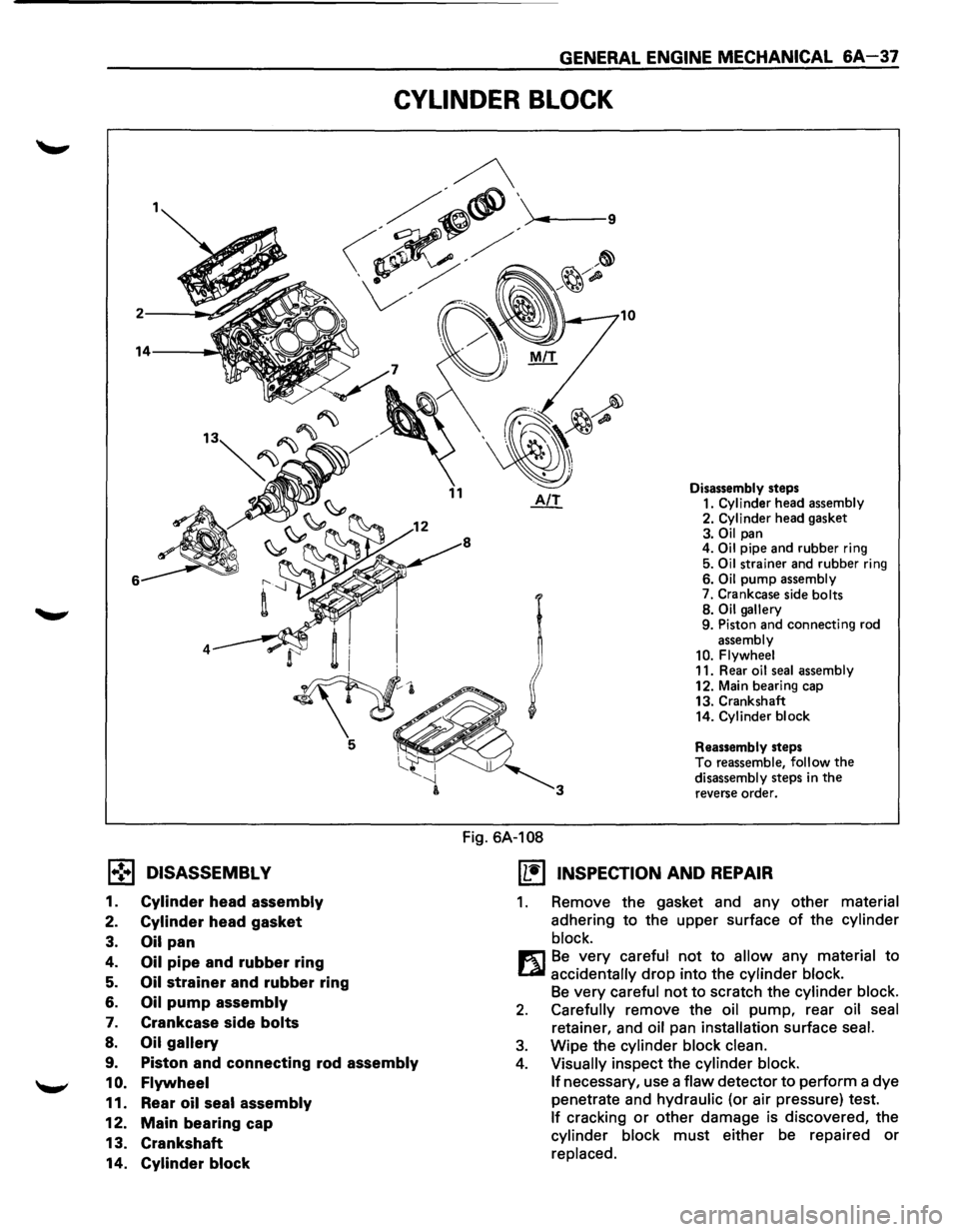
GENERAL ENGINE MECHANICAL 6A-37
CYLINDER BLOCK
1.,!•1 DISASSEMBL V
1. Cylinder head assembly
2. Cylinder head gasket
3. Oil pan
4. Oil pipe and rubber ring
5. Oil strainer and rubber ring
6. Oil pump assembly
7. Crankcase side bolts
8. Oil gallery
9. Piston and connecting rod assembly
1 0. Flywheel
11. Rear oil seal assembly
12. Main bearing cap
13. Crankshaft
14.
Cylinder block
Fig. 6A-108
Disassembly steps
1. Cylinder head assembly
2. Cylinder head gasket
3. Oil pan
4. Oil pipe and rubber ring
5.
Oil strainer and rubber ring
6. Oil pump assembly
7. Crankcase side bolts
8.
Oil gallery
9. Piston and connecting rod
assembly
10. Flywheel
11. Rear oil seal assembly
12. Main bearing cap
13. Crankshaft
14.
Cylinder block
Reassembly steps
To reassemble, follow the disassembly steps in the reverse order.
(1!] INSPECTION AND REPAIR
1. Remove the gasket and any other material
adhering to the upper surface of the cylinder
block.
m Be very careful not to allow any material to
LQI accidentally drop into the cylinder block.
Be very careful not to scratch the cylinder block.
2. Carefully remove the oil pump, rear oil seal
retainer, and oil pan installation surface seal.
3. Wipe the cylinder block clean.
4. Visually inspect the cylinder block.
If
necessary, use a flaw detector to perform a dye
penetrate and
hydraulic (or air pressure) test.
If cracking or other damage is discovered, the
cylinder block must either be repaired or
replaced.
Page 555 of 1928
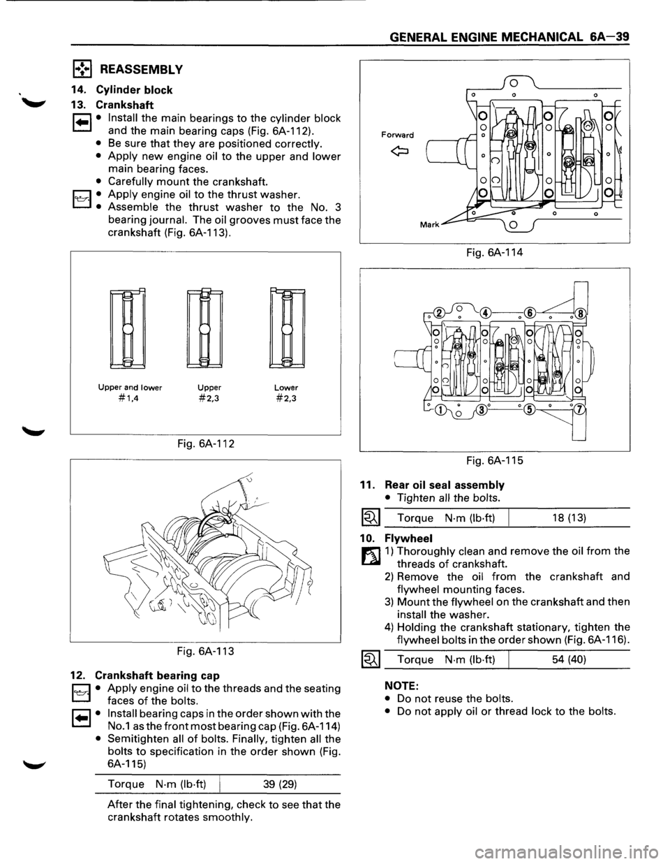
1,.!.,1 REASSEMBLY
14. Cylinder block
13. Crankshaft
1•1• Install the main bearings to the cylinder block
and the main bearing caps (Fig. 6A-112).
• Be sure that they are positioned correctly.
•
Apply new engine oil to the upper and lower
main bearing faces.
• Carefully mount the crankshaft.
1~·1 .• Apply engine oil to the thrust washer.
Assemble the thrust washer to the No. 3
bearing
journal. The oil grooves must face the
crankshaft (Fig. 6A-113).
r--!::"
11-1
~
Upper and lower
#1,4
Upper
#2,3
Fig. 6A-112
Fig. 6A-113
12. Crankshaft bearing cap
Lower
#2,3
D • Apply engine oil to the threads and the seating
L:J faces of the bolts.
I• I• Install bearing caps in the order shown with the
No.1 as the front most bearing cap (Fig. 6A-114)
• Semitighten all of bolts. Finally, tighten all the
bolts to specification in the order shown (Fig.
6A-115)
Torque
N·m (lb·ft) 39 (29)
After the final tightening, check to see that the
crankshaft rotates
smoothly.
GENERAL ENGINE MECHANICAL &A-39
Forward
Fig. 6A-114
Fig. 6A-115
11. Rear oil seal assembly
• Tighten all the bolts.
~~~ Torque N·m (lb·ft)
1 0. Flywheel
18 (13)
r:l]1) Thoroughly clean and remove the oil from the
threads
of crankshaft.
2) Remove the oil from the crankshaft and
flywheel mounting faces.
3) Mount the flywheel on the crankshaft and then
install the washer.
4) Holding the crankshaft stationary, tighten the
flywheel bolts in the order shown (Fig. 6A-116).
~~~ Torque N·m (lb·ft) 54 (40)
NOTE:
•
Do not reuse the bolts.
•
Do not apply oil or thread lock to the bolts.
Page 608 of 1928
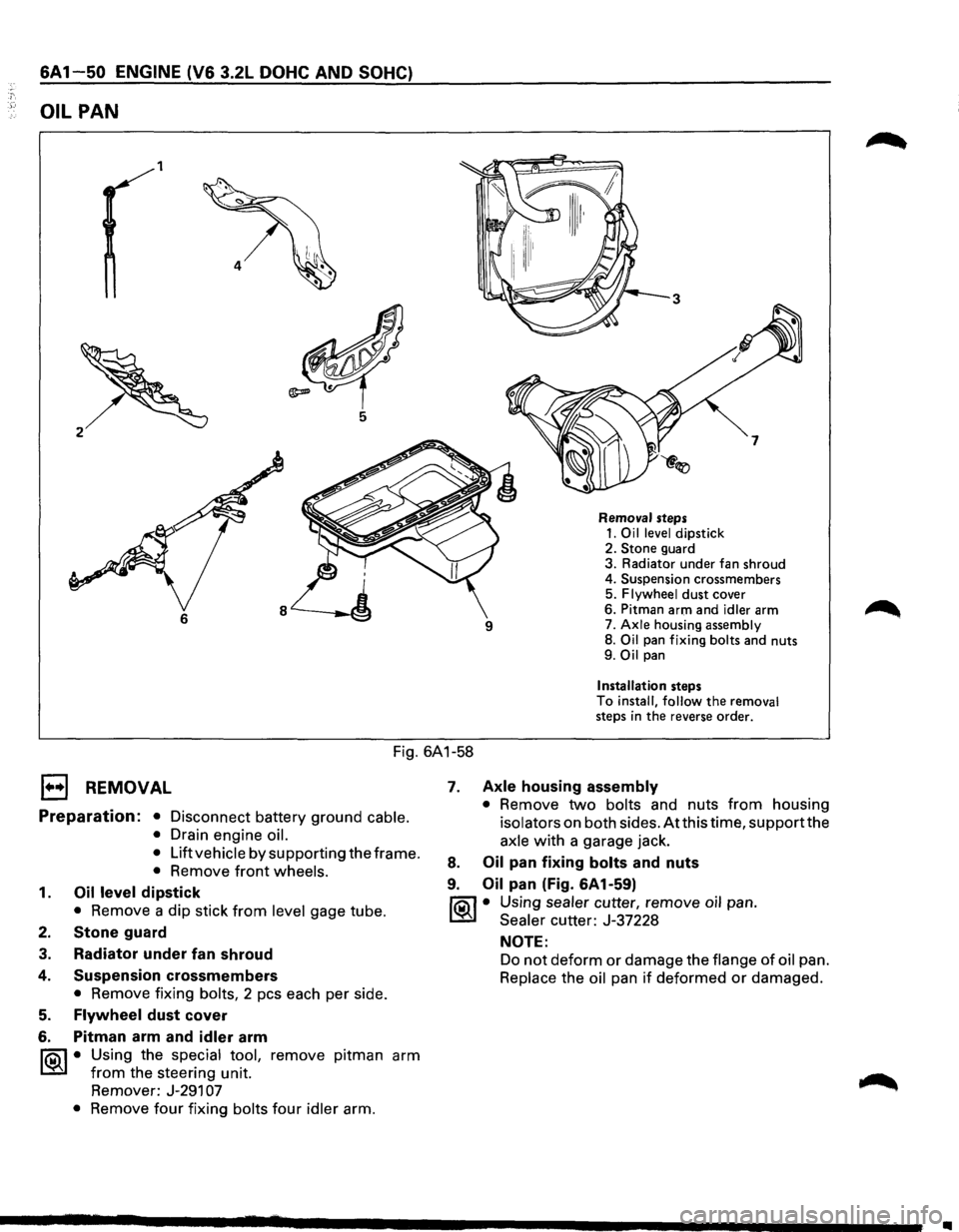
6A1 50 ENGINE (V6 3.2L DOHC AND SOHC)
OIL PAN
1
6
Removal steps 1. Oil level dipstick
2. Stone guard
3. Radiator under fan shroud
4. Suspension crossmembers
5.
Flywheel dust cover
6. Pitman arm and
idler arm
7. Axle housing assembly 8. Oil pan fixing bolts and nuts
9. Oil pan
Installation steps
To install, follow the removal steps in the reverse order.
Fig. 6A1-58
1••1 REMOVAL
Preparation: • Disconnect battery ground cable.
•
Drain engine oil.
•
Lift vehicle by supporting the frame.
• Remove front wheels.
1. Oil level dipstick
• Remove a dip stick from level gage tube.
2. Stone guard
3. Radiator under fan shroud
4.
5.
6.
Suspension crossmembers
• Remove fixing bolts, 2 pes each per side.
Flywheel dust cover
Pitman arm and
idler arm
~·
Using the special tool, remove pitman arm
from the steering unit.
Remover: J-291
07
• Remove four fixing bolts four idler arm.
7. Axle housing assembly
• Remove two bolts and nuts from housing
isolators on both sides. Atthis time, supportthe
axle with a garage jack.
8. Oil pan fixing bolts and nuts
9. Oil pan (Fig. 6A1-59)
fiOil • Using sealer cutter, remove oil pan.
~ Sealer cutter: J-37228
NOTE:
Do not deform or damage the flange of oil pan.
Replace the oil pan if deformed or damaged.
•
Page 609 of 1928
.., ¢'
-
Fig. 6A1-59
1••1 INSTALLATION
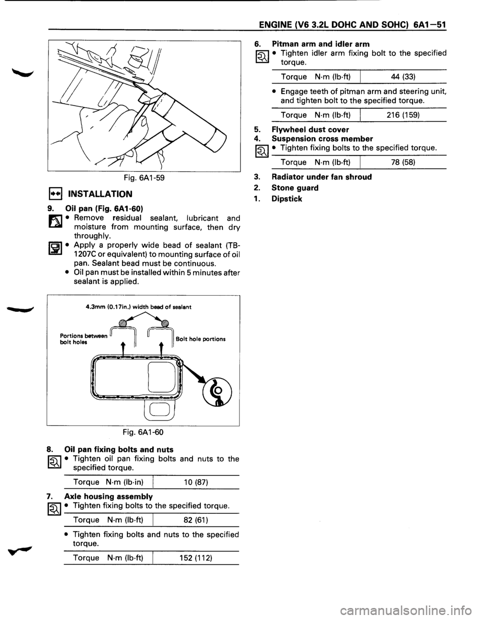
9. Oil pan (Fig. 6A1-60)
m • Remove residual sealant, lubricant and
~ moisture from mounting surface, then dry
throughly.
ISPI• Apply a properly wide bead of sealant (TB-
1207C or equivalent) to mounting surface of oil
pan. Sealant bead must be continuous.
• Oil pan must be installed within 5 minutes after
sealant is applied.
4.3mm (0.17in.) width bead of sealant
Portions between bolt holes
Fig. 6A1-60
8. Oil pan fixing bolts and nuts
Bolt hole portions
~ • Tighten oil pan fixing bolts and nuts to the
~ specified torque.
Torque
N·m (lb·in)
10 (87)
7. Axle housing assembly
~~~· Tighten fixing bolts to the specified torque.
Torque
N·m (lb·ft) 82 (61)
• Tighten fixing bolts and nuts to the specified
torque.
Torque
N·m (lb·ft) 152 (112)
ENGINE (V6 3.2L DOHC AND SOHC) 6A 1-51
6. Pitman arm and idler arm
~·
Tighten idler arm fixing bolt to the specified
torque.
Torque
N·m (lb·ft) 44 (33)
• Engage teeth of pitman arm and steering unit,
and tighten
bolt to the specified torque.
Torque
N·m (lb·ft) 216 (159)
5. Flywheel dust cover
4. Suspension cross member
~~~ • Tighten fixing bolts to the specified torque.
Torque
N·m (lb·ft) I 78 (58)
3. Radiator under fan shroud
2. Stone guard
1. Dipstick
Page 616 of 1928
,): .. • T·
6A 1-58 ENGINE (V6 3.2L DOHC AND SOHC)
EJ REMOVAL
1. Engine assembly
• See "Engine Assembly
Removal and Instal-
lation".
2. Crankshaft pulley
3. Timing belt cover
4. Timing belt
5. Oil pan
6. Oil pipe and rubber ring
7. Oil strainer and rubber ring
8. Oil pump assembly
9. Crankcase side bolts
10.
Oil gallery
11. Flywheel
12.
Rear oil seal retainers
13.
Connecting rod caps
14.
Crankshaft main bearing caps
15.
Crankshaft and main bearings
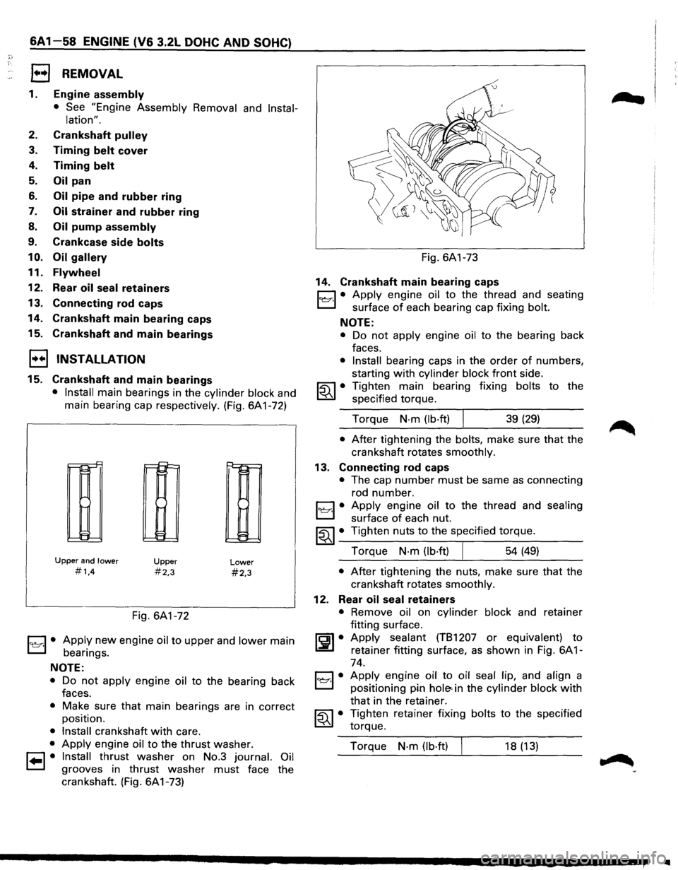
1•+1 INSTALLATION
15. Crankshaft and main bearings
• Install main bearings in the cylinder block and
main bearing cap respectively. (Fig. 6A1-72)
r-r-'
II-
!:=
Upper and lower
#1,4
~
!::
E:
Upper
#2,3
Fig. 6A1-72
Lower
#2,3
1~1· Apply new engine oil to upper and lower main
bearings.
NOTE:
• Do not apply engine oil to the bearing back
faces.
• Make sure that main bearings are in correct
position.
• Install crankshaft with care.
• Apply engine oil to the thrust washer.
1•1• Install thrust washer on No.3 journal. Oil
grooves in thrust washer must face the
crankshaft. (Fig. 6A1-73) Fig.
6A1-73
14. Crankshaft main bearing caps
C1 • Apply engine oil to the thread and seating
L:::J surface of each bearing cap fixing bolt.
NOTE:
• Do not apply engine oil to the bearing back
faces.
• Install bearing caps in the order of numbers,
starting
with cylinder block front side.
~~~ • Tighten main bearing fixing bolts to the
specified torque.
Torque
N·m (lb·ft) I 39 (29)
• After tightening the bolts, make sure that the
crankshaft rotates
smoothly.
13. Connecting rod caps
• The cap number must be same as connecting
rod number.
1~1· Apply engine oil to the thread and sealing
surface of each nut.
~~~· Tighten nuts to the specified torque.
Torque
N·m (lb·ft) 54 (49)
• After tightening the nuts, make sure that the
crankshaft rotates
smoothly.
12. Rear oil seal retainers
• Remove oil on cylinder block and retainer
fitting surface.
~~~· Apply sealant (TB1207 or equivalent) to
retainer fitting surface, as shown in Fig. 6A 1-
74.
C1 • Apply engine oil to oil seal lip, and align a
El positioning pin hole< in the cylinder block with
that in the retainer.
~~~· Tighten retainer fixing bolts to the specified
torque.
Torque
N·m (lb·ft) 18 (13)
IIIII
Page 617 of 1928
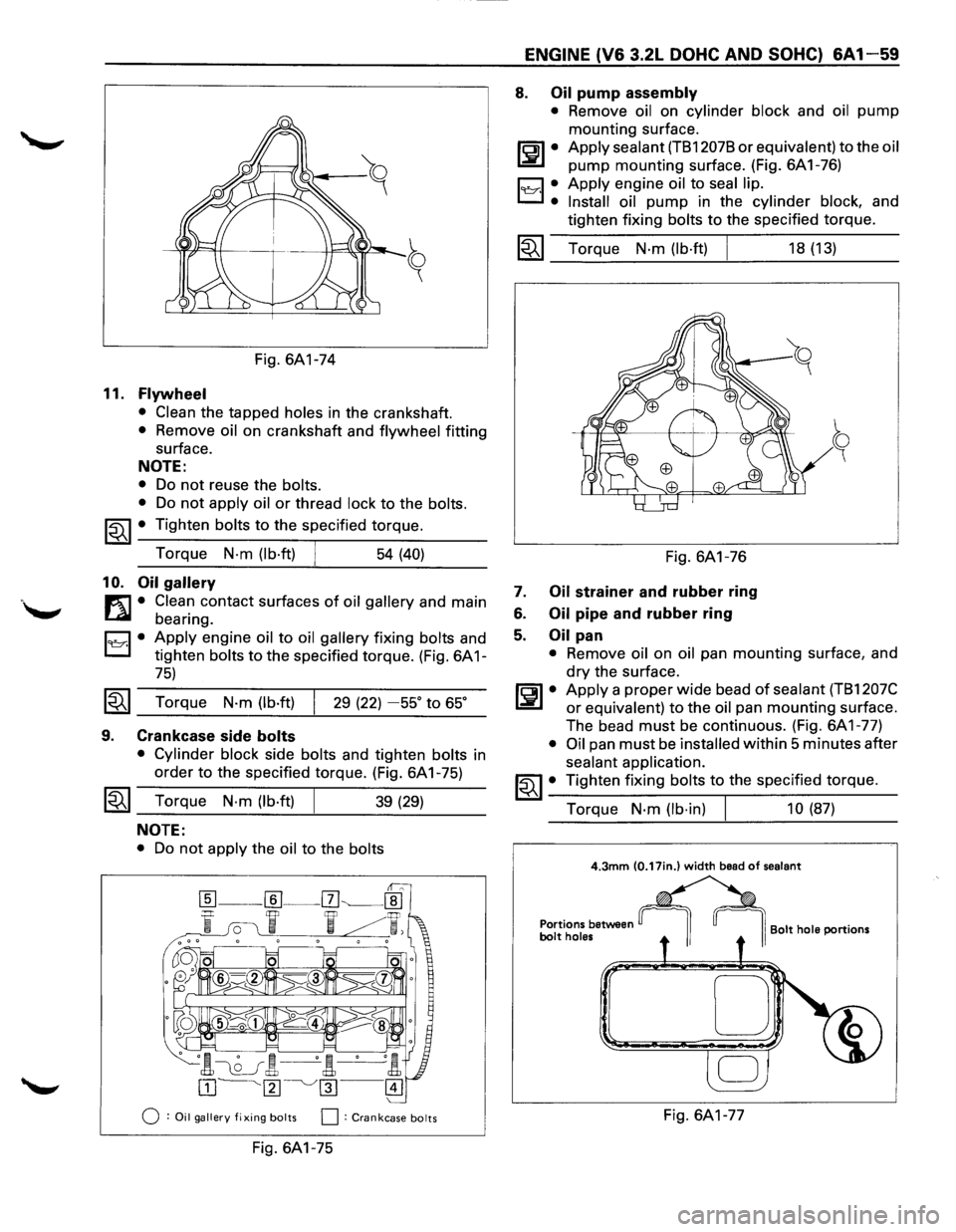
Fig. 6A1-74
11. Flywheel
• Clean the tapped holes in the crankshaft.
• Remove oil on crankshaft and flywheel fitting
surface.
NOTE:
• Do not reuse the bolts.
•
Do not apply oil or thread lock to the bolts.
~~~ • Tighten bolts to the specified torque.
Torque
N-m (lb·ft) 54 (40)
10. Oil gallery
m • Clean contact surfaces of oil gallery and main
~ bearing.
D • Apply engine oil to oil gallery fixing bolts and
L:::J tighten bolts to the specified torque. (Fig. 6A 1-
75)
~~~ Torque N·m (lb·ft) 29 (22) -55° to 65°
9. Crankcase side bolts
• Cylinder block side bolts and tighten bolts in
order
to the specified torque. (Fig. 6A 1-75)
~~~ Torque N·m (lb·ft) 39 (29)
NOTE:
• Do not apply the oil to the bolts
0 :Oil gallery fixing bolts 0: Crankcase bolts
Fig. 6A1-75
ENGINE (V6 3.2L DOHC AND SOHC) 6A1-59
8. Oil pump assembly
• Remove oil on cylinder block and oil pump
mounting surface.
ll:JI• Apply sealant (TB12078 or equivalent) to the oil
pump mounting surface. (Fig. 6A1-76)
19Y·I •. Apply engine oil to seal lip.
Install oil
pump in the cylinder block, and
tighten fixing
bolts to the specified torque.
1~1 Torque N·m (lb·ft)
Fig. 6A1-76
7. Oil strainer and rubber ring
6. Oil pipe and rubber ring
5. Oil pan
18 (13)
• Remove oil on oil pan mounting surface, and
dry the surface.
~~~· Apply a proper wide bead of sealant (TB1207C
or equivalent) to the oil pan mounting surface.
The bead
must be continuous. (Fig. 6A1-77)
• Oil pan must be installed within 5 minutes after
sealant application.
~~~· Tighten fixing bolts to the specified torque.
Torque
N·m (lb·in) 10 (87)
4.3mm (0.17in.) width bead of sealant
Portions between bolt holes I Bolt hole portions
D
Fig. 6A1-77
Page 618 of 1928
6A1-60 ENGINE (V6 3.2L DOHC AND SOHC}
4. Timing belt
• See "Timing Belt Removal and Installation".
3. Timing belt cover
2. Crankshaft pulley
~ • Using special tool J-8614-01, hold the
~ crankshaft pulley.
~~~· Tighten center bolt to the specified torque.
Torque
N·m (lb·ft) 167 (123)
1. Engine assembly
• See "Engine Assembly Removal and Instal
lation".
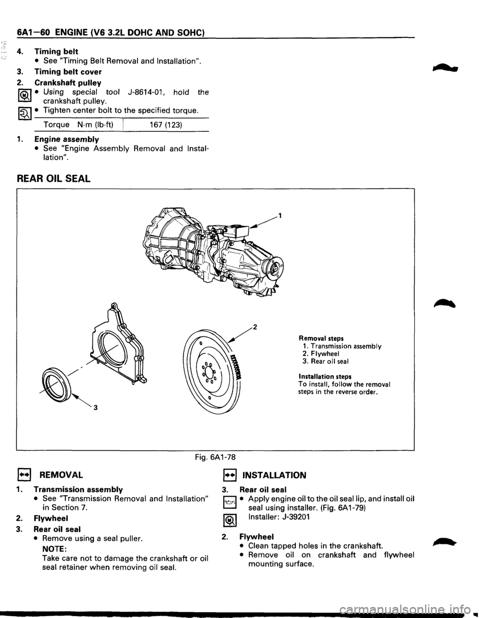
REAR OIL SEAL
Removal steps
1. Transmission assembly
2.
Flywheel 3. Rear oil seal
Installation steps To install, follow the removal
steps in the reverse order.
Fig. 6A1-78
E) REMOVAL
1. Transmission assembly
• See "Transmission Removal and Installation"
in Section 7.
2. Flywheel
3. Rear oil seal
•
Remove using a seal puller.
NOTE:
Take care
not to damage the crankshaft or oil
seal retainer
when removing oil seal.
1••1 INSTALLATION
3. Rear oil seal
C1 • Apply engine oil to the oil seal lip, and install oil
L:::l seal using installer. (Fig. 6A 1-79)
1®1 Installer: J-39201
2. Flywheel
• Clean tapped holes in the crankshaft.
• Remove oil on crankshaft and flywheel
mounting surface.
...