wheel ISUZU TROOPER 1995 Workshop Manual
[x] Cancel search | Manufacturer: ISUZU, Model Year: 1995, Model line: TROOPER, Model: ISUZU TROOPER 1995Pages: 1928
Page 1056 of 1928
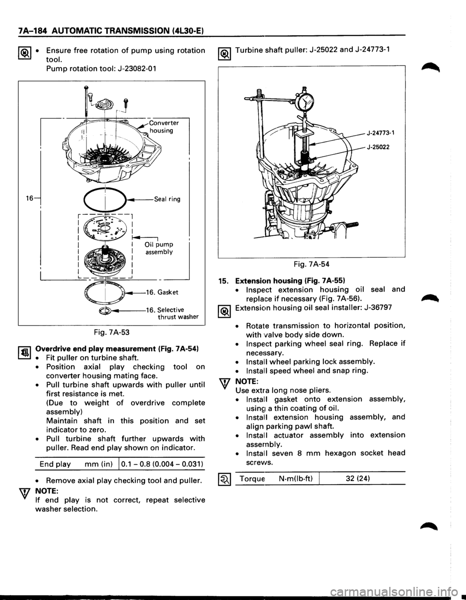
7A-184 AUTOMATIC TRANSMISSION (4L30-E)
~· Ensure free rotation of pump using rotation
tool.
16
Pump rotation tool: J-23082-01
-----16. Selective thrust washer
Fig. 7A-53
l'fil Overdrive end play measurement (Fig. 7A-54)
~ • Fit puller on turbine shaft.
• Position axial play checking tool on
converter housing mating face.
• Pull turbine shaft upwards with puller until
first resistance is met.
(Due
to weight of overdrive complete
assembly)
Maintain shaft in this position and set
indicator to zero.
• Pull turbine shaft further upwards with
puller. Read end play shown on indicator.
End
play mm (in) I 0.1 -0.8 (0.004-0.031)
1®.1 Turbine shaft puller: J-25022 and J-24773-1
J-24773·1
J-25022
Fig. 7A-54
15. Extension housing (Fig. 7A-55)
• Inspect extension housing oil seal and
replace if necessary (Fig. 7 A-56).
1®.1 Extension housing oil seal installer: J-36797
• Rotate transmission to horizontal position,
with valve body side down.
• Inspect parking wheel seal ring. Replace if
necessary.
• Install wheel parking lock assembly.
• Install
speed wheel and snap ring.
NOTE:
Use extra long nose pliers.
• Install
gasket onto extension assembly,
usin£1 a thin coating of oil.
• Install
extension housing assembly, and
align parking pawl shaft.
• Install actuator assembly into extension
assembly.
• Install
seven 8 mm hexagon socket head
screws.
• Remove axial play checking tool and puller. ~~~ Torque N-m(lb.ft) 32 (24) W NOTE: _ __:_ ___ __:___:__J_ _ __.::..:::....=_:..:.__ __
If end play is not correct, repeat selective
washer selection.
Page 1057 of 1928
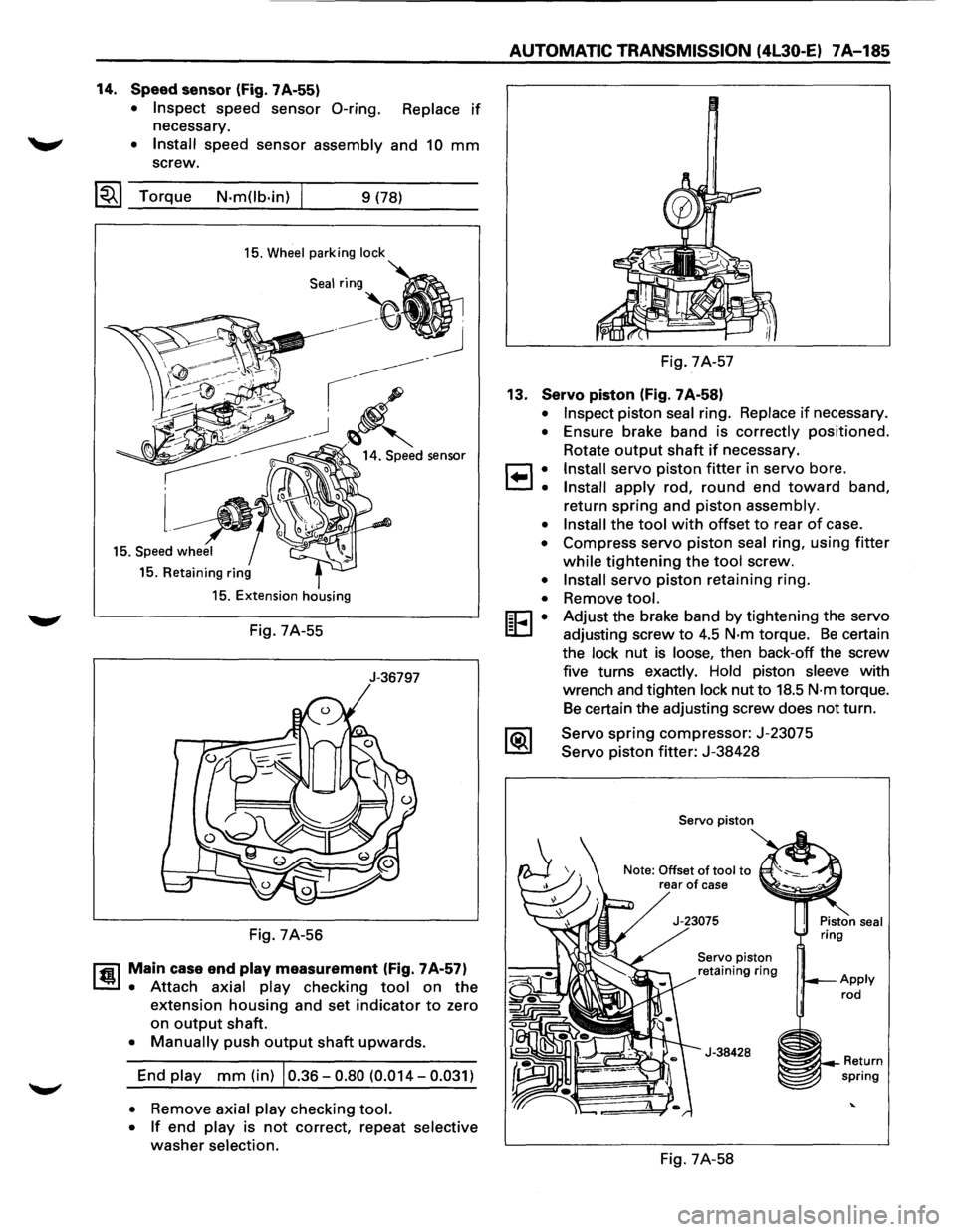
14. Speed sensor (Fig. 7A-55)
• Inspect speed sensor 0-ring. Replace if
necessary.
~ • Install speed sensor assembly and 10 mm
screw.
~~~ Torque N-m(lb-in) 9 (78)
15. Wheel parking lock
15. Retaining ring
15. Extension housing
Fig. 7A-55
J-36797
Fig. 7A-56
rfil Main case end play measurement (Fig. 7A-57)
~ • Attach axial play checking tool on the
extension housing and set indicator to zero
on
output shaft.
• Manually push output shaft upwards.
End play mm (in) 10.36-0.80 (0.014-0.031)
• Remove axial play checking tool.
• If end play is not correct, repeat selective
washer selection.
AUTOMATIC TRANSMISSION (4l30-E) 7A-185
Fig. 7A-57
13. Servo piston (Fig. 7A-58)
•
•
8:
•
•
•
•
[E•
Inspect piston seal ring. Replace if necessary .
Ensure brake band is correctly
positioned .
Rotate
output shaft if necessary.
Install servo piston fitter in servo bore.
Install apply rod, round end toward band,
return
spring and piston assembly.
Install the tool with offset to rear of case .
Compress servo
piston seal ring, using fitter
while tightening the tool screw.
Install servo piston retaining ring .
Remove
tool.
Adjust the brake band by tightening the servo
adjusting screw
to 4.5 N-m torque. Be certain
the lock nut
is loose, then back-off the screw
five turns exactly. Hold piston sleeve with
wrench and tighten lock nut to
18.5 N-m torque.
Be certain the adjusting screw does not turn.
Servo
spring compressor: J-23075
Servo piston fitter: J-38428
Servo piston
Note: Offset
of tool to rear of case
Servo piston
retaining ring
J-38428
Fig. 7A-58
~~--Return spring
Page 1090 of 1928
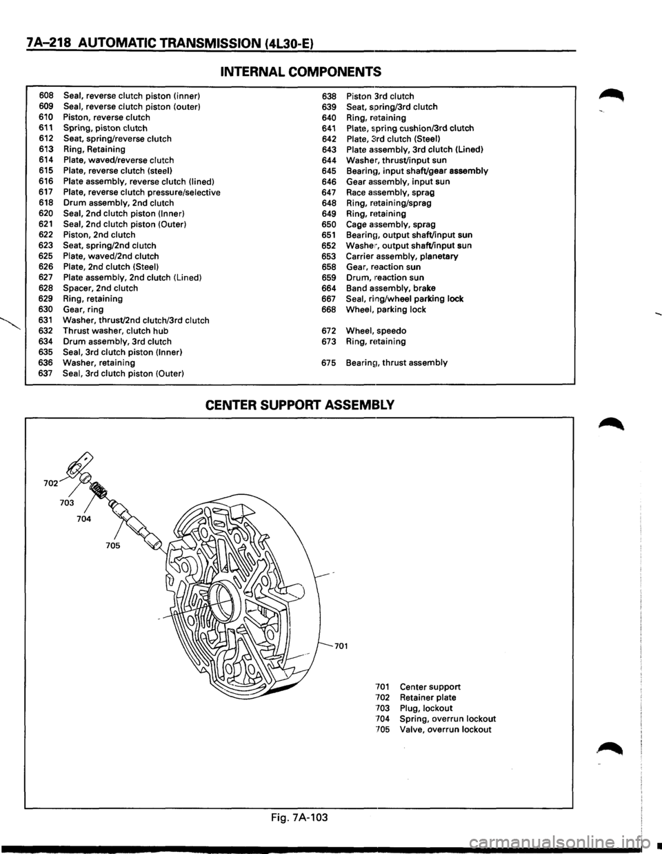
7A-218 AUTOMATIC TRANSMISSION (4L30-E}
608 Seal, reverse clutch piston (inner)
609 Seal, reverse clutch piston (outer)
610 Piston, reverse clutch 611 Spring, piston clutch 612 Seat, spring/reverse clutch 613 Ring, Retaining
614
Plate, waved/reverse clutch 615 Plate, reverse clutch (steel) 616 Plate assembly, reverse clutch (lined)
617 Plate, reverse clutch pressure/selective
618 Drum assembly, 2nd clutch
620 Seal, 2nd clutch piston (Inner) 621 Seal, 2nd clutch piston (Outer) 622 Piston, 2nd clutch
623 Seat, spring/2nd clutch 625 Plate, waved/2nd clutch 626 Plate, 2nd clutch (Steel)
627 Plate assembly, 2nd clutch (Lined)
628 Spacer, 2nd clutch 629 Ring, retaining
630 Gear, ring 631 Washer, thrust/2nd clutch/3rd clutch 632 Thrust washer, clutch hub
634 Drum assembly, 3rd clutch
635 Seal, 3rd clutch piston (Inner) 636 Washer, retaining
637 Seal, 3rd clutch piston (Outer)
INTERNAL COMPONENTS
638 Piston 3rd clutch 639 Seat, spring/3rd clutch
640 Ring, n~taining 641 Plate, spring cushion/3rd clutch 642 Plate, :::rd clutch (Steel) 643 Plate assembly, 3rd clutch (Lined)
644 Washer,
thrust/input sun
645 Bearino, input shaft/gear assembly 646 Gear assembly, input sun
647
Race assembly, sprag
648 Ring, mtaining/sprag
649 Ring,
mtaining 650 Cage a:;sembly, sprag 651 Bearinn, output shaft/input sun
652 Washer, output shaft/input sun
653 Carrier assembly, planetary 658 Gear, reaction sun
659 Drum, 1·eaction sun
664 Band
assembly, brake 667 Seal, ring/wheel parking lock 668 Wheel, parking lock
672 Wheel, speedo
673 Ring, rEttaining
675
Bearin~1. thrust assembly
CENTER SUPPORT ASSEMBLY
701
Fig. 7A-103
701 Center support 702 Retainer plate
703 Plug, lockout
704 Spring,
overrun lockout
705 Valve,
overrun lockout
•
Page 1093 of 1928
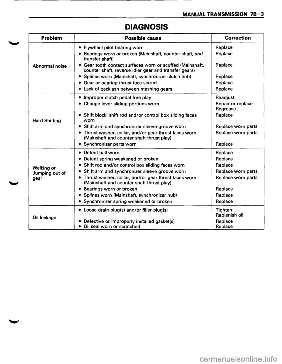
MANUAL TRANSMISSION 78-3
DIAGNOSIS
Problem Possible cause Correction
•
Flywheel pilot bearing worn Replace
•
Bearings worn or broken (Mainshaft, counter shaft, and Replace
transfer shaft)
Abnormal noise • Gear tooth contact surfaces worn or scuffed (Mainshaft, Replace
counter shaft, reverse idler gear and transfer gears)
• Splines worn (Mainshaft, synchronizer clutch hub) Replace
•
Gear or bearing thrust face seized Replace
•
Lack of backlash between meshing gears Replace
• Improper clutch pedal
free play Readjust
• Change lever sliding portions worn Repair or replace
Regrease
• Shift block, shift rod and/or control box sliding faces Replace
Hard Shifting worn
• Shift arm and synchronizer sleeve groove worn Replace worn parts
• Thrust washer, collar, and/or gear thrust faces worn Replace worn parts
(Mainshaft and counter shaft thrust
play)
•
Synchronizer parts worn Replace
•
Detent ball worn Replace
•
Detent spring weakened or broken Replace
Walking
or • Shift rod and/or control box sliding faces worn Replace
Jumping out of • Shift arm and synchronizer sleeve groove worn Replace worn parts
gear
• Thrust washer, collar, and/or gear thrust faces worn Replace worn parts
(Mainshaft and counter shaft thrust
play)
•
Bearings worn or broken Replace
• Splines
worn (Mainshaft, synchronizer hub) Replace
•
Synchronizer spring weakened or broken Replace
•
Loose drain plug(s) and/or filler plug(s) Tighten
Oil leakage Replenish
oil
• Defective or improperly installed gasket(s) Replace
• Oil seal
worn or scratched Replace
Page 1094 of 1928
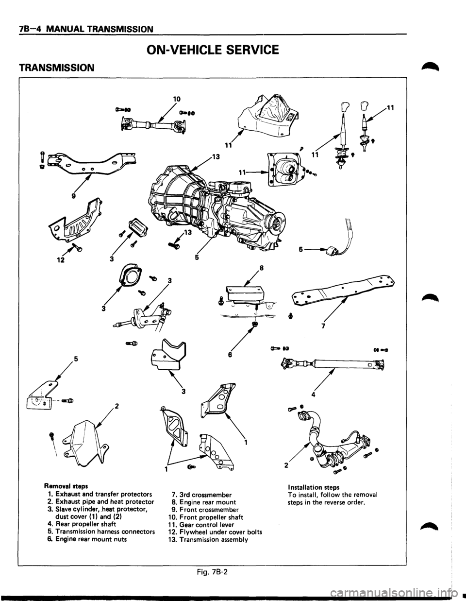
78-4 MANUAL TRANSMISSION
ON-VEHICLE SERVICE
TRANSMISSION
10
~··
v
"
9
r 12 5
3
5
3
2
1
Removal steps
1. Exhaust and transfer protectors
7. 3rd crossmember
2. Exhaust pipe and heat protector 8. Engine rear mount 3. Slave cylinder, .heat protector,
9. Front crossmember dust cover ( 1) and (2) 10. Front propeller shaft
4. Rear propeller shaft
11. Gear control lever 5. Transmission harness connectors
12. Flywheel under cover bolts 6. Engine rear mount nuts
13. Transmission assembly
Fig. 78-2
(a
11
t
.__J
7
[J
4
Installation steps To install,
follow the removal steps in the reverse order.
•
Page 1096 of 1928
78-6 MANUAL TRANSMISSION
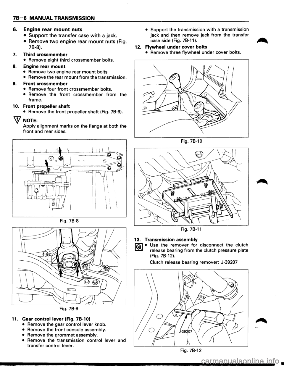
6. Engine rear mount nuts
• Support the transfer case with a jack.
• Remove two engine rear mount nuts (Fig.
78-8).
7. Third crossmember
• Remove eight third crossmember bolts.
8. Engine rear mount
• Remove two engine rear mount bolts.
•
Remove the rear mount from the transmission.
9. Front crossmember
• Remove four front crossmember bolts.
•
Remove the front crossmember from the
frame.
10. Front propeller shaft
• Remove the front propeller shaft (Fig. 78-9).
W NOTE:
Apply alignment marks on the flange at both the
front and rear sides.
I I I
II
Fig. 78-8
Fig. 78-9
11. Gear control lever (Fig. 78-1 0)
• Remove the gear control lever knob.
• Remove the front console assembly.
•
Remove the grommet assembly.
•
Remove the transmission control lever and
transfer
control lever. •
Support
the transmission with a transmission
jack
.and then remove jack from the transfer
case side (Fig. 78-11).
~
12. Flywheel under cover bolts
• Remove three flywheel under cover bolts.
Fig. 78-10
Fig. 78-11
13. Transmission assembly
li5\l • Use the remover for disconnect the clutch
~ release bearing from the clutch pressure plate
(Fig. '78-12).
Clutch release
bearing remover: J-39207
Fig. 78-12
•
Page 1099 of 1928
12. Flywheel under cover bolts
• Install
three flywheel under cover bolts.
11. Gear control lever
• Install
the transmission control lever and
transfer
control lever.
• Install
the grommet assembly.
• Install
the front console assembly.
• Install
the gear control lever knob.
• Support the transfer case with a jack and then
remove the transmission jack
from
transmission side.
10. Front propeller shaft
• Install the front propeller shaft.
~~~ Torque N·m (lb·ft) 63 (46)
9. Front crossmember
• Install the front crossmember.
~~~ Torque N·m (lb·ft) 78 (58)
8. Engine rear mount
• Install the engine rear mount.
~~~ Torque N·m (lb·ft) 41 (30)
7. 3rd crossmember
• Install the 3rd crossmember.
1~1 Torque N-m (lb·ft) 50 (37)
6. Engine rear mount nuts
~~~ Torque N-m (lb·ft) 50 (37)
• Remove the transmission jack.
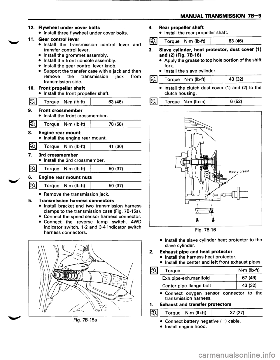
5. Transmission harness connectors
• Install bracket and two transmission harness
clamps to the transmission case (Fig. 78-15a).
• Connect the speed sensor harness connector.
• Connect the reverse lamp switch, 4WD
indicator
switch, 1-2 and 3-4 indicator switch
harness connectors.
Fig. 78-15a
MANUAL TRANSMISSION 78-9
4. Rear propeller shaft
• Install the rear propeller shaft.
I~I __ T_o_rq~u_e __ N_·m~(_lb_·ft~)~ _____ 6_3~(_46~) ____ _
3. Slave cylinder. heat protector. dust cover (1)
and (2) (Fig. 78-16)
• Apply the grease to top hole portion of the shift
fork.
• Install the slave cylinder.
~~~ Torque N·m (lb·ft) I 43 (32) _..:....__~----
• Install the clutch dust cover (1) and (2) to the
clutch housing.
~~~ Torque N·m (lb·in) 6 (52)
Apply grease
Fig. 78-16
• Install the slave cylinder heat protector to the
slave cylinder.
2. Exhaust pipe and heat protector
• Install the harness heat protector.
• Install the center and left front exhaust pipes.
~~~ Torque
Exh.pipe-exh.manifold
Center pipe
flange bolt N·m
(lb·ft)
67 (49)
43 (32)
• Connect oxygen sensor connector to the
transmission harness.
1. Exhaust and transfer protectors
~~~ Torque N·m (lb·ft) 37 (27)
• Connect battery negative (-) cable.
• Install
engine hood.
Page 1129 of 1928
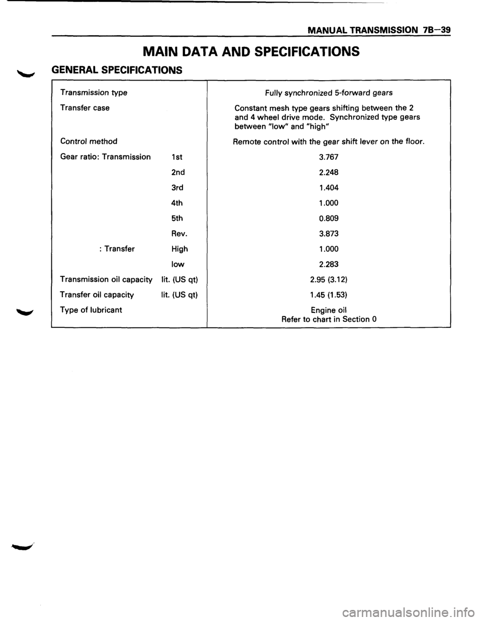
MANUAL TRANSMISSION 78-39
MAIN DATA AND SPECIFICATIONS
GENERAL SPECIFICATIONS
Transmission type
Transfer case
Control method
Gear ratio: Transmission
1st
2nd
3rd
4th
5th
Rev.
:Transfer High
low
Transmission oil capacity lit. (US qt)
Transfer
oil capacity lit. (US qt)
Type
of lubricant Fully
synchronized
5-forward gears
Constant mesh type gears shifting between the
2
and 4 wheel drive mode. Synchronized type gears
between
"low" and "high"
Remote control with the gear shift lever on the floor.
3.767
2.248
1.404
1.000
0.809
3.873
1.000
2.283
2.95
(3.12)
1.45 (1.53)
Engine oil
Refer to chart in Section 0
Page 1139 of 1928
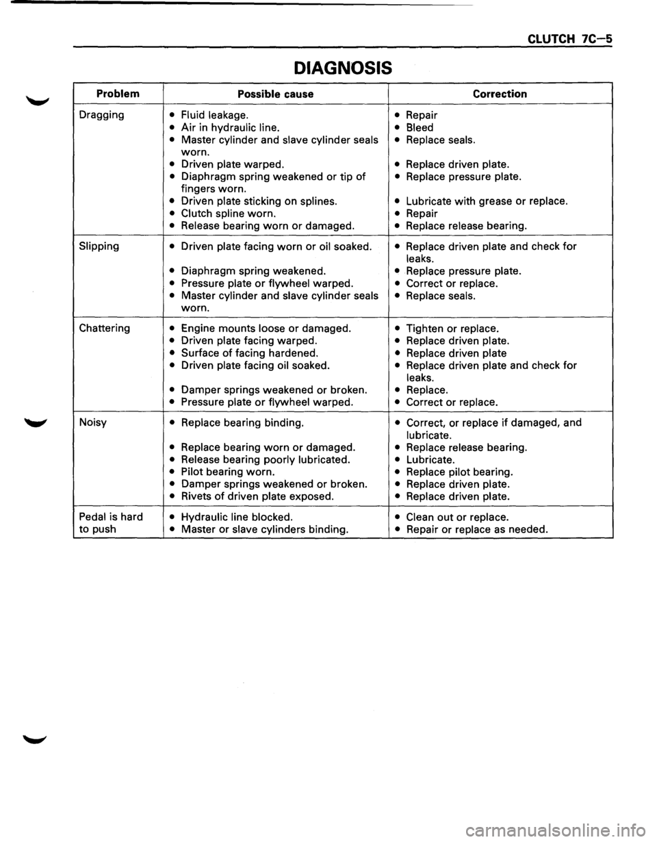
CLUTCH 7C-5
DIAGNOSIS
Problem Possible cause Correction
Dragging • Fluid leakage.
• Repair
• Air in hydraulic line.
• Bleed
•
Master cylinder and slave cylinder seals • Replace seals.
worn.
• Driven plate warped. • Replace driven plate.
•
Diaphragm spring weakened or tip of • Replace pressure plate.
fingers worn.
• Driven plate sticking on splines. • Lubricate with grease or replace.
• Clutch spline
worn. • Repair
• Release bearing worn or damaged. • Replace release bearing.
Slipping
• Driven plate facing worn or oil soaked. • Replace driven plate and check for
leaks.
•
Diaphragm spring weakened. • Replace pressure plate.
•
Pressure plate or flywheel warped. • Correct or replace.
•
Master cylinder and slave cylinder seals
• Replace seals.
worn.
Chattering
• Engine mounts loose or damaged. • Tighten or replace.
•
Driven plate facing warped. • Replace driven plate.
•
Surface of facing hardened. • Replace driven plate
•
Driven plate facing oil soaked. • Replace driven plate and check for
leaks.
•
Damper springs weakened or broken. • Replace.
•
Pressure plate or flywheel warped. • Correct or replace.
Noisy • Replace bearing binding. • Correct, or replace if damaged, and
lubricate.
• Replace
bearing worn or damaged. • Replace release bearing.
• Release bearing poorly lubricated.
• Lubricate.
• Pilot bearing worn. • Replace pilot bearing.
• Damper springs weakened or broken. • Replace driven plate.
•
Rivets of driven plate exposed. • Replace driven plate.
Pedal
is hard • Hydraulic line blocked.
• Clean out or replace.
to push • Master or slave cylinders binding. • Repair or replace as needed.
Page 1140 of 1928
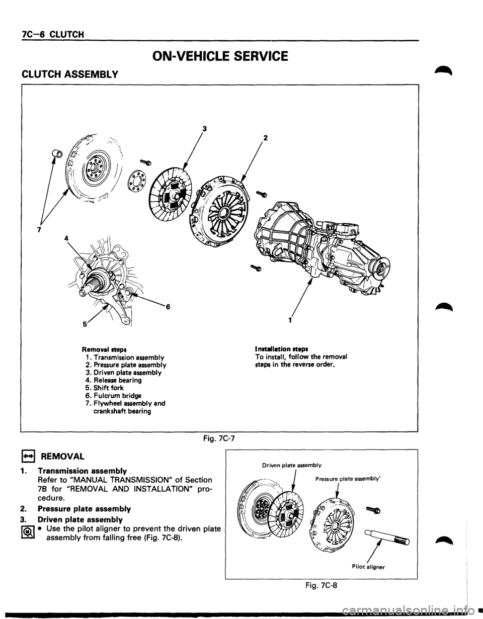
7C-6 CLUTCH
ON-VEHICLE SERVICE
CLUTCH ASSEMBL V
6
Removal steps
1••1 REMOVAL
1. Transmission assembly
2. Pressure plate assembly
3. Driven plate assembly 4. Release bearing 5. Shift fork
6. Fulcrum bridge
7. Flywheel assembly and
crankshaft bearing
1. Transmission assembly
3
Fig. 7C-7
Refer to "MANUAL TRANSMISSION" of Section
78
for "REMOVAL AND INSTALLATION" pro
cedure.
2. Pressure plate assembly
3. Driven plate assembly
li0\1 • Use the pilot aligner to prevent the driven plate
lSi~ assembly from falling free (Fig. 7C-8).
2
Installation steps
To install,
follow the removal steps in the reverse order.
Drivtm plate assembly
Pressure plate assembly'
Pilot aligner
Fig. 7C-8
•