wheel ISUZU TROOPER 1995 Workshop Manual
[x] Cancel search | Manufacturer: ISUZU, Model Year: 1995, Model line: TROOPER, Model: ISUZU TROOPER 1995Pages: 1928
Page 632 of 1928
68 - 4 ENGINE COOLING
ON-VEHICLE SERVICE
DRAINING AND REFILLING COOLING
SYSTEM
Before draining the cooling system, inspect the sys
tem and perform any necessary service to ensure that
it is clean, does not leak and is in proper working
order. The Engine Coolant (EC) level should be be
tween the "MIN" and "MAX" lines of reserve tank
when the engine is cold. If low, check for leakage and
add
EC up to the "MAX" line. There should not be any
excessive deposit of rust or scales around the radiator
cap
or radiator filler hole, and the EC should also be
free
from oil. Replace the EC if excessively dirty.
1. Completely drain the cooling system by opening
the drain petcock at the bottom of the radiator.
2. Remove the radiator cap.
W WARNING
To avoid the danger of being burned, do not
remove the cap while the engine and radiator
are still hot. Scalding fluid and steam can be
blown out under pressure.
3. Disconnect all hoses from the EC reserve tank.
Scrub and clean the inside of the reserve tank with
soap and water. Flush it well with clean water,
then drain it. Install the reserve tank and hoses.
WATER PUMP
3
j
2
4. Refill the cooling system with the EC using a
solution that is at least 50 percent antifreeze but no
more than 70 percent antifreeze.
5. Fill the radiator to the base of the filler neck.
Fill the EC reserve tank to "MAX" line when the
engine is cold.
6. Block the drive wheels and firmly apply the park
ing brake.
Shift an automatic transmission to "P"
(Park) or a manual transmission to neutral.
7. Remove the radiator cap. Start the engine and
warm it up at 2,500 -3,000 rpm for about 30
minutes.
8. When the air comes out from the radiator filler
neck and the EC level has gone down, replenish
with the EC. Repeat this procedure until the EC
level does not go down. Then stop the engine and
install the radiator cap. Let the engine cool down.
9. After the engine has cooled, replenish with EC up
to the "MAX" line of the reserve tank.
10. Start the engine. With the engine running at 3,000
rpm, make sure there is no running water sound
from the heater core (behind the center console).
11. If the running water sound is heard, repeat steps 7
to 10.
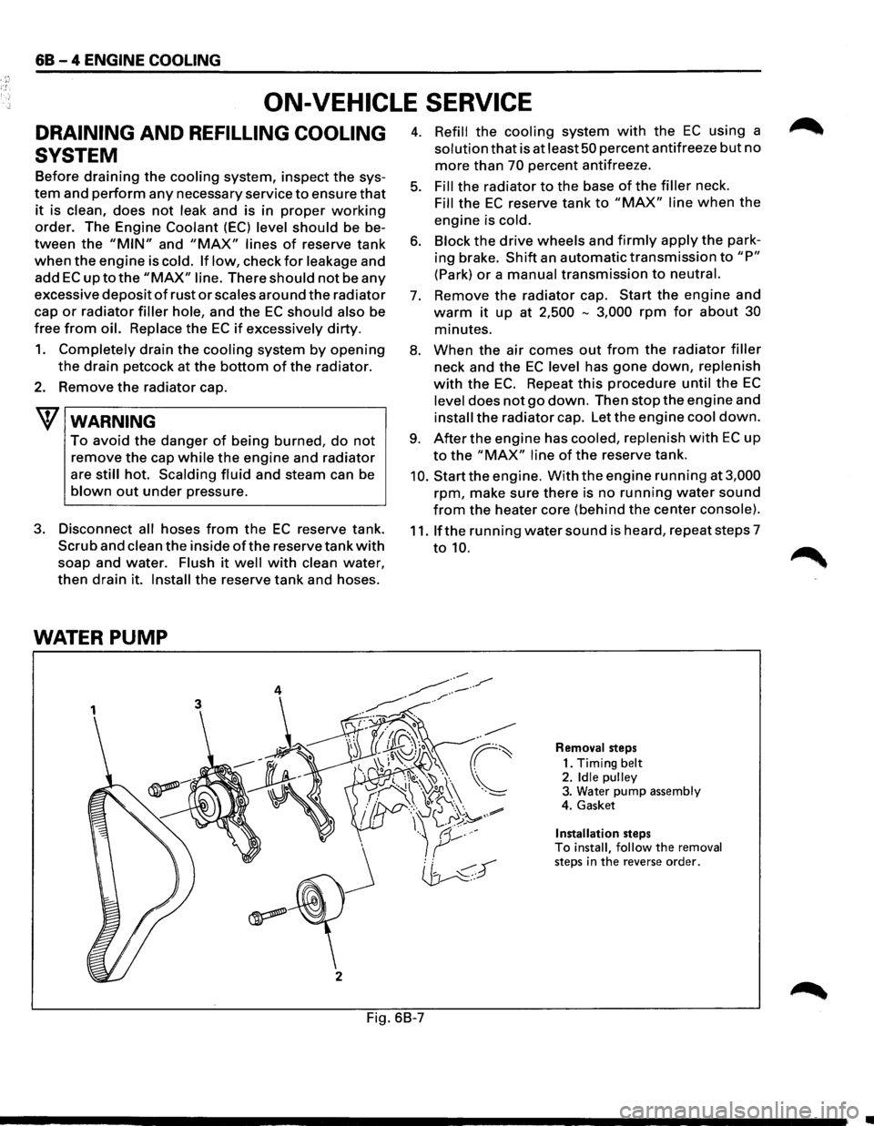
Removal steps
1. Timing
belt 2. Idle pulley 3. Water pump assembly
4. Gasket
Installation steps To install, follow the removal steps in the reverse order.
Fig. 6B-7
•
Page 648 of 1928
6C-6 ENGINE FUEL
FUEL TANK
7
1 3
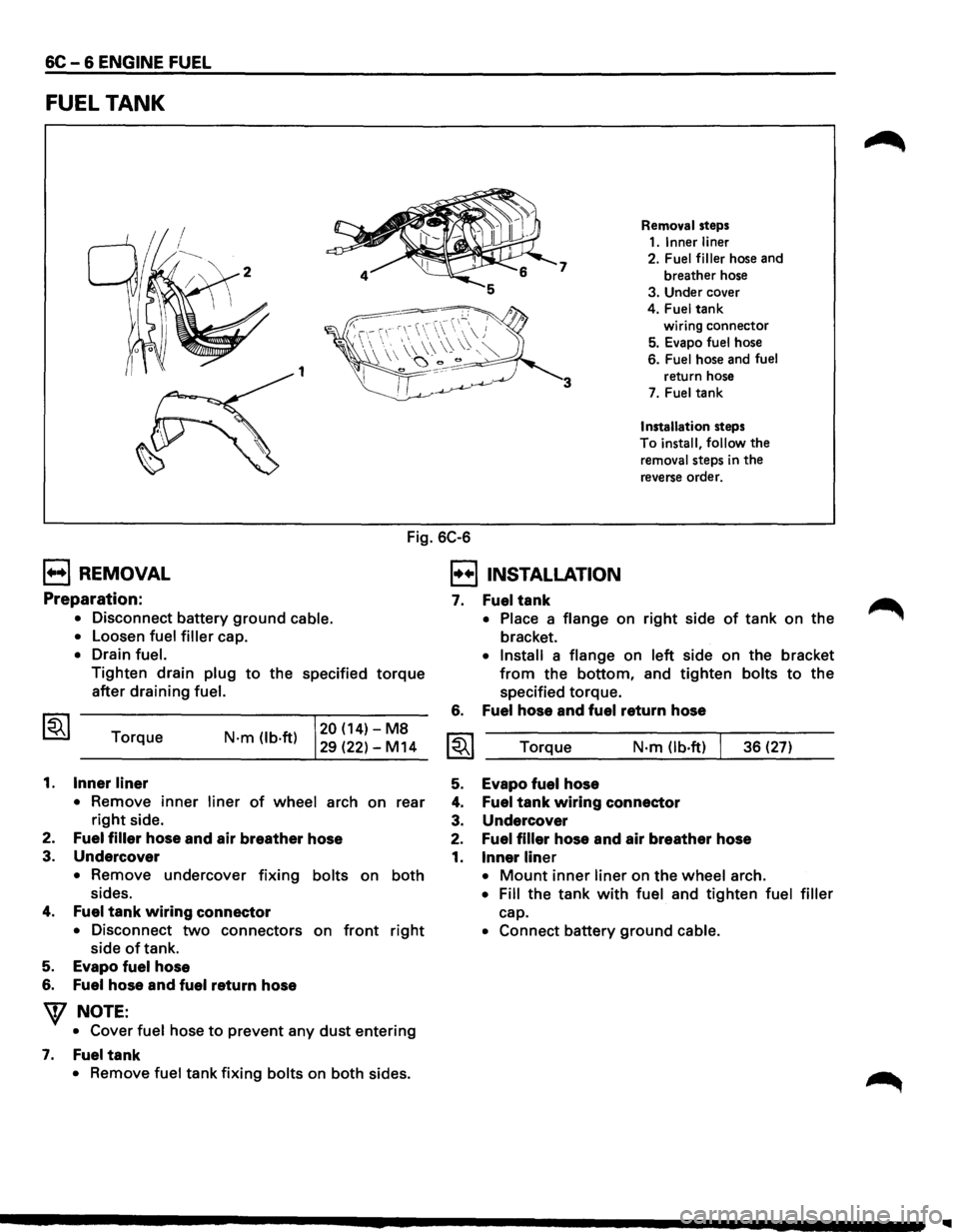
Removal steps
1.1nnerliner
2. Fuel filler hose and
breather hose
3. Under cover
4.
Fuel tank
wiring connector
5. Evapo fuel hose
6.
Fuel hose and fuel
return hose
7. Fuel tank
Installation steps
To
install, follow the
removal steps in the
reverse order.
Fig. 6C-6
B REMOVAL
Preparation:
• Disconnect battery ground cable.
•
Loosen fuel filler cap.
• Drain fuel.
Tighten drain plug to the specified torque
after draining fuel.
Torque
1. Inner liner
N·m (lb·ft) 20 (14)-M8
29 (22)-M14
• Remove
inner liner of wheel arch on rear
right side.
2.
Fuel filler hose and air breather hose
3.
Undercover
• Remove undercover fixing bolts on both
sides.
4. Fuel tank wiring connector
• Disconnect two connectors on front right
side of tank.
5. Evapo fuel hose
6. Fuel hose and fuel return hose
W NOTE:
• Cover fuel hose to prevent any dust entering
7. Fuel tank
• Remove fuel tank fixing bolts on both sides.
I!!] INSTALLATION
7.
6.
Fuel tank
• Place a flange on right side of tank on the
bracket.
• Install a flange on left side on the bracket
from the bottom, and tighten bolts to the
specified torque.
Fuel hose and fuel return hose
Torque N·m Ob·ft) 36 (27)
5. Evapo fuel hose
4. Fuel tank wiring connector
3. Undercover
2. Fuel filler hose and air breather hose
1. Inner liner
• Mount inner liner on the wheel arch.
• Fill the tank with fuel and tighten fuel filler
cap.
• Connect battery ground cable.
Page 698 of 1928
6E2-2 DRIVEABILITY AND EMISSIONS
DRIVEABILITV AND EMISSIONS GENERAL INFORMATION
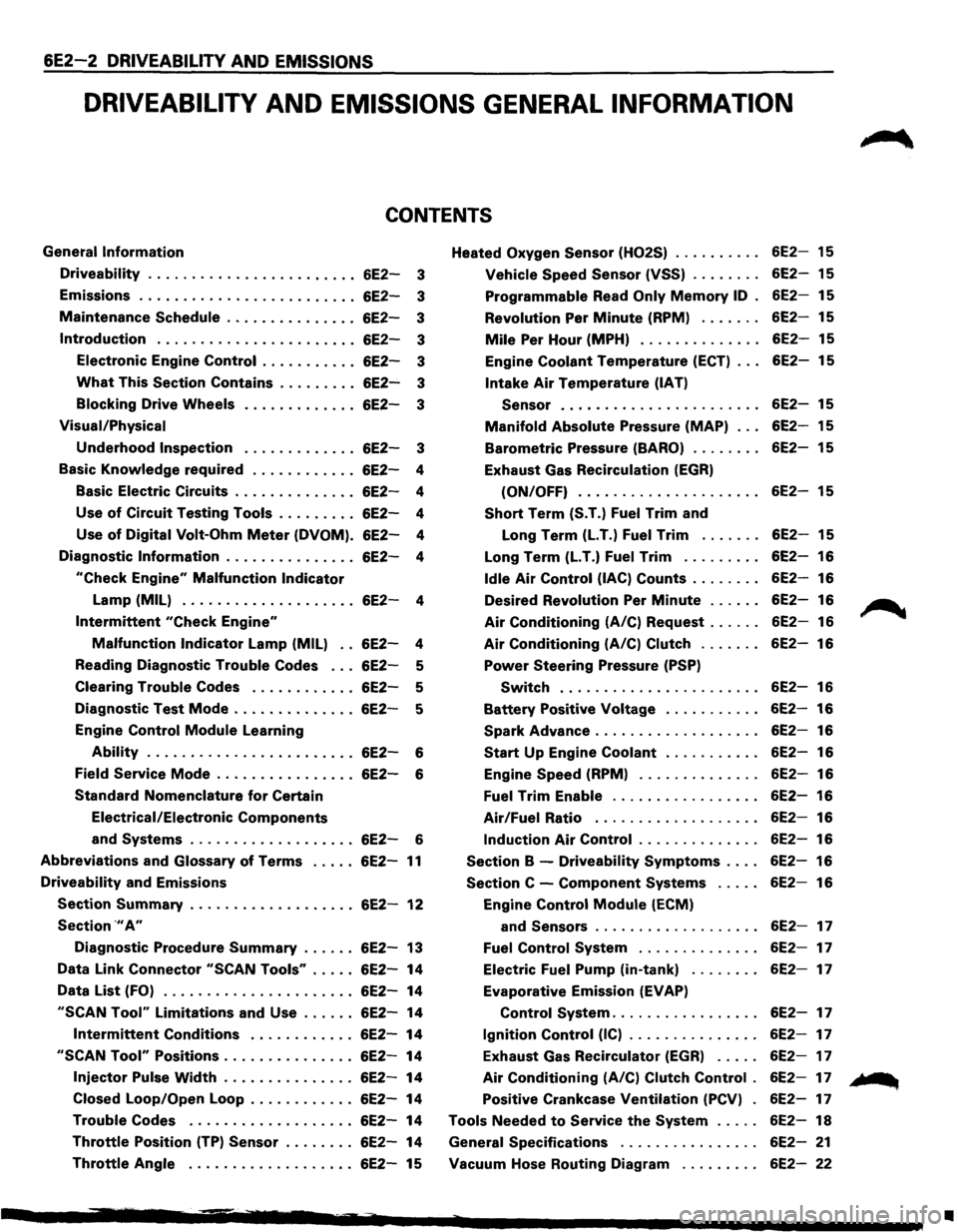
CONTENTS
General Information
Driveability ....................... .
Emissions
........................ .
Maintenance
Schedule .............. .
Introduction ...................... .
Electronic Engine
Control .......... .
What This Section Contains ........ .
Blocking Drive Wheels
Visual/Physical
Underhood Inspection
6E2-3
6E2-3
6E2-3
6E2-3
6E2-3
6E2-3
6E2-3
6E2-3
Basic
Knowledge required . . . . . . . . . . . . 6E2-4
Basic Electric Circuits . . . . . . . . . . . . . .
6E2-4
Use
of Circuit Testing Tools . . . . . . . . . 6E2-4
Use
of Digital Volt-Ohm Meter (DVOM). 6E2-4
Diagnostic
Information . . . . . . . . . . . . . . . 6E2-4
"Check Engine" Malfunction Indicator
Lamp (MIL) . . . . . . . . . . . . . . . . . . . . 6E2-4
Intermittent "Check Engine"
Malfunction Indicator Lamp (MIL) . . 6E2-4
Reading Diagnostic
Trouble Codes . . . 6E2-5
Clearing
Trouble Codes . . . . . . . . . . . . 6E2-5
Diagnostic Test
Mode .............. 6E2-5
Engine Control
Module Learning
Ability . . . . . . . . . . . . . . . . . . . . . . . . 6E2-6
Field
Service Mode . . . . . . . . . . . . . . . . 6E2-6
Standard Nomenclature
for Certain
Electrical/Electronic
Components
and Systems . . . . . . . . . . . . . . . . . . . 6E2-6
Abbreviations and Glossary of Terms ..... 6E2-11
Driveability and Emissions
Section Summary ................... 6E2-12
Section .,. A"
Diagnostic Procedure Summary ...... 6E2-13
Data Link Connector
"SCAN Tools" ..... 6E2-14
Data
List (FO) ...................... 6E2-14
"SCAN Tool" Limitations and Use ...... 6E2-14
Intermittent Conditions ............ 6E2-14
"SCAN Tool" Positions ............... 6E2-14
Injector Pulse Width ............... 6E2-14
Closed Loop/Open Loop . . . . . . . . . . . .
6E2-14
Trouble Codes ................... 6E2-14
Throttle Position (TP) Sensor . . . . . . . . 6E2-14
Throttle Angle . . . . . . . . . . . . . . . . . . . 6E2-15 Heated
Oxygen
Sensor (H02S)
Vehicle Speed Sensor (VSS) ....... .
Programmable Read Only Memory ID .
Revolution
Per Minute (RPM) ...... .
Mile Per Hour (MPH) ............. .
Engine
Coolant Temperature (ECT) .. .
Intake Air Temperature (IAT)
Sensor
...................... .
Manifold Absolute Pressure (MAP) .. .
Barometric Pressure (BARO) ....... .
Exhaust Gas Recirculation
(EGR)
(ON/OFF) .................... .
Short Term (S.T.) Fuel Trim and
Long Term
(LT.) Fuel Trim ...... .
Long Term
(LT.) Fuel Trim ........ .
Idle Air Control (lAC) Counts ....... .
Desired Revolution
Per Minute ..... .
Air Conditioning (A/C) Request ..... .
Air Conditioning (A/C) Clutch ...... .
Power Steering Pressure (PSP)
Switch ...................... .
Battery Positive Voltage .......... .
Spark Advance .................. .
Start Up Engine Coolant .......... .
Engine
Speed (RPM) ............. .
Fuel Trim Enable ................ .
Air/Fuel Ratio .................. .
Induction Air Control ............. .
Section B -Driveability Symptoms ... .
Section C -Component Systems .... .
Engine
Control Module (ECM)
and
Sensors .................. .
Fuel Control System ............. .
Electric
Fuel Pump (in-tank) ....... .
Evaporative Emission
(EVAP)
Control System ................ .
Ignition Control (IC) .............. .
Exhaust Gas Recirculator
(EGR) .... .
Air Conditioning (A/C) Clutch Control .
Positive Crankcase Ventilation (PCV) .
Tools Needed
to Service the System .... .
General Specifications
............... .
Vacuum Hose Routing Diagram
........ .
6E2-15
6E2-15
6E2-15
6E2-15
6E2-15
6E2-15
6E2-15
6E2-15
6E2-15
6E2-15
6E2-15
6E2-16
6E2-16
6E2-16
6E2-16
6E2-16
6E2-16
6E2-16
6E2-16
6E2-16
6E2-16
6E2-16
6E2-16
6E2-16
6E2-16
6E2-16
6E2-17
6E2-17
6E2-17
6E2-17
6E2-17
6E2-17
6E2-17
6E2-17
6E2-18
6E2-21
6E2-22
~
... ...
•
Page 699 of 1928
---
DRIVEABILITV AND EMISSIONS 6E2-3
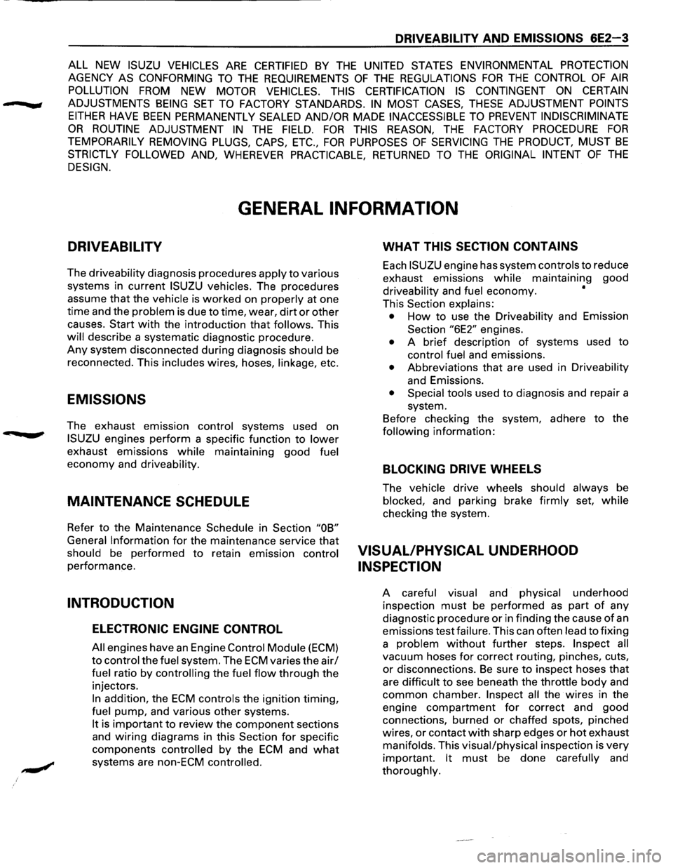
ALL NEW ISUZU VEHICLES ARE CERTIFIED BY THE UNITED STATES ENVIRONMENTAL PROTECTION
AGENCY AS CONFORMING TO THE REQUIREMENTS OF THE REGULATIONS FOR THE CONTROL OF AIR
POLLUTION FROM NEW MOTOR VEHICLES. THIS CERTIFICATION IS CONTINGENT ON CERTAIN
ADJUSTMENTS BEING SET TO FACTORY STANDARDS. IN MOST CASES, THESE ADJUSTMENT POINTS
EITHER HAVE BEEN PERMANENTLY SEALED AND/OR MADE INACCESSIBLE TO PREVENT INDISCRIMINATE
OR ROUTINE ADJUSTMENT IN THE FIELD. FOR THIS REASON, THE FACTORY PROCEDURE FOR
TEMPORARILY REMOVING PLUGS, CAPS, ETC., FOR PURPOSES OF SERVICING THE PRODUCT, MUST BE
STRICTLY FOLLOWED AND, WHEREVER PRACTICABLE, RETURNED TO THE ORIGINAL INTENT OF THE
DESIGN.
GENERAL INFORMATION
DRIVEABILITY
The driveability diagnosis procedures apply to various
systems in current
ISUZU vehicles. The procedures
assume
that the vehicle is worked on properly at one
time and the
problem is due to time, wear, dirt or other
causes.
Start with the introduction that follows. This
will describe a systematic diagnostic procedure.
Any system disconnected during diagnosis should be
reconnected. This
includes wires, hoses, linkage, etc.
EMISSIONS
The exhaust emission control systems used on
ISUZU engines perform a specific function to lower
exhaust emissions while maintaining good fuel
economy and driveability.
MAINTENANCE SCHEDULE
Refer to the Maintenance Schedule in Section "OB"
General Information for the maintenance service that
should be performed to retain emission control
performance.
INTRODUCTION
ELECTRONIC ENGINE CONTROL
All engines have an Engine Control Module (ECM)
to control the fuel system. The ECM varies the air/
fuel ratio by controlling the fuel flow through the
injectors.
In addition, the ECM controls the ignition timing,
fuel pump, and various other systems.
It is important to review the component sections
and
wiring diagrams in this Section for specific
components
controlled by the ECM and what
systems are non-ECM controlled.
WHAT THIS SECTION CONTAINS
Each ISUZU engine has system controls to reduce
exhaust emissions
while maintaining good
driveability and fuel economy. •
This Section explains:
•
How to use the Driveability and Emission
Section
"6E2" engines.
• A brief description of systems used to
control fuel and emissions.
• Abbreviations that are used in Driveability
and Emissions.
• Special tools used to diagnosis and repair a
system.
Before checking the
system, adhere to the
following information:
BLOCKING DRIVE WHEELS
The vehicle drive wheels should always be
blocked, and parking brake firmly set, while
checking the system.
VISUAL/PHYSICAL UNDERHOOD
INSPECTION
A careful visual and physical underhood
inspection must
be performed as part of any
diagnostic procedure
or in finding the cause of an
emissions test failure. This can often lead to fixing
a
problem without further steps. Inspect all
vacuum hoses for correct routing, pinches, cuts,
or disconnections. Be sure to inspect hoses that
are
difficult to see beneath the throttle body and
common chamber.
Inspect all the wires in the
engine
compartment for correct and good
connections, burned or chaffed spots, pinched
wires, or contact with sharp edges or hot exhaust
manifolds. This visual/physical inspection is very
important. It must be done carefully and
thoroughly.
Page 719 of 1928
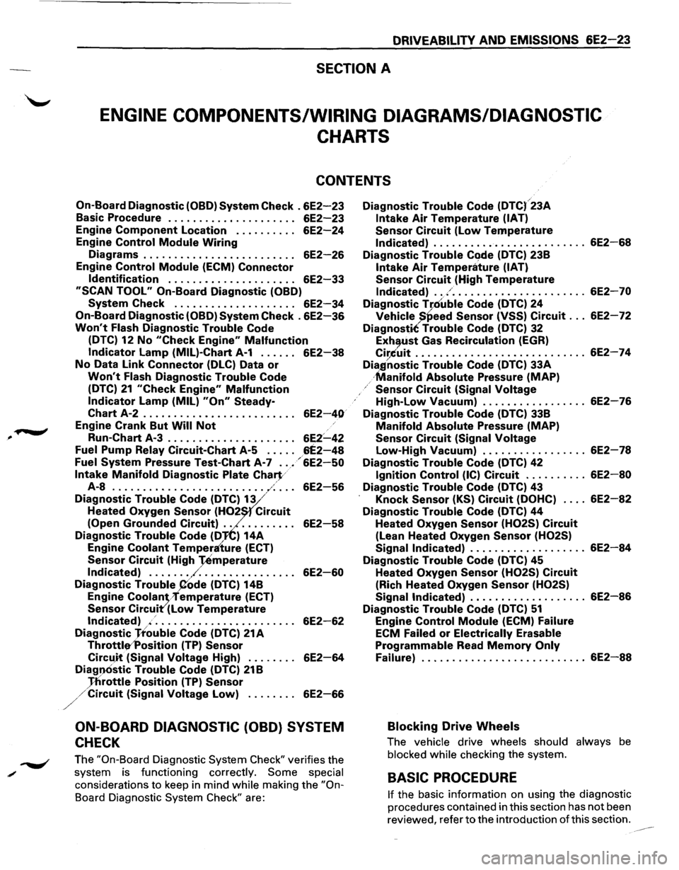
DRIVEABILITY AND EMISSIONS 6E2-23
SECTION A
ENGINE COMPONENTS/WIRING DIAGRAMS/DIAGNOSTIC
CHARTS
CONTENTS
On-Board Diagnostic (OBD} System Check . 6E2-23
Basic Procedure . . . . . . . . . . . . . . . . . . . . . 6E2-23
Engine Component Location . . . . . . . . . . 6E2-24
Engine Control Module Wiring
Diagrams . . . . . . . . . . . . . . . . . . . . . . . . . 6E2-26
Engine Control Module (ECM) Connector
Identification . . . . . . . . . . . . . . . . . . . . . 6E2-33
"SCAN TOOL" On-Board Diagnostic (OBD)
System Check . . . . . . . . . . . . . . . . . . . . 6E2-34
On-Board Diagnostic (OBD} System Check . 6E2-36
Won't Flash Diagnostic Trouble Code
(DTC)
12 No "Check Engine" Malfunction
Indicator Lamp (MIL)-Chart A-1 . . . . . . 6E2-38
No Data Link Connector (DLC) Data or
Won't Flash Diagnostic Trouble Code
(DTC)
21 "Check Engine" Malfunction
Indicator Lamp (MIL} "On" Steady-
Chart A-2 . . . . . . . . . . . . . . . . . . . . . . . . . 6E2-40
Engine Crank But Will Not
Run-Chart A-3 . . . . . . . . . . . . . . . . . . . . . 6E2:.....42
Fuel Pump Relay Circuit-Chart A-5 . . . . . 6E2-48
Fuel System Pressure Test-Chart A-7 ..• /6E2-50
Intake Manifold Diagnostic Plate Chart/
A-8 ......................... ,-:· . . . 6E2-56
Diagnostic Trouble Code (DTC~13 /
Heated Oxygen Sensor (H02 Circuit
(Open Grounded Circuit) . . . . . . . . . . . 6E2-58
Diagnostic Trouble Code (D'JiC) 14A
Engine Coolant Temperaiure (ECT}
Sensor Circuit (High -:remperature
Indicated) ....... /. . . . . . . . . . . . . . . . 6E2-60
Diagnostic Trouble P'ode (DTC} 14B
Engine
Coolan·vremperature (ECT)
Sensor Circuit'(Low Temperature
Indicated) ./. . . . . . . . . . . . . . . . . . . . . . . 6E2-62
Diagnostic Jtouble Code (DTC) 21A
Throtti~,.Position (TP) Sensor
Circu)t (Signal Voltage High) . . . . . . . . 6E2-64
Diag.,Ostic Trouble Code (DTC) 21B
Jflrottle Position (TP} Sensor
//Circuit (Signal Voltage Low} ........ 6E2-66
ON-BOARD DIAGNOSTIC (OBD) SYSTEM
CHECK
The "On-Board Diagnostic System Check" verifies the
system is functioning correctly.
Some special
considerations
to keep in mind while making the "On
Board Diagnostic System Check" are:
Diagnostic Trouble Code (DTC(23A
Intake Air Temperature (IAT)
Sensor Circuit (low Temperature
Indicated) ......................... 6E2-68
Diagnostic Trouble Code (DTC) 23B
Intake Air Temperature (IAT)
Sensor Circuit (High Temperature
Indicated) ... / ...................... 6E2-70
Diagnostic T[ouble Code (DTC} 24
Vehicle )!Peed Sensor (VSS} Circuit ... 6E2-72
DiagnostiC Trouble Code (DTC) 32
Exh,tist Gas Recirculation (EGR}
Cir,.Cuit ............................ 6E2-74
Dia,gnostic Trouble Code (DTC} 33A
·Manifold Absolute Pressure (MAP)
Sensor Circuit (Signal Voltage
High-Low Vacuum) ................. 6E2-76
Diagnostic Trouble Code (DTC) 33B
Manifold Absolute Pressure (MAP}
Sensor Circuit (Signal Voltage
Low-High Vacuum) ................. 6E2-78
Diagnostic Trouble Code (DTC) 42
Ignition Control (IC) Circuit . . . . . . . . . . 6E2-80
Diagnostic Trouble Code (DTC} 43
Knock Sensor (KS} Circuit (DOHC) .... 6E2-82
Diagnostic Trouble Code (DTC) 44
Heated Oxygen Sensor (H02S} Circuit
(Lean Heated Oxygen Sensor (H02S)
Signal Indicated} . . . . . . . . . . . . . . . . . . . 6E2-84
Diagnostic Trouble Code (DTC) 45
Heated Oxygen Sensor (H02S) Circuit
(Rich Heated Oxygen Sensor (H02S)
Signal Indicated) . . . . . . . . . . . . . . . . . . . 6E2-86
Diagnostic Trouble Code (DTC) 51
Engine Control Module (ECM} Failure
ECM Failed
or Electrically Erasable
Programmable Read Memory Only
Failure} ........................... 6E2-88
Blocking Drive Wheels
The vehicle drive wheels should always be
blocked
while checking the system.
BASIC PROCEDURE
If the basic information on using the diagnostic
procedures contained in this section has
not been
reviewed, refer
to the introduction of this section.
Page 729 of 1928
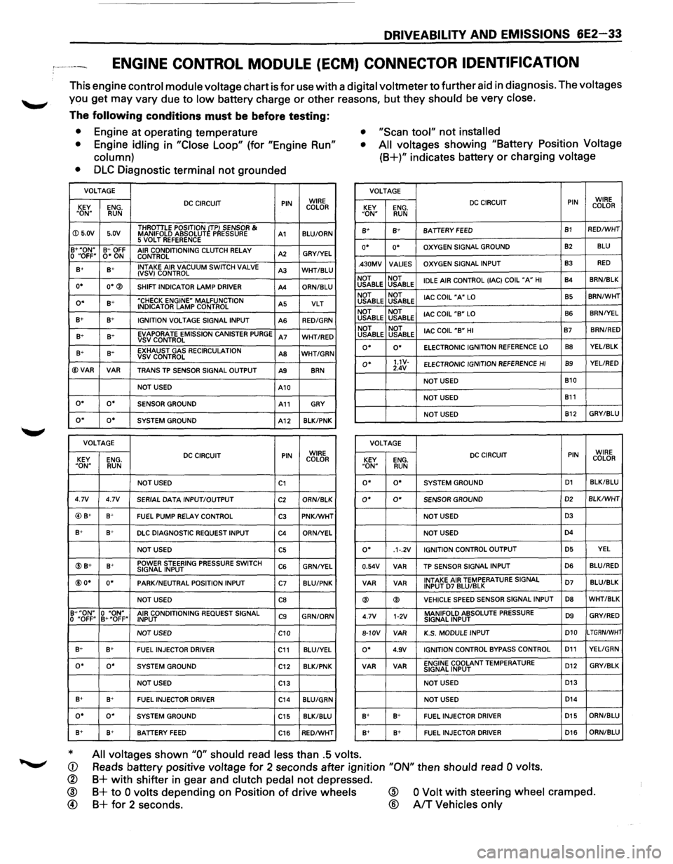
DRIVEABILITY AND EMISSIONS 6E2-33
ENGINE CONTROL MODULE (ECM) CONNECTOR IDENTIFICATION
This engine control module voltage chart is for use with a digital voltmeter to further aid in diagnosis. The voltages
you get may vary due to low battery charge or other reasons, but they should be very close.
The following conditions must be before testing:
• Engine at operating temperature • "Scan tool" not installed
•
Engine idling in "Close Loop" (for "Engine Run"
column) •
All voltages showing "Battery Position Voltage
(8+)" indicates battery or charging voltage
•
DLC Diagnostic terminal not grounded
VOLTAGE VOLTAGE
DC CIRCUIT PIN WIRE
KEY ENG. COLOR
"ON" RUN
DC CIRCUIT PIN WIRE
KEY ENG. COLOR "ON" RUN
ID 5.0V 5.0V THROTILE
POSITION ~TP~ SENSOR & MANIFOLD ABSOLUT P ESSURE A1 BLU/ORN 8+ B+ BATIERY FEED B1 RED/WHT
5 VOLT REFERENCE B+"ON" B+ OFF AIR CONDITIONING CLUTCH RELAY A2 GRY/YEL 0 "OFF" 0* ON
CONTROL o• o• OXYGEN SIGNAL GROUND 82 BLU
B+ s+ INTAKE
AIR VACUUM SWITCH VALVE A3 WHT/BLU (VSV) CONTROL
o• O*® SHIFT INDICATOR LAMP DRIVER A4 ORN/BLU .430MV
VALlES OXYGEN
SIGNAL INPUT
B3 RED
NOT NOT
IDLE AIR CONTROL (lAC) COIL "A" HI B4 8RN/BLK USABLE
USABLE
o• B+ "CHECK ENGINE" MALFUNCTION A5 VLT INDICATOR LAMP CONTROL
B+ B+ IGNITION VOLTAGE SIGNAL INPUT
AS RED/GRN
NOT NOT
lAC COIL "A" LO B5 8RN/WHT USABLE USABLE
NOT NOT
lAC COIL
"B" LO B6 BRN/YEL USABLE
USABLE
B+ B+ EVAPORATE EMISSION CANISTER PURGE A7 WHT/RED VSVCONTROL NOT
NOT
lAC COIL "B" HI B7 BRN/RED USABLE
USABLE
B+ 8~ EXHAUST GAS RECIRCULATION AS WHT/GRN VSV CONTROL
@VAR VAR TRANS TP SENSOR SIGNAL OUTPUT A9 8RN
o• o• ELECTRONIC IGNITION REFERENCE LO 88 YEL/BLK
o• 1.1V-ELECTRONIC
IGNITION REFERENCE HI B9 YEL/RED
2.4V
NOT USED B10
NOT USED
A10
NOT USED
B11 o• o• SENSOR GROUND A11 GRY
NOT USED B12 GRY/BLU o• o• SYSTEM
GROUND A12 8LK/PNK
VOLTAGE
VOLTAGE
DC CIRCUIT PIN WIRE
KEY ENG. COLOR DC CIRCUIT PIN WIRE
KEY ENG. COLOR "ON" RUN "ON" RUN
NOT USED C1 o• o• SYSTEM GROUND D1 BLK/BLU
4.7V 4.7V
SERIAL DATA INPUT/OUTPUT C2 ORN/8LK o• 0* SENSOR GROUND D2 BLK/WHT
@) B+ B+ FUEL PUMP RELAY CONTROL C3 PNK/WHT NOT USED D3
B+ B+ DLC DIAGNOSTIC REQUEST INPUT C4 ORN/YEL NOT USED D4
NOT USED C5 o• .1·.2V IGNITION
CONTROL OUTPUT D5 YEL
@B+ B+ POWER STEERING PRESSURE SWITCH C6 GRN/YEL SIGNAL INPUT 0.54V VAR
TP SENSOR
SIGNAL INPUT D6 BLU/RED
@O* o• PARK/NEUTRAL POSITION
INPUT C7 BLU/PNK VAR
VAR INTAKE AIR TEMPERATURE SIGNAL D7 BLU/BLK INPUT D7 BLU/BLK
NOT USED CB ® ® VEHICLE SPEED SENSOR
SIGNAL INPUT D8 WHT/BLK
B+"ON" 0 "ON" AIR CONDITIONING REQUEST SIGNAL C9 GRN/ORN
0 "OFF" B+"OFF"
INPUT 4.7V 1-2V MANIFOLD ABSOLUTE PRESSURE D9 GRY/RED SIGNAL
INPUT
NOT USED
C10 8-10V
VAR K.S.
MODULE INPUT D10 LTGRN/WHT
B+ B+ FUEL INJECTOR
DRIVER C11 BLU/YEL o• 4.9V IGNITION CONTROL BYPASS CONTROL D11 YELIGRN
o• o• SYSTEM GROUND
C12 BLK/PNK VAR VAR ENGINE COOLANT TEMPERATURE
D12 GRY/BLK SIGNAL
INPUT
NOT USED
C13 NOT USED D13
B+ 8+
FUEL INJECTOR DRIVER C14 BLU/GRN NOT USED D14
o• o• SYSTEM GROUND
C15 BLK/BLU B+ B+ FUEL INJECTOR DRIVER D15 ORN/BLU
8+ B+ BATIERY FEED C16 RED/WHT B+ 8+
FUEL INJECTOR DRIVER D16 ORN/8LU
* All voltages shown "0" should read less than .5 volts.
Reads battery positive voltage for 2 seconds after ignition "ON" then should read 0 volts. CD
®
® @
B+ with shifter in gear and clutch pedal not depressed.
B+ to 0 volts depending on Position of drive wheels
B+ for 2 seconds.
@
®
0 Volt with steering wheel cramped.
A/T Vehicles only
Page 742 of 1928
6E2-46 DRIVEABILITV AND EMISSIONS
CHART A-3
(Page 3 of 3)
ENGINE CRANKS BUT WILL NOT RUN
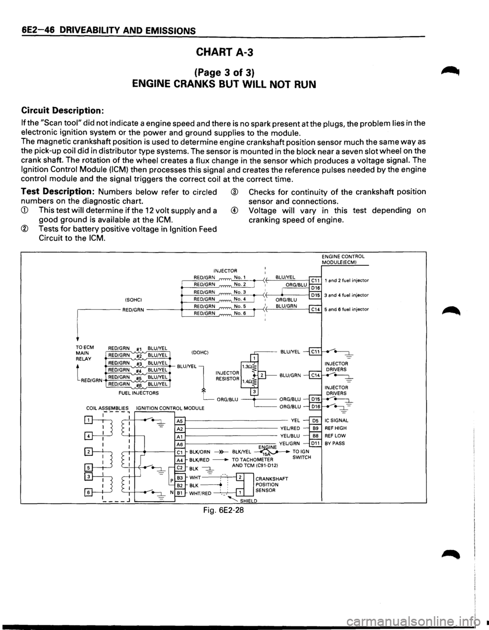
Circuit Description:
If the "Scan tool" did not indicate a engine speed and there is no spark present at the plugs, the problem lies in the
electronic ignition system
or the power and ground supplies to the module.
The magnetic crankshaft position is used to determine engine crankshaft position sensor much the same way as
the pick-up coil did in distributor type systems. The sensor is mounted in the block near a seven slot wheel on the
crank shaft. The rotation
of the wheel creates a flux change in the sensor which produces a voltage signal. The
Ignition Control Module (ICM) then processes this signal and creates the reference pulses needed by the engine
control module and the signal triggers the correct coil at the correct time.
Test Description: Numbers below refer to circled ® Checks for continuity of the crankshaft position
numbers on the diagnostic chart. sensor and connections.
available at the ICM. cranking speed of engine.
® Tests for battery positive voltage in Ignition Feed
Circuit to the
ICM.
TO ECM RED/GRN #1 BLU/YEL MAIN RELAY
tRED/GRN
RED/GRN #2 BLU/YEL
RED/GRN #3 BLU/YEL
RED/GRN '"#4 BLU/YEL RED/GRN #5 BLU/YEL RED/GRN #6 BLU/YEL
FUEL
INJECTORS INJECTOR
RED/GRN RED/GRN RED/GRN
E"'QINE YELJGRN D11 BLK!ORN ----)>--BLK!YEL _____..,-~ TO IGN BLK!RED
-TO TACHOMETER SWITCH BLK --:::J_ AND TCM (C91-D12)
WHT2cl]= :-·-, 2 CRANKSHAFT BLK ~ : POSITION WHT/RED · __ ,' 1 SENSOR
'-;SHIELD
Fig. 6E2-28
ENGINE CONTROL
MODULEIECM)
1 and 2 fuel injector
•
Page 768 of 1928
6E2-72 DRIVEABILITV AND EMISSIONS
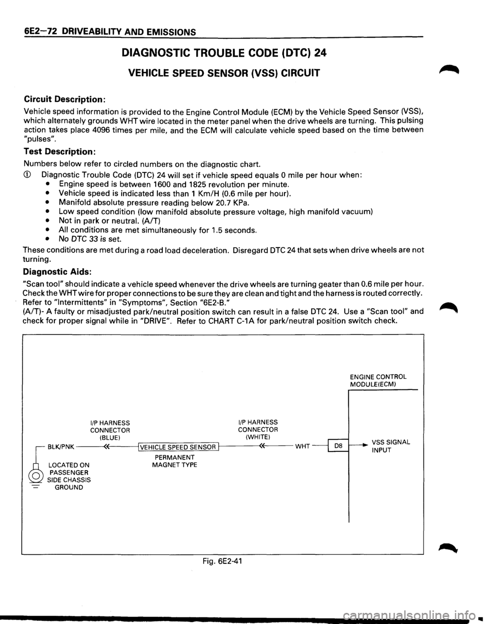
Circuit Description:
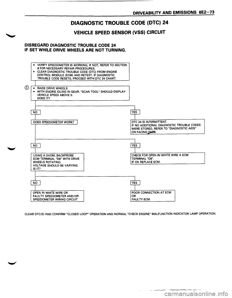
DIAGNOSTIC TROUBLE CODE (DTC) 24
VEHICLE SPEED SENSOR (VSS) CIRCUIT
Vehicle speed information is provided to the Engine Control Module (ECM) by the Vehicle Speed Sensor (VSS),
which alternately grounds WHT wire located in the meter panel when the drive wheels are turning. This pulsing
action takes place 4096 times per mile, and the ECM will calculate vehicle speed based on the time between
"pulses".
Test Description:
Numbers below refer to circled numbers on the diagnostic chart.
CD Diagnostic Trouble Code (DTC) 24 will set if vehicle speed equals 0 mile per hour when:
• Engine speed is between 1600 and 1825 revolution per minute.
• Vehicle speed is indicated less than 1 Km/H (0.6 mile per hour).
• Manifold absolute pressure reading below 20.7 KPa.
• Low speed condition (low manifold absolute pressure voltage, high manifold vacuum)
• Not in park or neutral. (A/T)
• All conditions are met simultaneously for 1.5 seconds.
• No DTC 33 is set.
These conditions are
met during a road load deceleration. Disregard DTC 24 that sets when drive wheels are not
turning.
Diagnostic Aids:
"Scan tool" should indicate a vehicle speed whenever the drive wheels are turning geater than 0.6 mile per hour.
Check the
WHTwire for proper connections to be sure they are clean and tight and the harness is routed correctly.
Refer to "lntermittents" in "Symptoms", Section "6E2-B."
(A/T)- A
faulty or misadjusted park/neutral position switch can result in a false DTC 24. Use a "Scan tool" and
check
for proper signal while in "DRIVE". Refer to CHART C-1A for park/neutral position switch check.
1/P HARNESS 1/P HARNESS CONNECTOR CONNECTOR ENGINE
CONTROL
MODULE(ECM) (BLUE) (WHITE)
BLK/PNK ----<:(-<---{IYJVE~Hi!IQCL~EjS~P~E~ED~S~EN~S~O~RUif-----<~•E---WHT ~ _____. ~~;U~IGNAL
PERMANENT LOCATED ON MAGNET TYPE PASSENGER SIDE CHASSIS
GROUND
Fig. 6E2-41
..
Page 769 of 1928
DRIVEABILITY AND EMISSIONS 6E2-73
DIAGNOSTIC TROUBLE CODE (DTC) 24
VEHICLE SPEED SENSOR (VSS) CIRCUIT
DISREGARD DIAGNOSTIC TROUBLE CODE 24
IF SET WHILE DRIVE WHEELS ARE NOT TURNING.
• VERIFY SPEEDOMETER IS WORKING, IF NOT, REFER TO SECTION 8 FOR NECESSARY REPAIR PROCEDURES. • CLEAR DIAGNOSTIC TROUBLE CODE (DTC) FROM ENGINE CONTROL MODULE (ECM) AND RETEST. IF DIAGNOSTIC TROUBLE CODE RESETS, PROCEED WITH DTC 24 CHART.
CD • RAISE DRIVE WHEELS • WITH ENGINE IDLING IN GEAR, "SCAN TOOL" SHOULD DISPLAY VEHICLE SPEED ABOVE 0. DOES IT?
$ ~
DOES SPEEDOMETER WORK? I DTC 24 IS INTERMITIENT. IF NO ADDITIONAL DIAGNOSTIC TROUBLE CODES WERE STORED, REFER TO "DIAGNOSTIC AIDS" ON FACING~.
CfJ ~ USING A DVOM, BACKPROBE CHECK FOR OPEN IN WHITE WIRE A ECM
ECM TERMINAL "D8" WITH DRIVE TERMINAL "D8". WHEELS ROTATING. IF OK REPLACE ECM. VOLTAGE SHOULD BE VARYING. IS IT?
$ ~ OPEN IN WHITE WIRE OR POOR CONNECTION AT ECM FAULTY SPEEDOMETER AND/OR OR SPEEDOMETER WIRING CIRCUIT FAULTY ECM
CLEAR DTC(S) AND CONFIRM "CLOSED LOOP" OPERATION AND NORMAL "CHECK ENGINE" MALFUNCTION INDICATOR LAMP OPERATION.
-~---
Page 800 of 1928
6E2-1 04 DRIVEABILITV AND EMISSIONS
Engine Coolant Temperature (ECT) Sensor
A "Scan tool" displays engine temperature in degrees
centigrade. After engine is started, the temperature
should rise steadily to about 90°C then stabilize when
thermostat opens. If the engine has not been run for
several hours (overnight), the engine coolant
temperature (ECT) and intake air temperature (IAT)
readings should be close to each other. A fault in the
ECT sensor circuit should set a diagnostic trouble code
(DTC) 14. The DTC charts also contain a chart to check
for sensor resistance values relative to temperature.
Intake Air Temperature (IAT) Sensor
A "Scan tool" displays temperature of the air entering
the engine and
should read close to ambient air
temperature when engine
is cold, and rise as under
hood temperature increases.
If the engine has not
been run for several hours (overnight), the IAT sensor
temperature and
ECT readings should be close to each
other. A
failure in the IAT sensor circuit should set a
DTC 23. The DTC charts also contain a chart to check
for sensor resistance values relative to temperature.
Heated Oxygen Sensor (H02S)
The "Scan tool" has several positions that will indicate
the state
of the exhaust gases, Oxygen voltage,
integrator, and block learn. See "Scan tool" position
information in
"Introduction", "Driveability and
Emission," in this section.
A
problem in the oxygen sensor circuit, or fuel system,
should set a DTC 13 (open circuit), DTC 44 (lean
indication)/DTC 45 (rich indication). Refer to
applicable chart, if any of these DTC(s) were stored in
memory.
Throttle Position (TP) Sensor
A "Scan tool" displays throttle position in volts. On 3.2L
engine, Throttle position
(TP) sensor voltage should
read below 0.85 volts, with throttle closed and ignition
"ON", or at idle. Voltage should increase at a steady
rate
as throttle is moved toward wide open throttle.
The Engine
Control Module (ECM) has the ability to
auto-zero the TP sensor voltage if it is below about 0.85
volts. This means that any voltage less than 0.85 volts
will
be determined by the ECM to be 0% throttle.
Some
"Scan tools" have the ability to read the throttle
angle and should read 0%, when the throttle is closed.
A failure in the TP sensor or circuit should set a DTC 21.
Manifold Absolute Pressure (MAP) Sensor
"Scan tool" displays manifold pressure in volts. Low
pressure (high vacuum) reads a
low voltage, while a
high pressure
(low vacuum) reads a high voltage. A
failure in the Manifold Absolute Pressure (MAP) sensor
circuit
should set a DTC 33 and using the chart will find
the cause
of the problem. A DTC 33 may be set if a
rough or unstable
idle exists. CHART C-1 D can also be
used
to check MAP sensor.
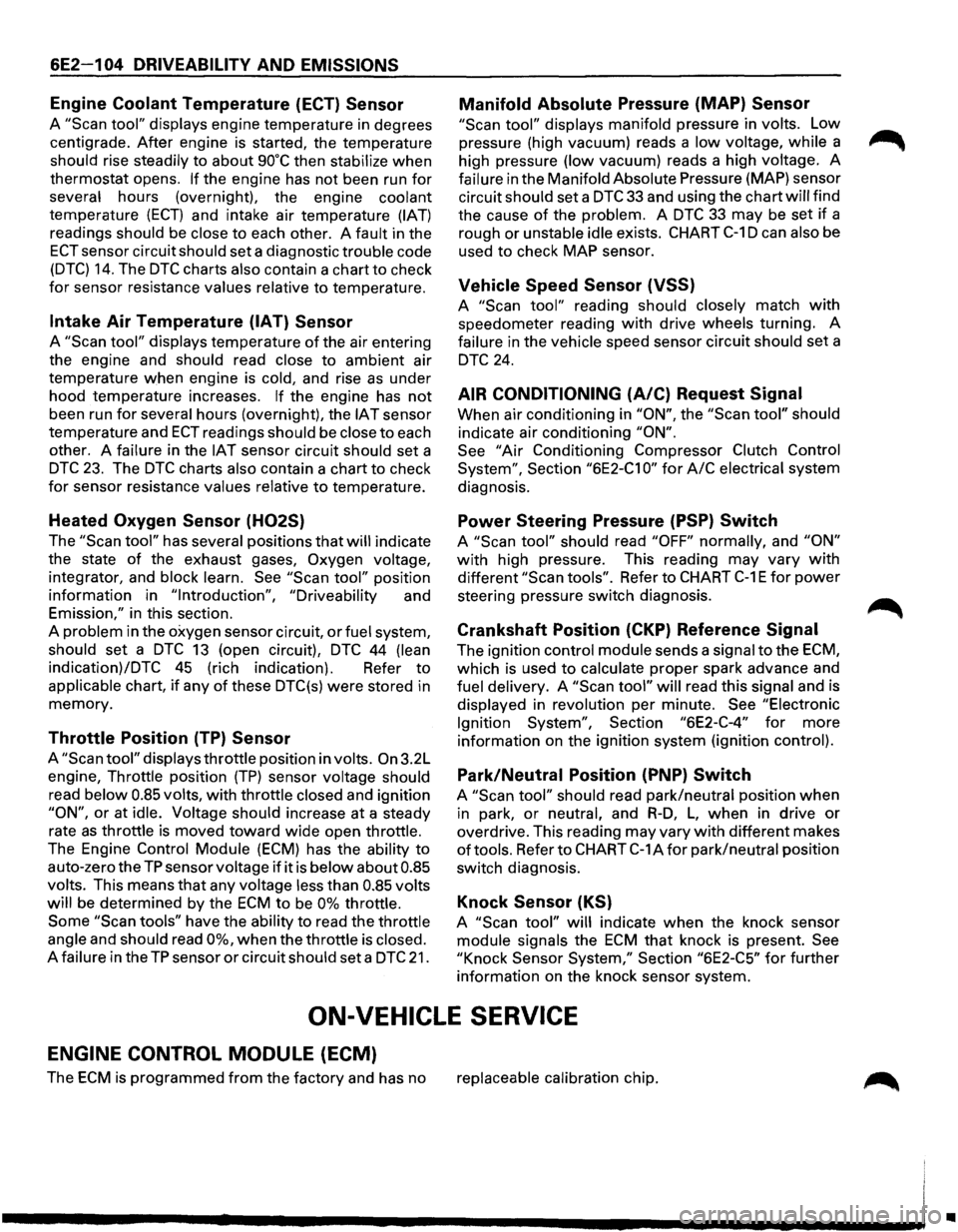
Vehicle Speed Sensor (VSS)
A "Scan tool" reading should closely match with
speedometer reading with drive wheels turning. A
failure in the vehicle speed sensor circuit should set a
DTC 24.
AIR CONDITIONING (A/C) Request Signal
When air conditioning in "ON", the "Scan tool" should
indicate air conditioning "ON".
See
"Air Conditioning Compressor Clutch Control
System",
Section "6E2-C1 0" for A/C electrical system
diagnosis.
Power Steering Pressure (PSP) Switch
A "Scan tool" should read "OFF" normally, and "ON"
with high pressure. This reading may vary with
different "Scan tools". Refer to CHART C-1 E for power
steering pressure switch diagnosis.
Crankshaft Position (CKP) Reference Signal
The ignition control module sends a signal to the ECM,
which is used to calculate proper spark advance and
fuel delivery. A "Scan tool" will read this signal and is
displayed in revolution per minute.
See "Electronic
Ignition System",
Section "6E2-C-4" for more
information on the ignition system (ignition control).
Park/Neutral Position (PNP) Switch
A "Scan tool" should read park/neutral position when
in park, or neutral, and R-D, L, when in drive or
overdrive. This reading may vary with different makes
of tools. Refer to CHART C-1 A for park/neutral position
switch diagnosis.
Knock Sensor (KS)
A "Scan tool" will indicate when the knock sensor
module signals the ECM that knock is present. See
"Knock
Sensor System," Section "6E2-C5" for further
information on the knock sensor system.
ON-VEHICLE SERVICE
ENGINE CONTROL MODULE (ECM)
The ECM is programmed from the factory and has no replaceable calibration chip.
•