wheel ISUZU TROOPER 1995 Workshop Manual
[x] Cancel search | Manufacturer: ISUZU, Model Year: 1995, Model line: TROOPER, Model: ISUZU TROOPER 1995Pages: 1928
Page 914 of 1928
7 A-42 AUTOMATIC TRANSMISSION (4L30-E)
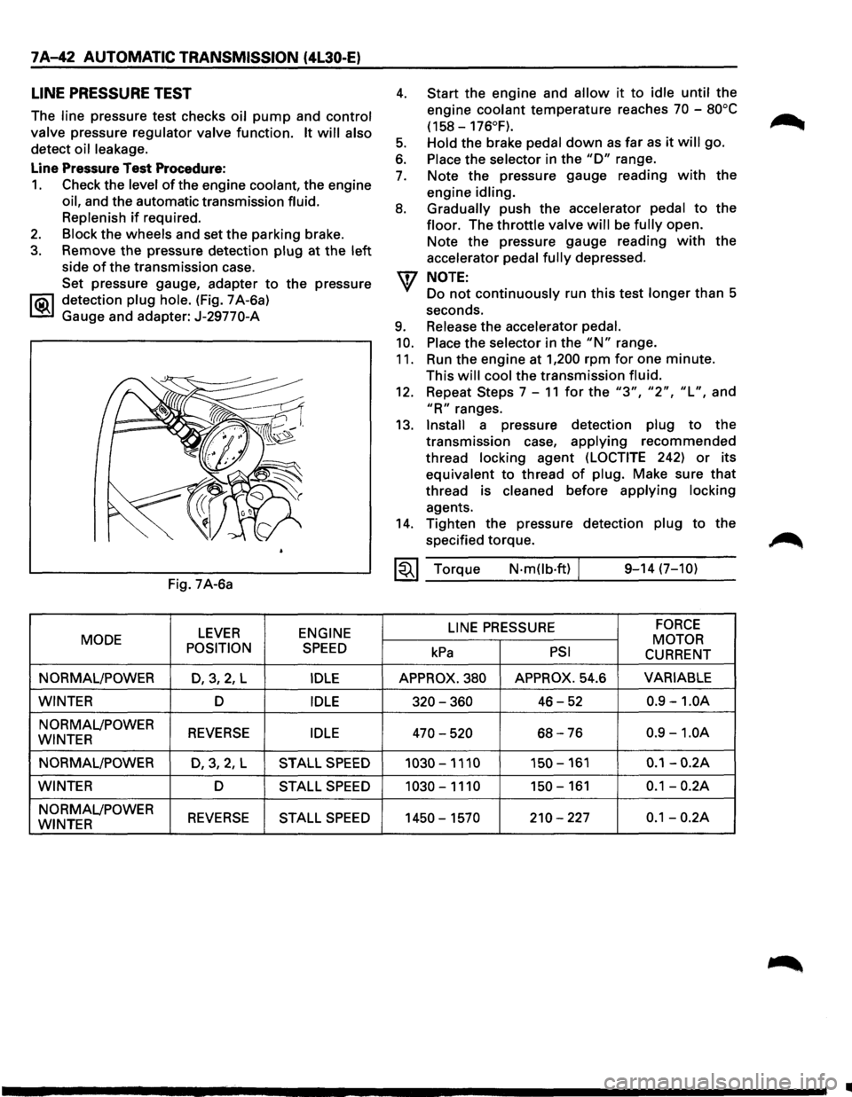
LINE PRESSURE TEST
The line pressure test checks oil pump and control
valve
pressure regulator valve function. It will also
detect oil leakage.
Line Pressure Test Procedure:
1. Check the level of the engine coolant, the engine
oil, and the automatic transmission fluid.
Replenish
if required.
2. Block the wheels and set the parking brake.
3. Remove the pressure detection plug at the left
side of the transmission case.
Set pressure gauge, adapter
to the pressure
l"iC\1 detection plug hole. (Fig. 7 A-6a)
~ Gauge and adapter: J-29770-A
Fig. 7A-6a
LEVER ENGINE
MODE
POSITION
SPEED
NORMAL/POWER D,3,2, L IDLE
WINTER D IDLE
NORMAL/POWER REVERSE IDLE WINTER
NORMAL/POWER
D,3,2,L STALL SPEED
WINTER D STALL SPEED
NORMAL/POWER REVERSE STALL SPEED WINTER
4.
5.
6.
7.
8.
9.
10.
11.
Start the engine and allow it to idle until the
engine
coolant temperature reaches 70 -80°C
(158-176°F).
Hold
the brake pedal down as far as it will go.
Place the selector in the "D" range.
Note the pressure gauge reading
with the
engine
idling.
Gradually
push the accelerator pedal to the
floor. The throttle valve will be fully open.
Note the pressure gauge reading
with the
accelerator
pedal fully depressed.
NOTE:
Do not continuously run this test longer than 5
seconds.
Release the accelerator pedal.
Place
the selector in the "N" range.
Run the engine at
1,200 rpm for one minute.
This
will cool the transmission fluid.
12. Repeat Steps 7-11 for the "3", "2", "L", and
"R" ranges.
13.
Install a pressure detection plug to the
transmission case,
applying recommended
thread
locking agent (LOCTITE 242) or its
equivalent to thread
of plug. Make sure that
thread is cleaned before applying locking
agents.
14. Tighten the pressure detection plug to the
specified torque.
~~~ Torque N·mOb·ft) / 9-14 (7-10)
LINE
PRESSURE FORCE
MOTOR kPa PSI CURRENT
APPROX. 380 APPROX. 54.6 VARIABLE
320-360 46-52 0.9 -1.0A
470-520 68-76 0.9 -1.0A
1030-1110 150-161 0.1-0.2A
1030-1110 150-161 0.1-0.2A
1450-1570 210-227 0.1-0.2A
•
Page 935 of 1928
AUTOMATIC TRANSMISSION (4L30-E) 7 A-63
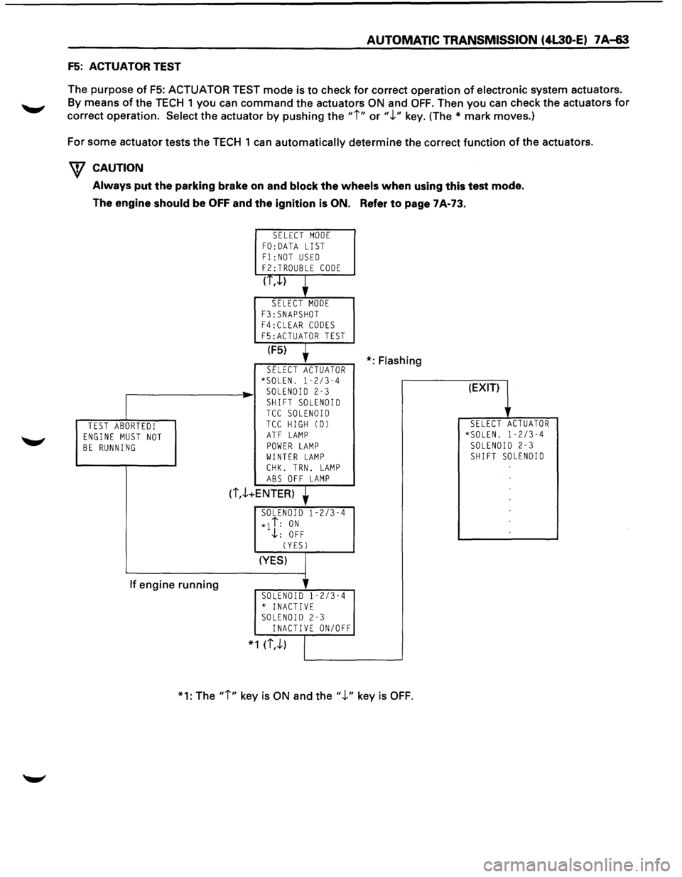
F5: ACTUATOR TEST
The purpose
of F5: ACTUATOR TEST mode is to check for correct operation of electronic system actuators.
By means of the TECH 1 you can command the actuators ON and OFF. Then you can check the actuators for
correct operation.
Select the actuator by pushing the "i" or".!." key. (The* mark moves.)
For some actuator tests the TECH 1
can automatically determine the correct function of the actuators.
W CAUTION
Always put the parking brake on and block the wheels when using this test mode.
The engine
should be OFF and the ignition is ON. Refer to page 7A-73.
TEST ABORTED! ENGINE MUST NOT BE RUNNING
If engine running
SELECT MODE FO: DATA LIST
F1:NOT USED F2:TROUBLE CODE
(T,.J..)
SELECT MODE
F3:SNAPSHOT F4:CLEAR CODES
F5:ACTUATOR TEST
(F5)
SELECT ACTUATOR *SOLEN. 1-2/3-4 SOLENOID 2-3
SHIFT SOLENOID TCC SOLENOID TCC HIGH CD)
ATF LAMP POWER LAMP WINTER LAMP
CHK. TRN. LAMP ABS OFF LAMP
(i,.!.+ENTER)
SOLENOID 1-2/3-4
*1 i: ON .j,: OFF
CYESJ
(YES)
SOLENOID 1-2/3-4 * INACTIVE SOLENOID 2-3 INACTIVE ON/OFF
* 1 (i,.!.)
*:Flashing
*1: The
"i" key is ON and the".!." key is OFF.
(EXIT)
SELECT ACTUATOR *SOLEN. 1-2/3-4 SOLENOID 2-3 SHIFT SOLENOID
Page 946 of 1928
7 A-74 AUTOMATIC TRANSMISSION (4l30-E)
DIAGNOSTIC TROUBLE CODE (DTC) 11
OUTPUT SPEED FAILURE
This DTC flashes the CHECK TRANS indicator and
sets the
BACKUP MODE.
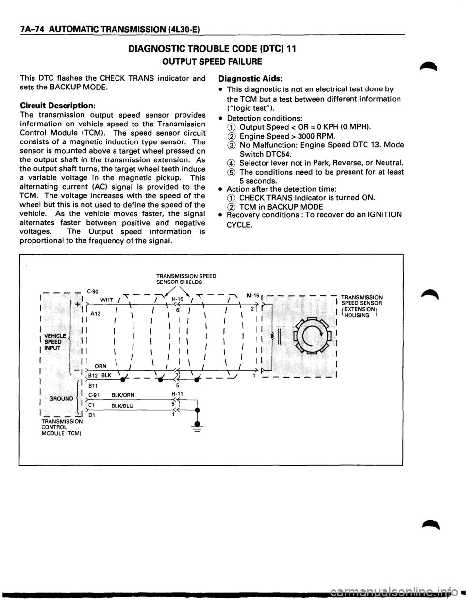
Circuit Description:
The transmission output speed sensor provides
information on vehicle speed to the Transmission
Control Module (TCM). The speed sensor circuit
consists
of a magnetic induction type sensor. The
sensor is
mounted above a target wheel pressed on
the
output shaft in the transmission extension. As
the
output shaft turns, the target wheel teeth induce
a variable voltage in the magnetic pickup. This
alternating current
(AC) signal is provided to the
TCM. The voltage increases with the speed of the
wheel
but this is not used to define the speed of the
vehicle. As the vehicle
moves faster, the signal
alternates faster between positive and negative
voltages. The
Output speed information is
proportional to the frequency of the signal.
TRANSMISSION SPEED SENSOR SHIELDS
Diagnostic Aids:
• This diagnostic is not an electrical test done by
the TCM but a test between different information
("logic test").
• Detection conditions:
CD Output Speed < OR = 0 KPH (0 MPH).
® Engine Speed > 3000 RPM.
@ No Malfunction: Engine Speed DTC 13. Mode
Switch DTC54.
@ Selector lever not in Park, Reverse, or Neutral.
@ The conditions need to be present for at least
5 seconds.
• Action after the detection time:
CD CHECK TRANS Indicator is turned ON.
® TCM in BACKUP MODE
•
Recovery conditions :To recover do an IGNITION
CYCLE.
- - -,.,.. C-90 "" - -~ ~ ""\' - -:-' M-15 r - - - - - - -TRANSMISSION I I WHT I , I , H<~o I , I , t , I SPEED SENSOR I +I > I I I I 6 I I I I 2 I (EXTENSION) I A12 I I I HOUSING
I II 111
11111111 ©I
', VEHICLE ', II I
I I I I I I I I I I !I ' ,~, 1
:
SPEED . I I I I I I I I I II "-.
I INPUT I I I I I I I I I I
I I I
ORN I I I I I I I I
I
-1 ~812 BLK l-- -~b - -~ ,> - - - - - - -I
I ll B11 s
I GROUND I C-91 BLK/ORN H-9_11
I I I C1 BLK/BLU : I
J __ -_I D1
TRANSMISSION
CONTROL MODULE
(TCM)
•
Page 947 of 1928
AUTOMATIC TRANSMISSION (4L30·E) 7 A-75
DIAGNOSTIC TROUBLE CODE (DTC) 11
OUTPUT SPEED FAILURE
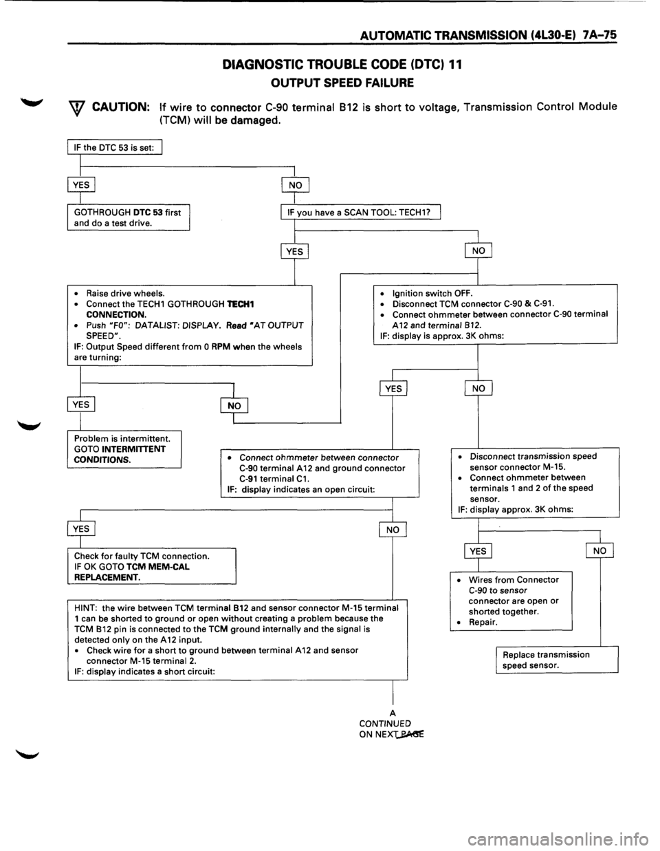
W CAUTION: If wire to connector C-90 terminal 812 is short to voltage, Transmission Control Module
(TCM) will be damaged.
IF the DTC 53 is set:
I I
~
GOTH ROUGH DTC 53 first J I IF you have a SCAN TOOL: TECH17 I and do a test drive. I
cf
$
• Raise drive wheels. • Ignition switch OFF.
• Connect the TECH1 GOTH ROUGH TECH1 • Disconnect TCM connector C-90 & C-91.
CONNECTION. • Connect ohmmeter between connector C-90 terminal
• Push "FO": DATALIST: DISPLAY. Read •AT OUTPUT A12 and terminal 812 . SPEED". IF: display is approx. 3K ohms: IF: Output Speed different from 0 RPM when the wheels are turning:
diJ
§J
$
T
Problem is intermittent. GOTO INTERMITTENT
CONDITIONS. • Connect ohmmeter between connector C-90 terminal A12 and ground connector C-91 terminal C1.
IF: display indicates an open circuit:
$ ~
Check for faulty TCM connection. IF OK GOTO TCM MEM-CAL
REPLACEMENT.
HINT: the wire between TCM terminal 812 and sensor connector M-15 terminal 1 can be shorted to ground or open without creating a problem because the TCM 812 pin is connected to the TCM ground internally and the signal is
detected only on the A 12 input.
• Check wire for a short to ground between terminal A 12 and sensor
connector M-15 terminal 2. IF: display indicates a short circuit:
I
A CONTINUED
ONNEX~
NO
• Disconnect transmission speed
sensor connector M-15.
• Connect ohmmeter between terminals 1 and 2 of the speed
sensor.
IF: display approx. 3K ohms:
$ ~
• Wires from Connector C-90 to sensor
connector are open or shorted together.
• Repair .
I Replace transmission
speed sensor.
Page 1006 of 1928
7A-134 AUTOMATIC TRANSMISSION (4L30-E)
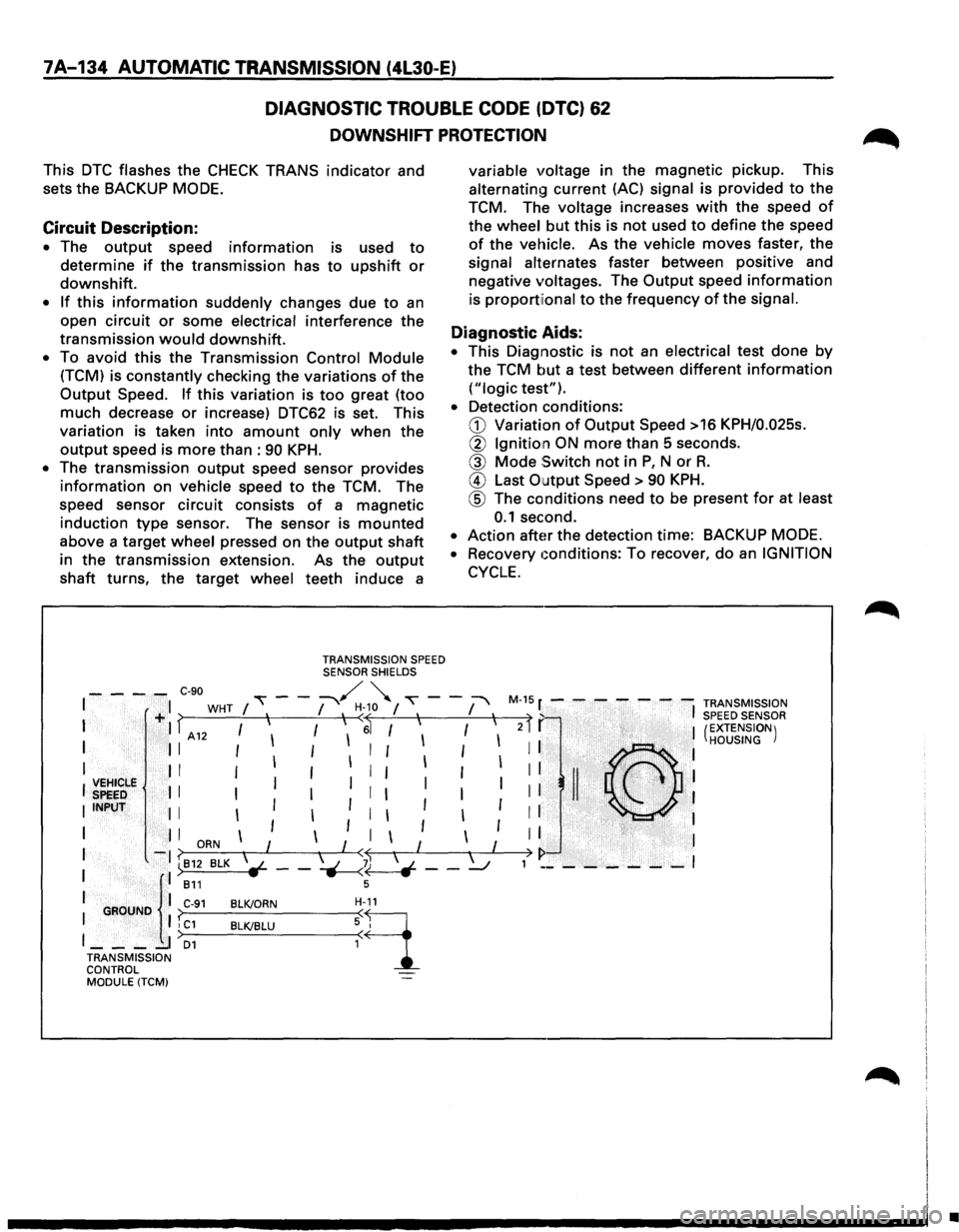
DIAGNOSTIC TROUBLE CODE (DTC) 62
DOWNSHIFT PROTECTION
This DTC flashes the CHECK TRANS indicator and
sets the
BACKUP MODE.
Circuit Description:
• The output speed information is used to
determine if the transmission has to upshift or
downshift.
• If this information suddenly changes due to an
open circuit or some electrical interference the
transmission
would downshift.
• To avoid this the Transmission Control Module
(TCM) is constantly checking the variations of the
Output Speed. If this variation is too great (too
much decrease
or increase) DTC62 is set. This
variation is taken into
amount only when the
output speed is more than : 90 KPH.
• The transmission output speed sensor provides
information on vehicle speed to the TCM. The
speed sensor circuit consists
of a magnetic
induction
type sensor. The sensor is mounted
above a target wheel pressed on the output shaft
in the transmission extension. As the
output
shaft turns, the target wheel teeth induce a
TRANSMISSION SPEED SENSOR SHIELDS
variable voltage in the magnetic pickup. This
alternating current (AC) signal is provided to the
TCM. The
voltage increases with the speed of
the wheel but this is not used to define the speed
of the vehicle. As the vehicle moves faster, the
signal alternates faster between positive and
negative
voltages. The Output speed information
is proportiional to the frequency of the signal.
Diagnostic Aids:
• This Diagnostic is not an electrical test done by
the TCM but a test between different information
("logic test").
• Detection conditions:
G) Variation of Output Speed >16 KPH/0.025s.
@ Ignition ON more than 5 seconds.
@ Mode Switch not in P, N or R.
@ Last Output Speed > 90 KPH.
@ The conditions need to be present for at least
0.1 second.
• Action after the detection time: BACKUP MODE.
•
Recovery Gonditions: To recover, do an IGNITION
CYCLE.
- - - -C-90 / " I ,---:-"'\. '-. ~---+I WHT I I I I ~-10 I 'I I 'I M-1
5 r - - - - - - -TRANSMISSION ) f I SPEED SENSOR I . I f A 12 I I I I ~ I I I I
I II I I I I I I I I I
I II I I I I 1 I I
~~~~rie II I Ill I I
IINPUT II I I I I
1 1 1 I l I I I I -? ORN I I < I I
I l: ):~~ BLK \~ __ ~~ __ ~
I GROUNO I C-91 BLK/ORN H-11
I I I C1 BLK/BLU ~ 9_ I ____ I D1
TRANSMISSION
CONTROL MODULE (TCM)
2 I I (EXTENSION)
: : .·(C},h.·.. ,.·, .. ·.,· .. : HOUSING
II II ·<;',~ . I
I I . 'I ' . . I
I I I
) I> 1 ________ I
•
Page 1007 of 1928
AUTOMATIC TRANSMISSION (4l30-E) 7 A .... 135
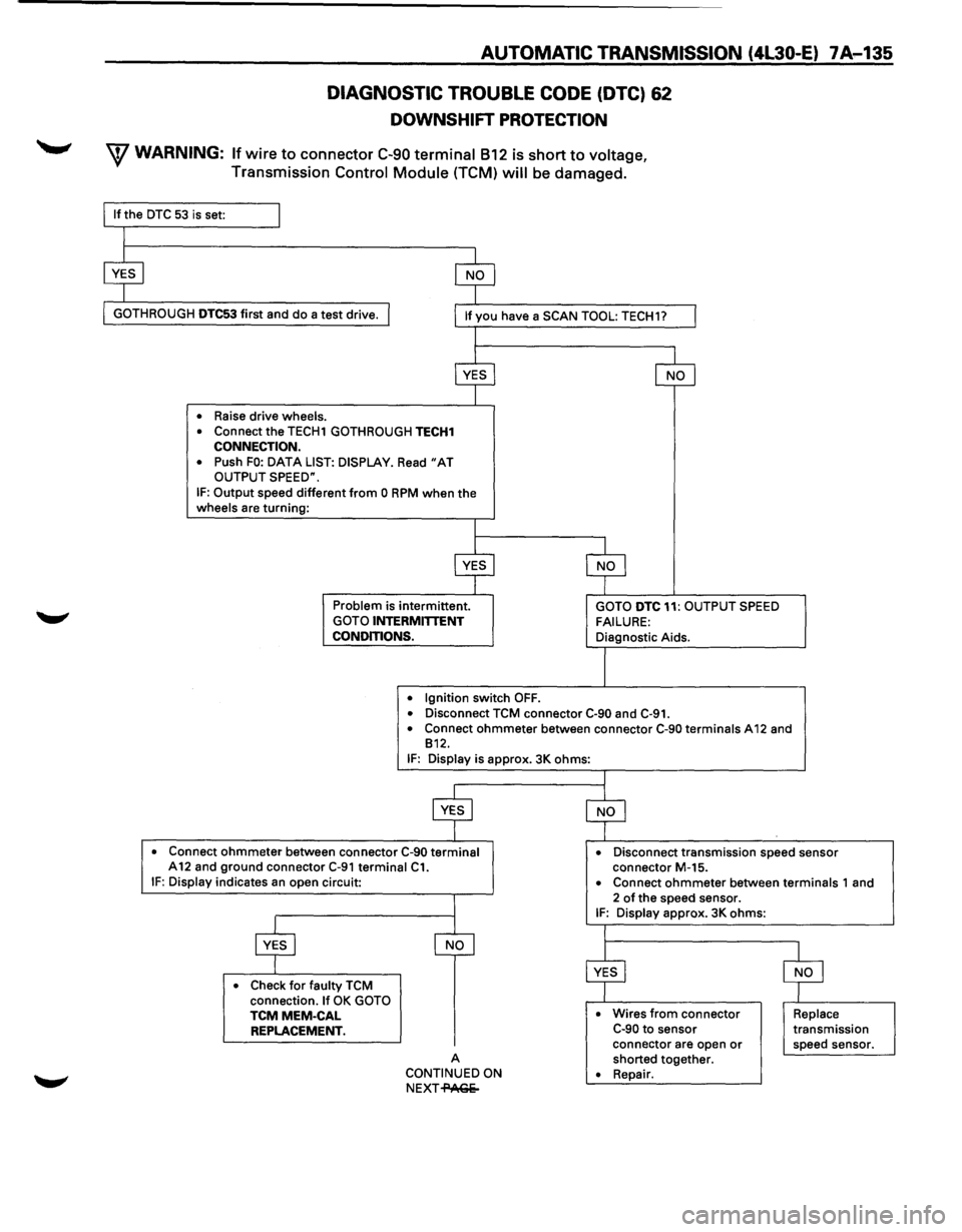
DIAGNOSTIC TROUBLE CODE (DTC) 62
DOWNSHIFT PROTECTION
W WARNING: If wire to connector C-90 terminal 812 is short to voltage,
Transmission Control Module (TCM) will be damaged.
GOTH ROUGH DTC53 first and do a test drive.
• Raise drive wheels.
•
Connect the TECH1 GOTHROUGH TECH1 CONNECTION.
•
Push FO: DATA LIST: DISPLAY. Read "AT OUTPUT SPEED".
IF: Output speed different from 0 RPM when the wheels are turning:
Problem is intermittent. GOTO INTERMITTENT
CONDITIONS.
•
Ignition switch OFF.
GOTO DTC 11: OUTPUT SPEED
FAILURE: Diagnostic Aids.
• Disconnect TCM connector C·90 and C-91. • Connect ohmmeter between connector C-90 terminals A 12 and
812.
IF: Display is approx. 3K ohms:
• Connect ohmmeter between connector C-90 terminal A12 and ground connector C-91 terminal C1. • Disconnect transmission speed sensor
connector M-15.
IF: Display indicates an open circuit:
• Check for faulty TCM
connection. If OK GOTO TCMMEM-CAL REPLACEMENT.
A
CONTINUED ON
NEXT-PAGe- •
Connect ohmmeter between terminals 1
and
2 of the speed sensor. IF: Display approx. 3K ohms:
• Wires from connector C-90 to sensor
connector are open or shorted together. • Repair.
Replace transmission
speed sensor.
Page 1032 of 1928
7A-160 AUTOMATIC TRANSMISSION (4L30-E)
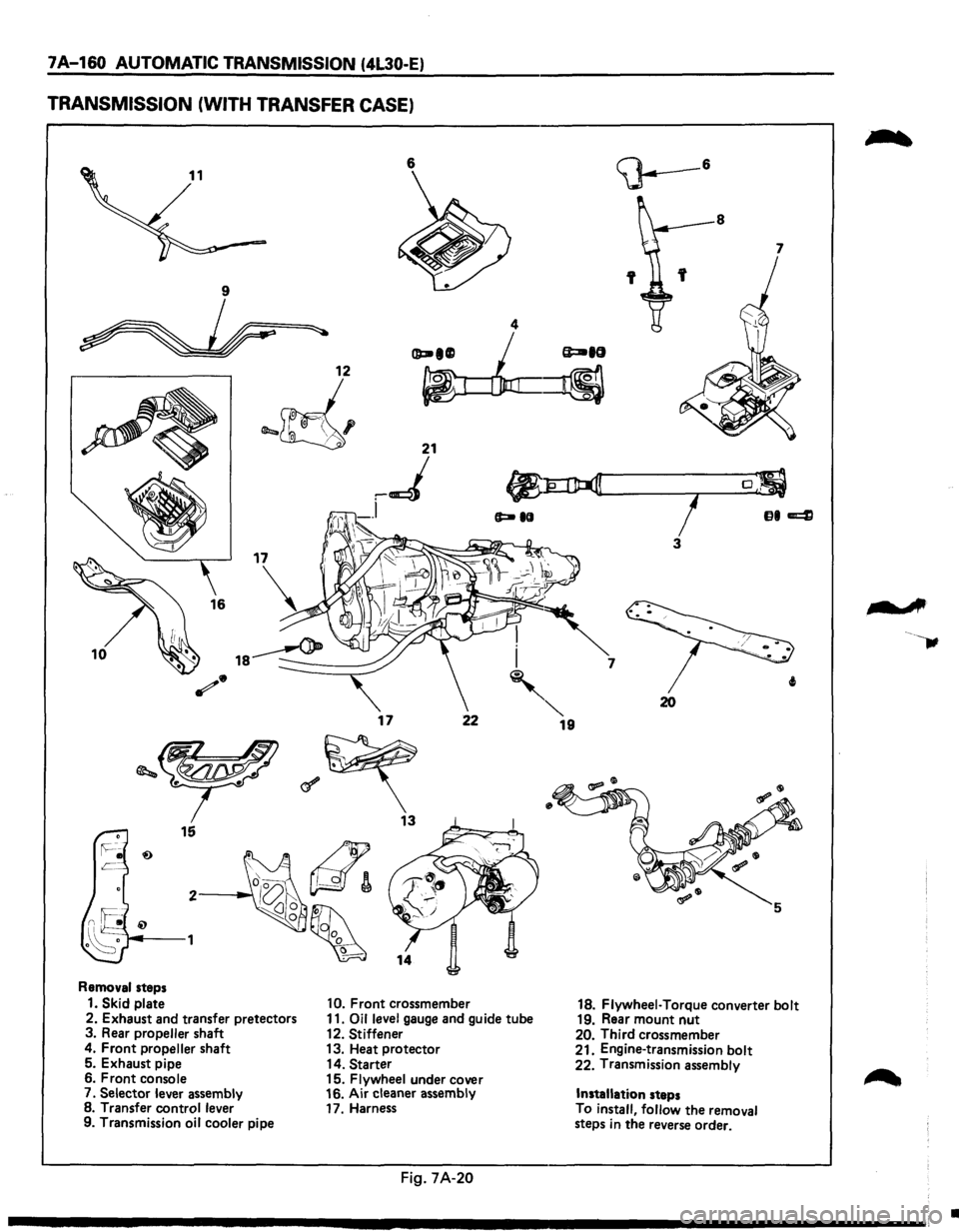
TRANSMISSION (WITH TRANSFER CASE)
6
I
10 i
'
17 22
Removal steps
1. Skid plate 10. Front crossmember
2. Exhaust and transfer pretectors 11. Oil level gauge and guide tube
3. Rear propeller shaft
12. Stiffener
4. Front propeller shaft 13. Heat protector
5. Exhaust pipe
14. Starter
6. Front console
15. Flywheel under cover
7.
Selector lever assembly 16.
Air cleaner assembly
8. Transfer control lever
17. Harness
9. Transmission
oil cooler pipe
Fig. 7A-20
""' 19
8
7
7
20
18. Flywheel· Torque converter bolt 19. Rear mount nut 20. Third crossmember
21. Engine-transmission bolt
22. Transmission assembly
Installation steps
To
install, follow the removal
steps in the reverse order.
-A
•
Page 1034 of 1928
7A-162 AUTOMATIC TRANSMISSION (4L30-E)
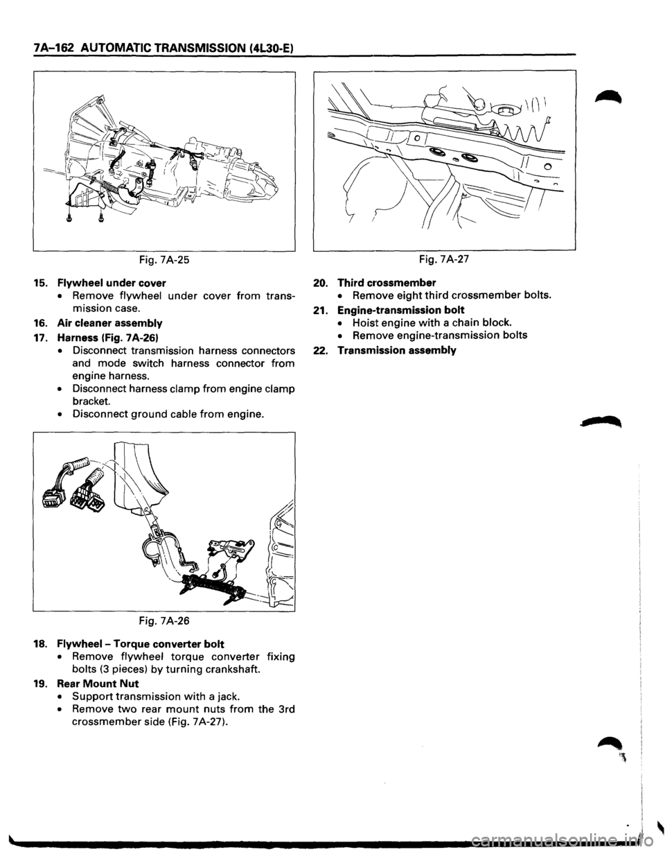
Fig. 7A-25
15. Flywheel under cover
• Remove flywheel under cover from trans
mission case.
16. Air cleaner assembly
17. Harness (Fig. 7A-26)
• Disconnect transmission harness connectors
and mode switch harness connector
from
engine harness.
• Disconnect harness clamp from engine clamp
bracket.
• Disconnect ground cable from engine.
Fig. 7A-26
18. Flywheel-Torque converter bolt
• Remove flywheel torque converter fixing
bolts (3 pieces) by turning crankshaft.
19. Rear Mount Nut
• Support transmission with a jack.
• Remove two rear mount nuts from the 3rd
crossmember side (Fig. 7A-27). Fig.
7A-27
20. Third cr·ossmember
• Remove eight third crossmember bolts.
21. Engine-transmission bolt
• Hoist engine with a chain block.
•
Remove engine-transmission bolts
22. Transmission assembly
Page 1036 of 1928
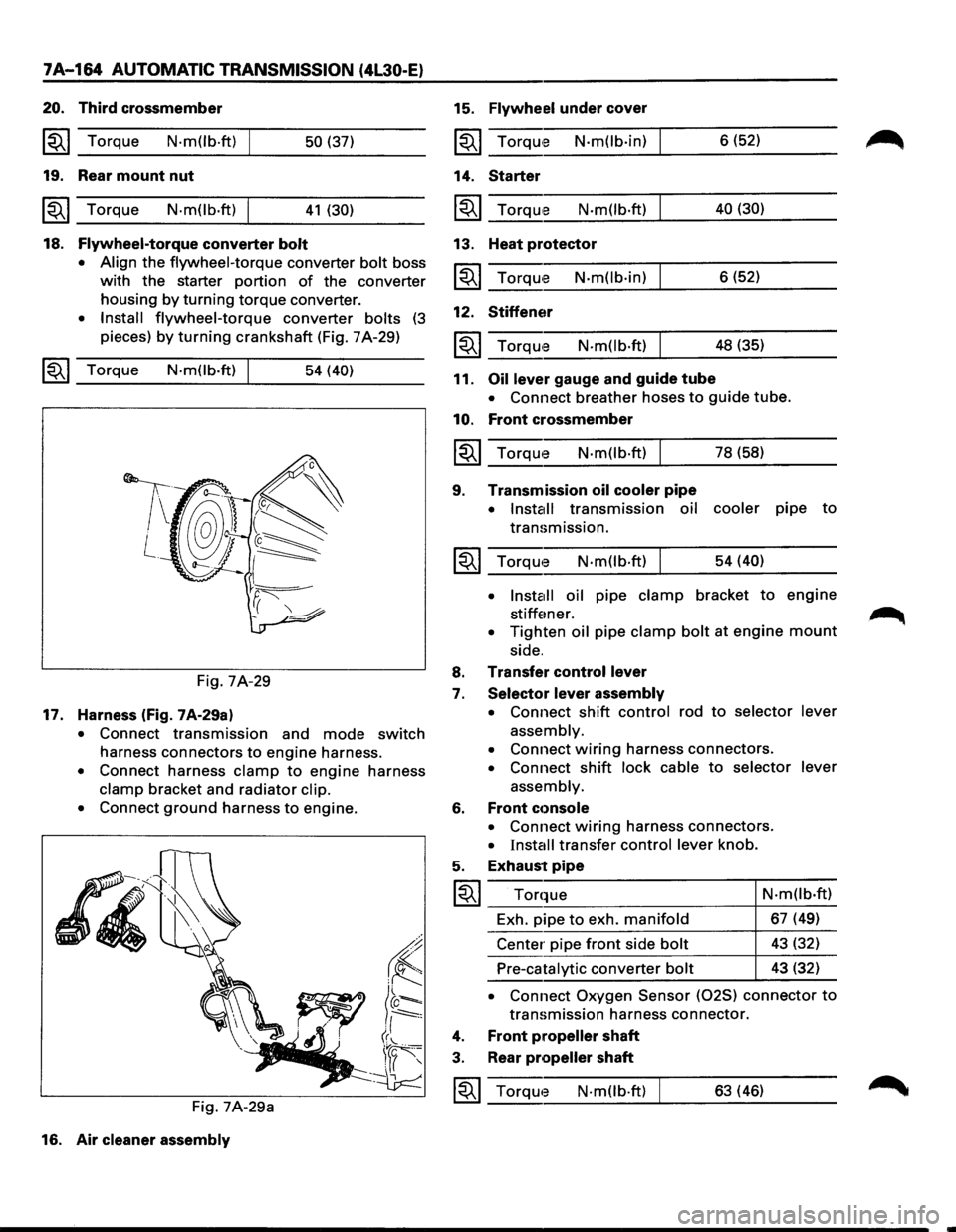
7A-164 AUTOMATIC TRANSMISSION (4L30-E)
20. Third crossmember
~~~ Torque N·m(lb.ft) 50 (37)
19. Rear mount nut
~~~ Torque N·mOb·ft) 41 (30)
18. Flywheel-torque converter bolt
• Align
the flywheel-torque converter bolt boss
with the starter portion of the converter
housing
by turning torque converter.
• Install flywheel-torque converter bolts (3
pieces) by turning crankshaft (Fig. 7 A-29)
~~~ Torque N·mOb·ft) 54 (40)
Fig. 7A-29
17. Harness (fig. 7A-29a)
• Connect transmission and mode switch
harness connectors to engine harness.
• Connect harness clamp to engine harness
clamp bracket and radiator clip.
•
Connect ground harness to engine.
Fig. 7A-29a
16. Air
cleaner assembly
15. Flywheel under cover
~~~ TorqUte N·mOb·in)
14. Starter
~~~ Torqu,e N·m(lb·ft)
13. Heat protector
~~~ Torqu'e N·m(lb·in)
12. Stiffener
N·m(lb·ft)
11. Oil lever gauge and guide tube 6
(52)
40 (30)
6 (52)
48 (35)
• Connect breather hoses to guide tube.
10. Front crossmember
~~~ Torque N·m(lb·ft) I 78 (58)
9. Transmission oil cooler pipe
• Install transmission oil cooler pipe to
transmission.
~~~ Torqwe N·m(lb·ft) I 54 (40)
•
lnsta1ll oil pipe clamp bracket to engine
stiffener. .~
• Tighten oil pipe clamp bolt at engine mount
side.
8. Transfer control lever
7. Selector lever assembly
•
Connect shift control rod to selector lever
assembly.
•
Connect wiring harness connectors.
• Connect shift lock cable to selector lever
assembly.
6. Front cc>nsole
• Connect wiring harness connectors.
• Install transfer control lever knob.
5. Exhaust pipe
I~I ___ T_o_r_q~_ue __________________ 4-N_·_m_(l_b_·ft __ )
Exh. pipe
to exh. manifold 67 (49)
Center pipe
front side bolt 43 (32)
Pre-catalytic converter bolt 43 (32)
• Connect Oxygen Sensor (025) connector to
transmission harness connector.
4. Front propeller shaft
3. Rear propeller shaft
~~~ Torqwe N·mOb·ft) 63 (46)
Page 1047 of 1928
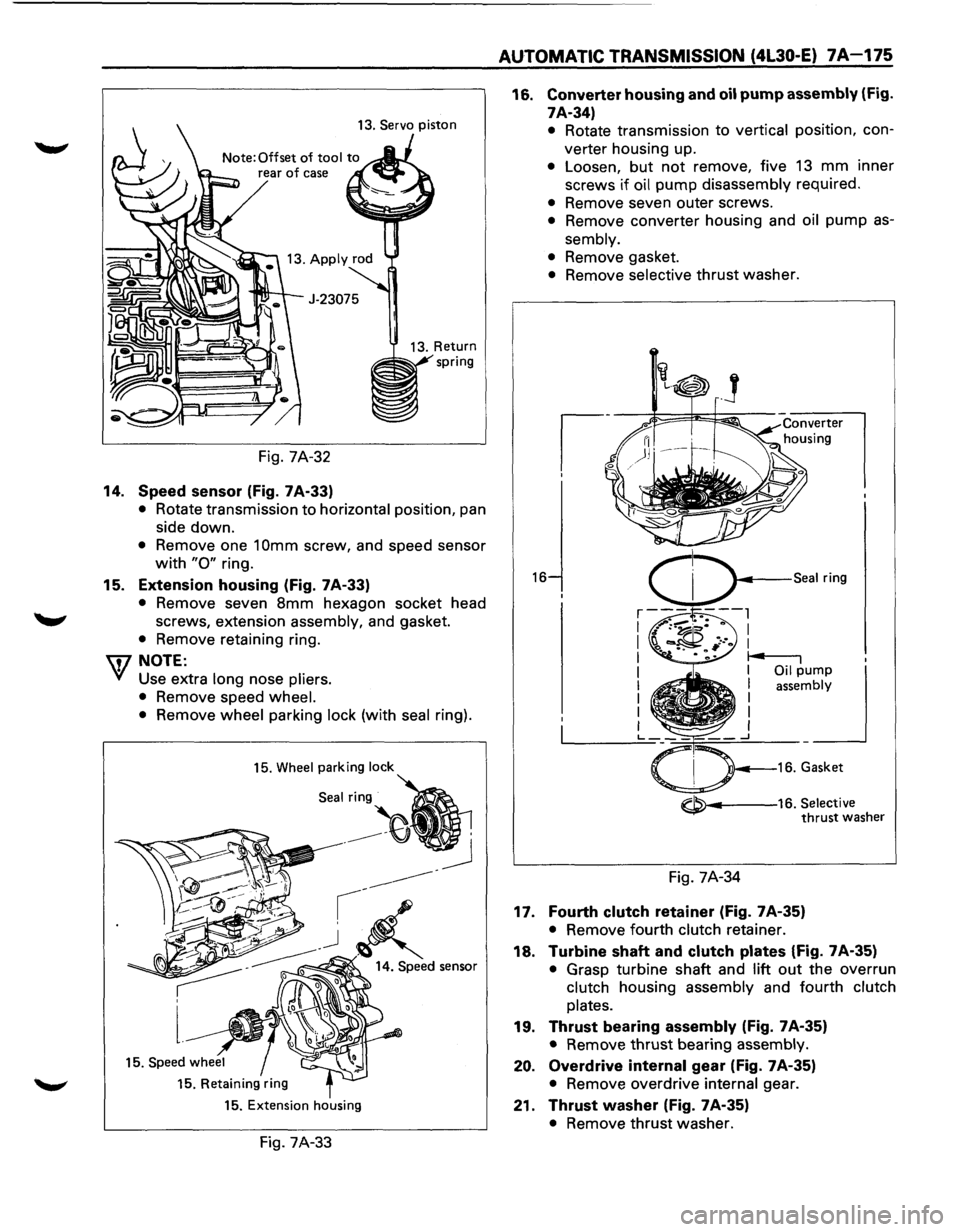
13. Servo piston
Fig. 7A-32
14. Speed sensor (Fig. 7A-33)
• Rotate transmission to horizontal position, pan
side down.
• Remove one 1 Omm screw, and speed sensor
with "0" ring.
15. Extension housing (Fig. 7 A-33)
• Remove seven 8mm hexagon socket head
screws, extension assembly, and gasket.
• Remove retaining ring.
\fl NOTE:
V Use extra long nose pliers.
• Remove speed wheel.
• Remove wheel parking lock (with seal ring).
15. Wheel parking lock
Seal:~
15. Retaining ring
15. Extension housing
Fig. 7A-33
AUTOMATIC TRANSMISSION (4L30-E) 7A-175
16. Converter housing and oil pump assembly (Fig.
7A-34)
16
• Rotate transmission to vertical position, con
verter housing up.
• Loosen, but not remove, five 13 mm inner
screws
if oil pump disassembly required.
• Remove seven outer screws.
• Remove converter housing and oil pump as
sembly.
• Remove gasket.
• Remove selective thrust washer.
~---16. Selective thrust washer
Fig. 7A-34
17. Fourth clutch retainer (Fig. 7A-35)
• Remove fourth clutch retainer.
18. Turbine shaft and clutch plates (Fig. 7A-35)
• Grasp turbine shaft and lift out the overrun
clutch housing assembly and fourth
clutch
plates.
19. Thrust bearing assembly (Fig. 7A-35)
• Remove thrust bearing assembly.
20. Overdrive internal gear (Fig. 7A-35)
• Remove overdrive internal gear.
21. Thrust washer (Fig. 7A-35)
• Remove thrust washer.