light ISUZU TROOPER 1995 Workshop Manual
[x] Cancel search | Manufacturer: ISUZU, Model Year: 1995, Model line: TROOPER, Model: ISUZU TROOPER 1995Pages: 1928
Page 1313 of 1928
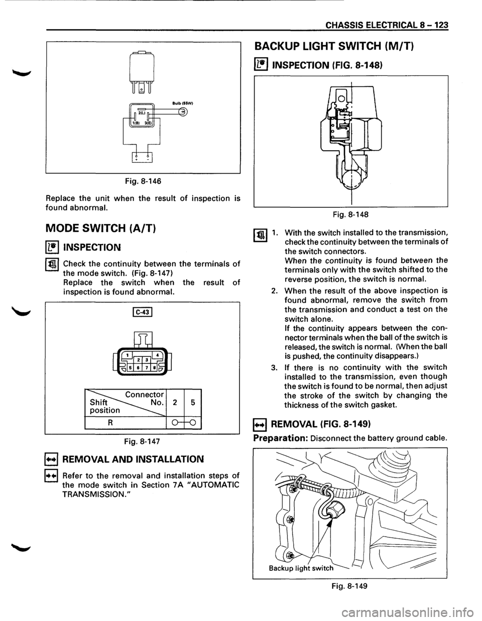
Fig. 8-146
Replace the unit when the result of inspection is
found abnormal.
MODE SWITCH (A/T)
~ INSPECTION
1~1 Check the continuity between the terminals of
the mode switch. (Fig. 8-147)
Replace the switch when the result of
inspection is found abnormal.
Fig. 8-147
B REMOVAL AND INSTALLATION
1••1 Refer to the removal and installation steps of
the mode switch in Section 7A "AUTOMATIC
TRANSMISSION."
CHASSIS ELECTRICAL 8-123
BACKUP LIGHT SWITCH (M/T)
~ INSPECTION (FIG. 8-148}
[!) 1.
Fig. 8-148
With the switch
installed to the transmission,
check the continuity between the
terminals of
the switch connectors.
When the continuity is found between the
terminals only with the switch shifted to the
reverse position, the switch
is normal.
2. When the result of the above inspection is
found abnormal, remove the switch from
the transmission and conduct a test on the
switch
alone.
If
the continuity appears between the con
nector
terminals when the ball of the switch is
released, the switch is normal. (When the ball
is pushed, the continuity disappears.)
3. If there is no continuity with the switch
installed to the transmission, even though
the switch is found to be normal, then adjust
the stroke
of the switch by changing the
thickness
of the switch gasket.
B REMOVAL (FIG. 8-149}
Preparation:
Disconnect the battery ground cable.
Fig. 8-149
Page 1314 of 1928
8-124 CHASSIS ELECTRICAL
1. Backup light switch For low note (Fig.S-151)
• Remove the connectors.
• Remove the switch by turning it counter
clockwise.
B INSTALLATION
To install, follow the removal steps in the reverse
order,
noting the following point.
1.
Backup light switch
li:i1 • Apply liquid gasket to the screw portion of
~ the switch to prevent oil leak.
BACKUP LIGHT BULB
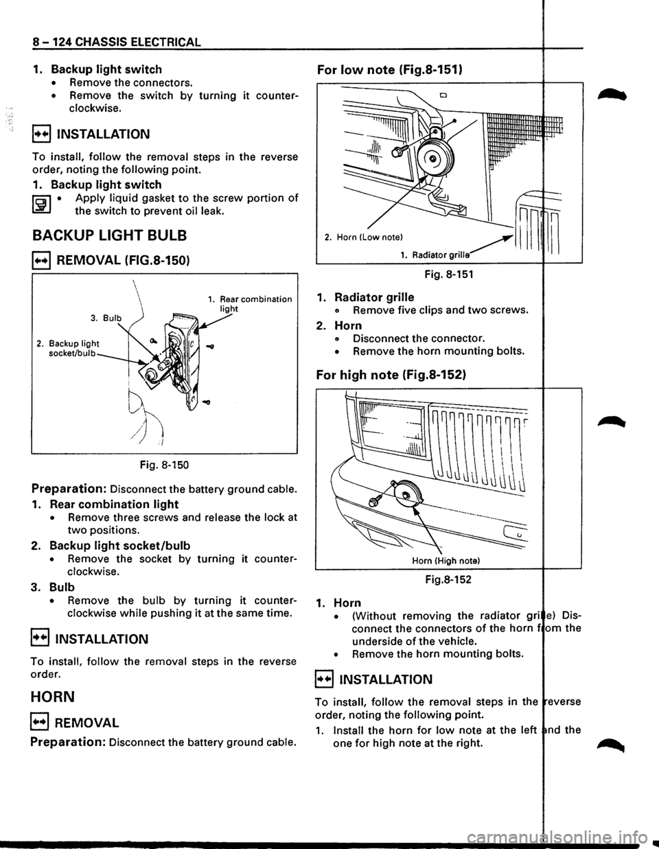
B REMOVAL (FIG.S-150)
2. Backup light
socket/bulb
i ''V
f
~h /) i/
Fig. 8-150
Preparation: Disconnect the battery ground cable.
1. Rear combination light
• Remove three screws and release the lock at
two positions.
2.
Backup light socket/bulb
• Remove the socket by turning it counter
clockwise.
3. Bulb
• Remove the bulb by turning it counter
clockwise
while pushing it at the same time.
B INSTALLATION
To install, follow the removal steps in the reverse
order.
HORN
B REMOVAL
Preparation: Disconnect the battery ground cable.
Fig. 8-151
1.
Radiator grille
o Remove five clips and two screws.
2. Horn
o Disconnect the connector.
• Remove the horn mounting bolts.
For high note (Fig.S-152)
Horn (High note)
Fig.8-152
1. Horn
• {Without removing the radiator gri e) Dis
connect the connectors of the horn f om the
underside
of the vehicle.
•
Remove the horn mounting bolts.
8 INSTALLATION
To install, follow the removal steps in the everse
order, noting the
following point.
1. Install the horn for low note at the left nd the
one
for high note at the right. ~
Page 1316 of 1928
8-126 CHASSIS ELECTRICAL
~ INSPECTION
lt!ll Check to see if there is any continuity between
the
relay terminals. (Fig. 8-156)
Replace the
relay when the result of inspection
is
found abnormal.
®-@ ....... No continuity
(When the battery voltage is applied between
CORNERING LIGHT RELAY
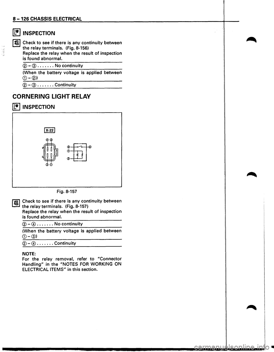
~ INSPECTION
Fig. 8-157
r1il Check to see if there is any continuity between
1.!!!.1 the relay terminals. (Fig. 8-157)
Replace the relay when the result of inspection
is
found abnormal.
®-@ ....... No continuity
(When the battery voltage is applied between
NOTE:
For the relay removal, refer to "Connector
Handling" in the "NOTES FOR WORKING ON
ELECTRICAL ITEMS" in this section.
•
Page 1318 of 1928
8-128 CHASSIS ELECTRICAL
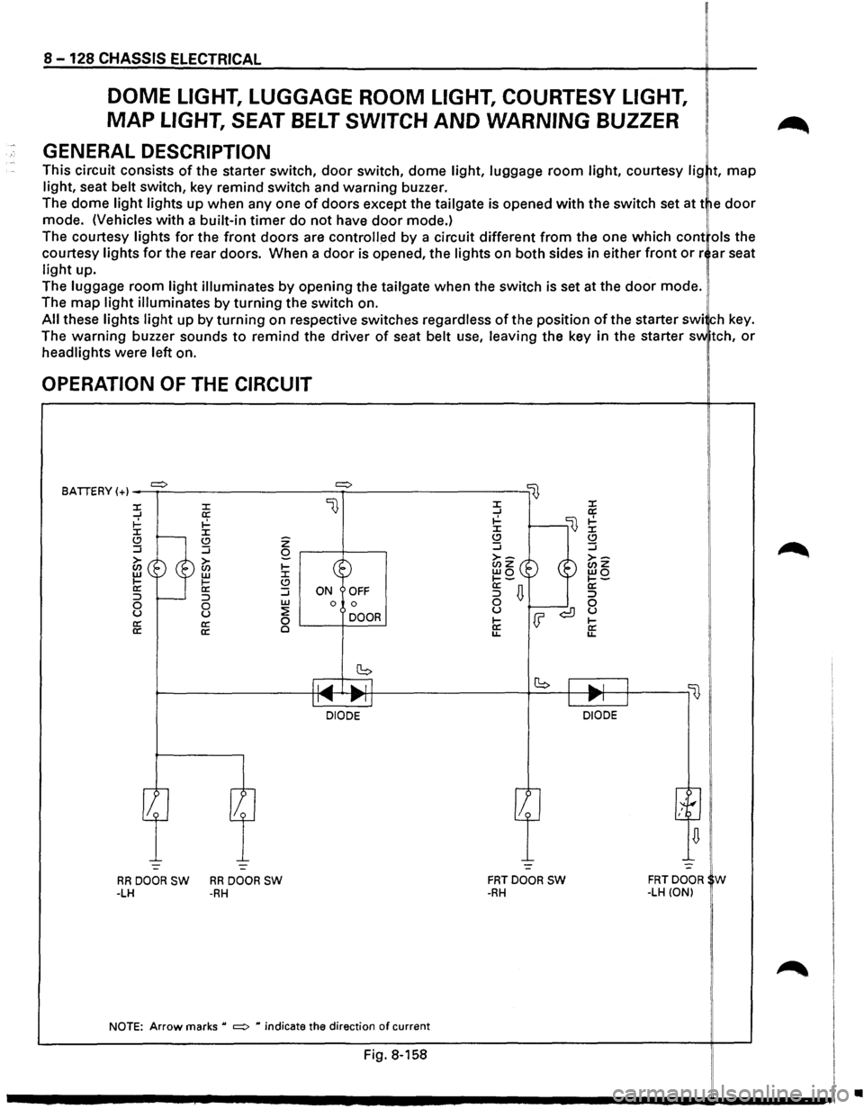
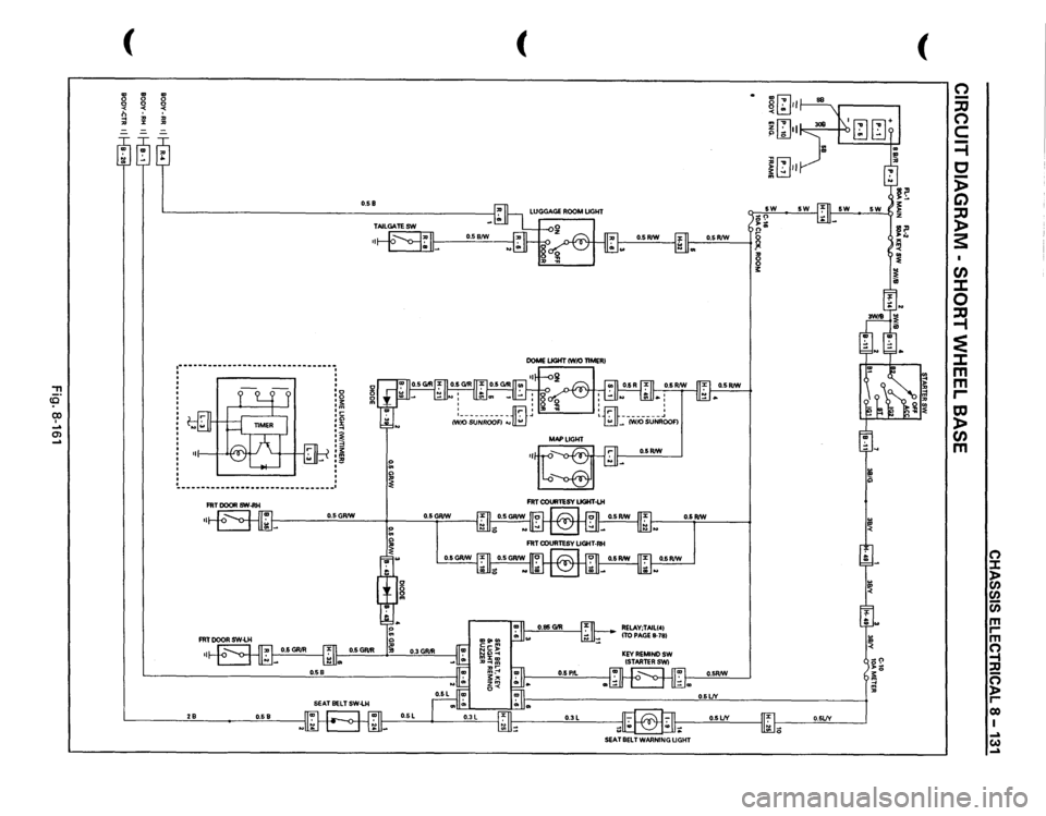
DOME LIGHT, LUGGAGE ROOM LIGHT, COURTESY LIGHT,
MAP LIGHT, SEAT BELT SWITCH AND WARNING BUZZER
GENERAL DESCRIPTION
This circuit consists of the starter switch, door switch, dome light, luggage room light, courtesy lig t, map
light, seat belt switch, key remind switch and warning buzzer.
The dome
light lights up when any one of doors except the tailgate is opened with the switch set at t e door
mode. (Vehicles with a built-in timer do not have door mode.) !
The courtesy lights for the front doors are controlled by a circuit different from the one which cont ols the
courtesy
lights for the rear doors. When a door is opened, the lights on both sides in either front or r ar seat
light up.
The
luggage room light illuminates by opening the tailgate when the switch is set at the door mode.
The
map light illuminates by turning the switch on.
All these lights light up by turning on respective switches regardless of the position of the starter swi ch key.
The
warning buzzer sounds to remind the driver of seat belt use, leaving the key in the starter sv.. tch, or
headlights were left on.
OPERATION OF THE CIRCUIT
BATIERY (+) _....,.=>..:.__ _________ =>~---------lij
l} :X: :X: ...J a: ~ ~ :X: :X: Q .....__ (.!) ...J :J
~~ ®~ II: li: :::> r----:::> 0 0 u u a: a:
a: a:
z Q r---t----,
~ Go (.!) :J w ON OFF 0 0
~ DOOR 0 '-----+------'
~----------~~~~~~~~lr-l ____________ ,_b __ +-~~~-'--~'---,~ II...... 111"""11 Ill"""' J
-:..._ -=-
RRDOORSW RRDOORSW -LH -RH
DIODE DIODE
-=
FRTDOOR SW -RH
NOTE: Arrow marks u =:> H indicate the direction of current
Fig. 8-158
FRTDOOR W -LH (ON)
•
Page 1319 of 1928
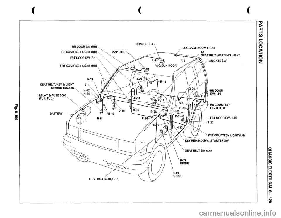
, ce· co I .... U1 co
(
RR
DOOR
SW
(RH)
, '-..__
RR
COURTESY LIGHT
(RH)
, ,
~
MAP
LIGHT~
FRT
DOOR
SW
(RH)
,
~,
~
,·
"·,.
FRT
COURTESY LIGHT (RH),
\\,
:~~ /,
' ;. >,I
H-21
(\
/~~
\,
SEAT
BELT,
KEY
&LIGHT
B-1,
REMIND BUZZER
~
""
~
H-12,""
RELAY & FUSE
BOX,
~
14
',,
(FL-1, FL-2)
'~
'
BATIERY
FUSE
BOX IC-10, C-16)
( DOME
LIGHT
/ 1 LUGGAGE
ROOM
LIGHT
1-9 SEATBELTWARNING
LIGHT
, TAILGATE
SW
/
RR
DOOR
SW(LH)
I(Y.£!
= /
I RR
COURTESY
LIGHT(LH)
~11
) I
FRT
DOOR
sw.
(LH)
-
I.
B-22
FRT
COURTESY LIGHT
(LH)
KEY
REMIND SW,
(STARTER
SW)
SEAT BELT
SW
(LH)
(
~ :lJ ~ r-0 0 ~ 0 2
0 :c 1:i en 0 m I""' m 0 -t ::0 cs )> I""' co I ...a N CD
Page 1321 of 1928
, co CX) . ... Ol ...
( --.. ..
.. 0 0 0 ~
~
0 <
!:l
,;,
,;,
"'
X
,
------------------------------~
. :g :~ ,c •"' ,x . ... :~ ·-•!: om :2!
--------------------------------·
FRT
DOOR
SW-RH
O.SGR/W
2B
O.SB
O.SB/W
~ C> ~
O.SGR/W
( ,,o.J-.r.~ FRT COURTESY
UGHT-LH
FRT
COURTESY
UGHT-RH
O.SR/W
O.SR!W
RELAV;TAILI•I ITO PAGE
8-781
KEY
REMIND
SW
CST ARTER
SW1
O.SR/W O.SR/W
O.SR/W
O.SR/W O.SlJY
8 !:
0 ., "'[;] ~ .;. ,,
mf"Yl ~liJ•Ik-
lb I ill
ill?j
~~., !~
~ :~ I h
.. !!' "'
II
O.SlJY
II~ I
O.SLJV
I
~ 0
SEAT
BELT
WARNING
LIGHT
(
(") -::0 (") c =i c 5> C) ::0 )> s I CJ) :I: 0 ~ ~ :I: m
m r-to )> CJ) m I I I
() :::t )> en
en (i) m r-m () -1 :c 0 )> r-QO I ..a w ..a
Page 1325 of 1928
EJ INSTALLATION
To install, follow the removal steps in the reverse
order.
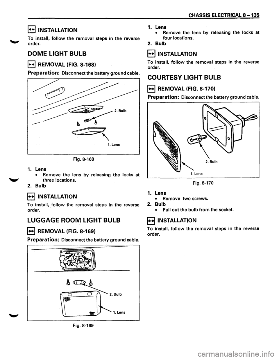
DOME LIGHT BULB
B REMOVAL (FIG. 8-168)
Preparation: Disconnect the battery ground cable.
Fig. 8-168
1. Lens
• Remove the lens by releasing the locks at
"-" three locations.
2. Bulb
B INSTALLATION
To install, follow the removal steps in the reverse
order.
LUGGAGE ROOM LIGHT BULB
B REMOVAL (FIG. 8-169)
Preparation: Disconnect the battery ground cable.
Fig. 8-169
CHASSIS ELECTRICAL 8 -135
1. Lens
• Remove the lens by releasing the locks at
four locations.
2. Bulb
B INSTALLATION
To install, follow the removal steps in the reverse
order.
COURTESY LIGHT BULB
B REMOVAL (FIG. 8-170)
Preparation: Disconnect the battery ground cable.
2. Bulb
Fig. 8-170
1. Lens
• Remove two screws.
2. Bulb
• Pull out the bulb from the socket.
E) INSTALLATION
To install, follow the removal steps in the reverse
order.
Page 1326 of 1928
8 -136 CHASSIS ELECTRICAL
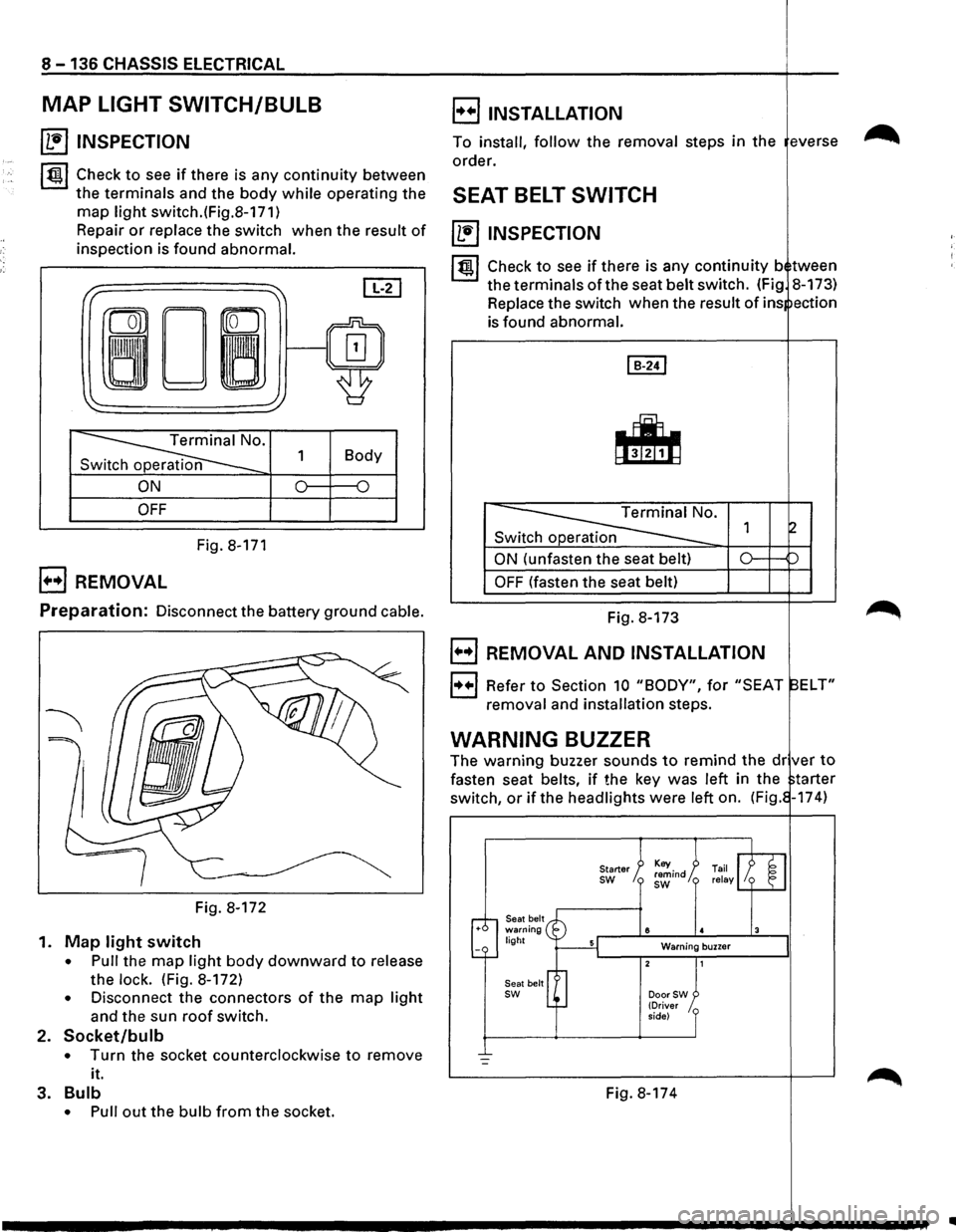
MAP LIGHT SWITCH/BULB
~ INSPECTION
~~~ Check to see if there is any continuity between
the terminals and the body while operating the
map light switch.(Fig.8-171)
Repair
or replace the switch when the result of
inspection is found abnormal.
I" ~ [IT]
ron
0~/~ ~
'
~· 1 Body
n
ON 0 {)
OFF
Fig. 8-171
B REMOVAL
E) INSTALLATION
To install, follow the removal steps in the everse
order.
SEAT BELT SWITCH
~ INSPECTION
I~ l Check to see if there is any continuity b tween
the terminals of the seat belt switch. (Fig 8-173)
Replace the switch when the
result of ins ection
is found abnormal.
Switch operation
ON (unfasten the seat belt)
OFF (fasten the seat belt)
Preparation: Disconnect the battery ground cable. Fig. 8-173
Fig. 8-172
1.
Map light switch
• Pull the map light body downward to release
the
lock. (Fig. 8-172)
• Disconnect the connectors of the map light
and the sun roof switch.
2. Socket/bulb
• Turn the socket counterclockwise to remove
it.
3.
Bulb
• Pull out the bulb from the socket.
B REMOVAL AND INSTALLATION
1++1 Refer to Section 10 "BODY", for "SEAT ELT"
removal and installation steps.
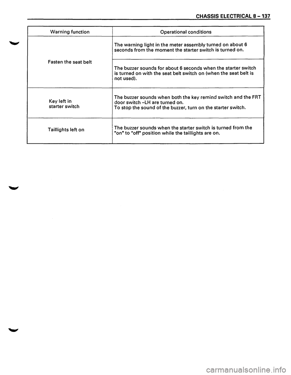
WARNING BUZZER
The warning buzzer sounds to remind the dr ver to
fasten seat belts, if the key was left in the tarter
switch,
or if the headlights were left on. (Fig. -174)
Seat belt warning light
Seat belt
sw
Starter sw
8
Warning buzzer
DoorSW (Driver
side)
Fig. 8-174
..
Page 1327 of 1928
CHASSIS ELECTRICAL 8-137
Warning function
Operational conditions
The
warning light in the meter assembly turned on about 6
seconds
from the moment the starter switch is turned on.
Fasten the seat
belt
The buzzer sounds for about 6 seconds when the starter switch
is turned on with the seat belt switch on (when the seat belt is
not used).
Key left in The
buzzer sounds when both the key remind switch and the
FRT
door switch -LH are turned on.
starter switch
To
stop the sound of the buzzer, turn on the starter switch.
Taillights left on The
buzzer sounds when the starter switch is turned
from the
"on• to "off" position while the taillights are on.
Page 1328 of 1928
8-138 CHASSIS ELECTRICAL
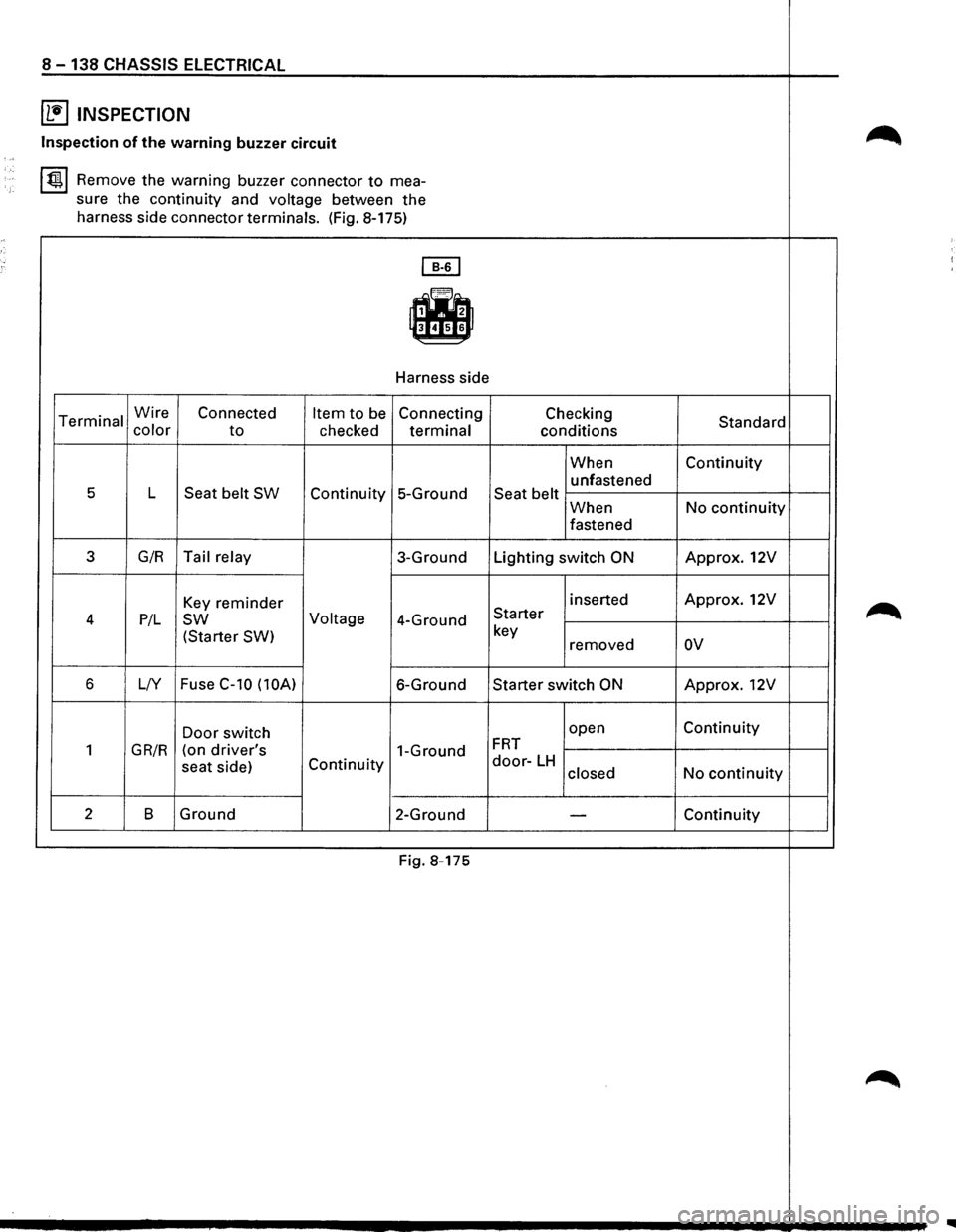
~ INSPECTION
~ Inspection of the warning buzzer circuit ,,,
~ Remove the warning buzzer connector to mea-
sure the continuity and
voltage between the
harness side connector terminals. (Fig. 8-175)
~
-Harness side
Terminal Wire Connected Item to be Connecting Checking Standard color to checked terminal conditions
When Continuity
unfastened
5 L Seat belt SW Continuity 5-Ground Seat belt When No continuity
fastened
3 G/R Tail relay 3-Ground Lighting switch ON Approx. 12V
Key reminder inserted Approx. 12V
~ 4 P/L sw Voltage 4-Ground Starter
(Starter SW)
key
removed ov
6 L/Y Fuse C-10
(lOA) 6-Ground Starter switch ON Approx. 12V
Door switch open Continuity
1 GR/R (on driver's 1-Ground FRT
seat
side) Continuity door-LH No continuity closed
2 B Ground
2-Ground -Continuity
Fig. 8-175
~