light ISUZU TROOPER 1995 Workshop Manual
[x] Cancel search | Manufacturer: ISUZU, Model Year: 1995, Model line: TROOPER, Model: ISUZU TROOPER 1995Pages: 1928
Page 1442 of 1928
8-252 CHASSIS ELECTRICAL
1. Front console assembly
2. Lower cluster assembly
3. Instrument panel driver lower cover
4. Instrument panel cluster assembly
• Refer to FOG LIGHT SWITCH removal steps in
this section.
5. Digital clock
• To remove the clock, pushing the lock from the
back side
of the cluster assembly.
E) INSTALLATION
To install, follow the removal steps in the reverse
order.
Page 1454 of 1928
8-264 CHASSIS ELECTRICAL
STARTER SWITCH
Refer to "START AND CHARGING" in this section.
DOOR MIRROR SWITCH ASSEMBLY
(CONTROL SWITCH, FOLDING
SWITCH
AND DEFOGGER SWITCH)
(FIG. 8-305)
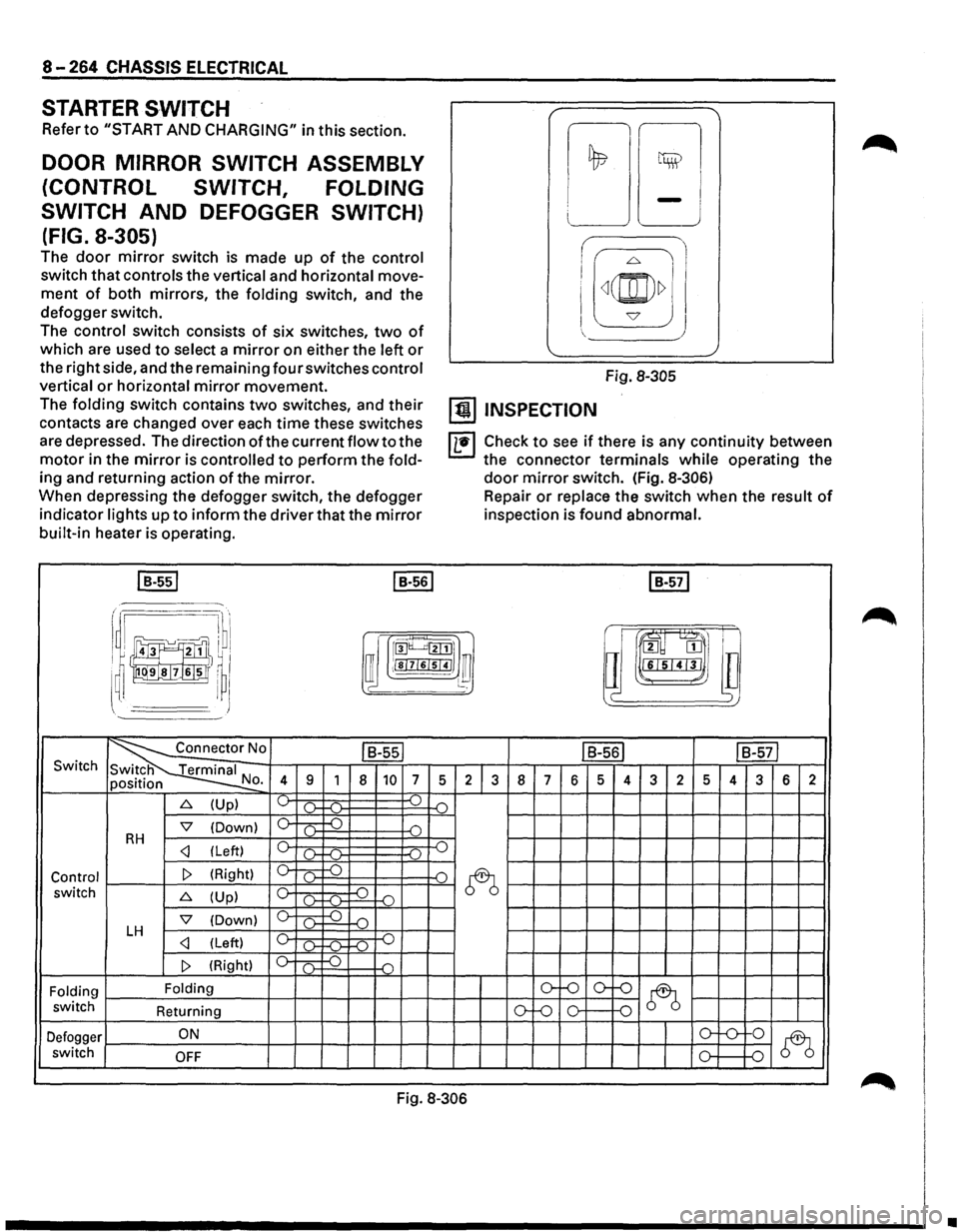
The door mirror switch is made up of the control
switch that controls the vertical and horizontal move
ment of both mirrors, the folding switch, and the
defogger switch.
The control switch consists of six switches, two of
which are used to select a mirror on either the left or
the right side, and the remaining four switches control
vertical or horizontal mirror movement.
The folding switch contains two switches, and their
contacts are changed over each time these switches
are depressed. The direction of the current flow to the
motor in the mirror is controlled to perform the fold
ing and returning action of the mirror.
When depressing the defogger switch, the defogger
indicator lights up to inform the driver that the mirror
built-in heater is operating.
I B-551 I B-561
i I I
!;l ~
LJ -J
I
I[~(@)~] J
Fig. 8-305
[!) INSPECTION
IL•I Check to see if there is any continuity between
the connector terminals while operating the
door mirror switch. (Fig. 8-306)
Repair or replace the switch when the result of
inspection is found abnormal.
I B-571
r .·~·· I ~ru·l
~~J!]}I ~ rroo~~l]
i !)~~1,1
a m
I ~ I ffi ;!sl7l6lsl41 ~ l~ lll"L•I'J'I•J ~~~
~' I J )
~0 ls-ssl IB-561 IB-571 Switch
N 4 9 1 8 10 7 5 2 3 8 7 6 5 4 3 2 5 4 3 6 2 o.
6. (Up) ~ ).. ...( ) .(")
'7 (Down) 0 c .) D RH c _.)
~ switch 6. (Up) c ~ -o ()-f-(l-
'7 (Down) 0 ( ) D LH c _.)
Folding Folding o-f-0 o--()
~ switch
Returning ()-Lo 0 0
Defogger ON o-'-0-
0
~ switch OFF 0 D
Fig. 8-306
•
Page 1460 of 1928
8-270 CHASSIS ELECTRICAL
ANTI-THEFT SYSTEM
GENERAL DESCRIPTION .......
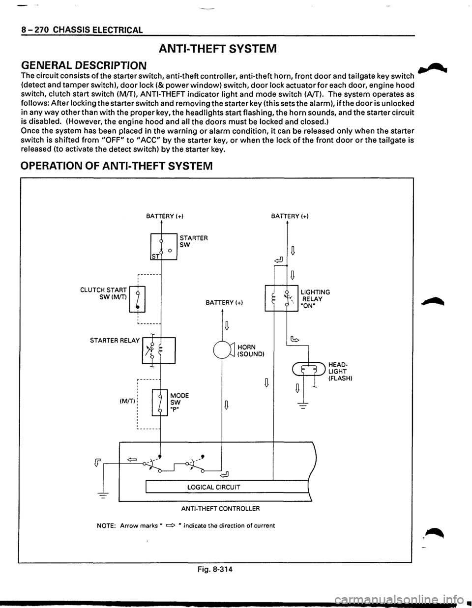
The circuit consists ofthe starter switch, anti-theft controller, anti-theft horn, front door and tailgate key switch
(detect and tamper switch),
door lock (&power window) switch, door lock actuator for each door, engine hood
switch, clutch start switch (MfT),
ANTI-THEFT indicator light and mode switch (AfT). The system operates as
follows: After locking the starter switch and removing the starter key (this sets the alarm),
ifthe door is unlocked
in any
way other than with the proper key, the headlights start flashing, the horn sounds, and the starter circuit
is disabled. (However,
the engine hood and all the doors must be locked and closed.)
Once the system has been placed in the warning or alarm condition, it can be released only when the starter
switch is shifted
from "OFF" to "ACC" by the starter key, or when the lock of the front door or the tailgate is
released (to activate the detect switch)
by the starter key.
OPERATION OF ANTI-THEFT SYSTEM
'
'
CLUTCH START m
SW(M/Tiw
' '
'
BATIERY(+)
0 ST
STARTER sw
BATIERY(+)
L------
STARTER RELAY
' ' (MIT):
'
'
'
HORN
(SOUND)
ANTI-THEFT CONTROLLER
BATIERY(+)
LIGHTING
RELAY
"ON"
HEADLIGHT (FLASH)
NOTE: Arrow marks u ~ u indicate the direction of current
Fig. 8-314
•
Page 1462 of 1928
8-:-272 CHASSIS ELECTRICAL
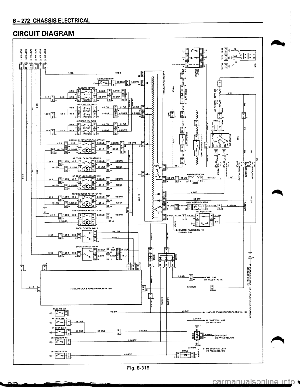
CIRCUIT DIAGRAM
3 3
3 3 3 3 !1 !1
!1 !1
!1 '< '< ~ ~ '< ;:: "' =-=-=-=-
=-
1.258 O.Rti8
5W
tl ~ ~ '" ,----.~ :j ' ~ ~1 :~
~'
~
g ~ ~ ~ ~ -~ ,p 1.258 .~
~~ ---~= ~= in ~~ >w i5 r ~ tl z g ~ .! .. ~ ?' ~ ~ ~ 1! .. 0.85G'O ~ 2 G'O 0 U!iB 1'1 1:
1.25LG/W
0.6LGIR 1.258 0.5LLIV
l.l!iB
1.258 FRT DOOR LOCK&. POWER WINDOW SW -LH 1.25LGIW
~ -~ c
~ 8 II-----------_!!,!!..!!!!..._ ________ .__-+-+---~!.ML---•LUGGAGEROOMUGHTITOPA.GE8130,13U i:
Fig.
8-316
~----
•
~_:;::_;:= ... RR COURTESV LIGHT ITO PAGE&-1301
DOME LIGHT ITOPAGES-130,1311
~
,
Page 1465 of 1928
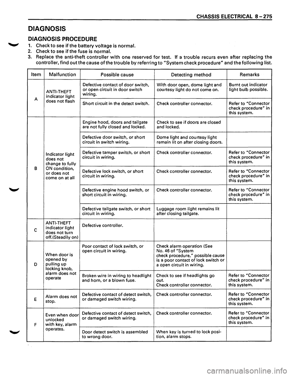
DIAGNOSIS
DIAGNOSIS PROCEDURE
.......,. 1. Check to see ifthe battery voltage is normal.
2. Check to see if the fuse is normal.
CHASSIS ELECTRICAL 8 -275
3. Replace the anti-theft controller with one reserved for test. If a trouble recurs even after replacing the
controller, find
out the cause of the trouble by referring to "System check procedure" and the following list.
Item Malfunction
Possible
cause Detecting method Remarks
Defective
contact of door switch,
With door open, dome light and Burnt
out indicator
ANTI-THEFT or open circuit in door switch courtesy light do not come on. light bulb possible.
indicator light wiring.
A does
not flash Short circuit in the detect switch.
Check controller connector. Refer to "Connector check procedure" in
this system.
Engine hood, doors and
tailgate Check to see if doors are closed are not fully closed and locked. and locked.
Defective door switch, or short Dome light and courtesy light circuit in switch wiring.
remain lit on after closing doors.
Indicator light Defective tamper switch, or short Check controller connector. Refer
to "Connector
does not circuit in wiring. check procedure" in
change to
fully this system.
B
ON condition, Defective lock switch, or short Check controller connector. Refer
to "Connector or does not come on at all circuit in wiring. check procedure" in
this system.
Defective engine hood switch, or Check
controller connector. Refer
to "Connector
short circuit in wiring. check
procedure" in
this system.
Defective
tailgate switch, or short Luggage room light remains lit circuit in wiring. after closing tailgate.
ANTI-THEFT
Defective controller.
c indicator light
does not turn off.(Steadily on) Poor contact
of lock switch, or Check alarm operation (See
When
door is open
circuit in wiring. No. 46 of "System
check procedure," possible cause
opened by
is a poor contact of lock switch or D pulling up
a open circuit in wiring. locking knob, alarm does not Broken wire in wiring to headlight Check to see if headlights go Refer
to "Connector operate
and horn, or a blown fuse. out. check procedure" in
Check
controller connector. this
system.
Alarm does not Defective contact of detect switch, Check controller connector.
Refer to "Connector
E
stop. or damaged switch wiring. check procedure" in
this system.
Even when
door Defective contact of detect switch, Check controller connector. Refer
to "Connector
unlocked
or damaged switch wiring. check procedure" in
F
with key, alarm this system.
operates. Door detect switch is
assembled When key is turned to lock posi-
to
wrong door. tion, alarm stops.
Page 1466 of 1928
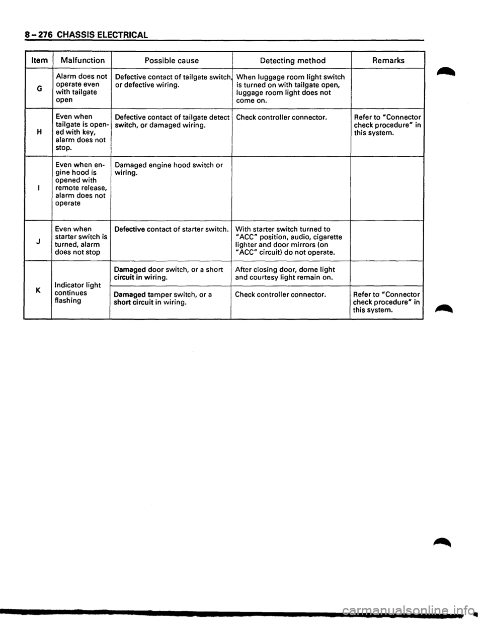
8-276 CHASSIS ELECTRICAL
Item Malfunction
Possible cause
Detecting method Remarks
Alarm
does not
Defective contact of tailgate switch When luggage room light switch
G operate even or defective wiring. is turned on with tailgate open, with tailgate
luggage room light does not open
come on.
Even when
Defective contact
of tailgate detect Check controller connector. Refer to "Connector tailgate is open-
switch, or damaged wiring.
check procedure" in H ed with key, this system.
alarm does not
stop.
Even when en-
Damaged engine hood switch or gine hood is wiring.
opened with
I remote release,
alarm does not
operate
Even when
Defective contact
of starter switch. With starter switch turned to
J starter switch is II ACC" position, audio, cigarette
turned, alarm
lighter and door mirrors (on
does not stop
II ACC" circuit) do not operate.
Damaged
door switch, or a short After closing door, dome light
circuit in wiring. and courtesy light remain on.
K Indicator light
continues Damaged tamper switch, or a
Check controller connector. Refer to "Connector flashing
short circuit in wiring. check
procedure" in
this system.
..
Page 1467 of 1928
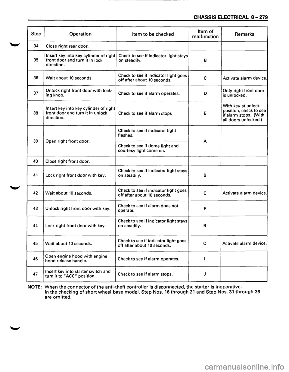
------------- -
CHASSIS ELECTRICAL 8-279
Step Operation Item to be checked Item of Remarks
malfunction
34 Close right rear door.
Insert key into key cylinder of right
Check to see if indicator light stays 35 front door and turn it in lock on steadily. B direction.
36 Wait about 10 seconds. Check
to see if indicator light goes c Activate alarm device. off after about 10 seconds.
37 Unlock right front door with lock-Check to see if alarm operates. D Only right front door ing knob.
is unlocked.
Insert
key into key cylinder of right With
key at unlock
position, check to see 38 front door and turn it in unlock Check to see if alarm stops E if alarm stops. (With
direction.
all doors unlocked.)
Check to see if indicator light flashes.
39 Open right front door.
A
Check to
see if dome light and
courtesy light come on.
40 Close right front door.
Check to
see if indicator light stays 41 Lock right front door with key.
on steadily. B
42 Wait about 10 seconds. Check
to see if indicator light goes c Activate alarm device. off after about 10 seconds.
43 Unlock right front door with key. Check
to see if alarm does not F operate.
Check to
see if indicator light stays 44 Lock right front door with key.
on steadily. B
45 Wait about 10 seconds. Check
to see if indicator light goes c Activate alarm device. off after about 10 seconds.
46 Open engine hood with engine
Check to see if alarm operates. I hood release handle.
47 Insert key into starter switch and
Check to see if alarm stops. J turn it to "ACC" position.
NOTE: When the connector of the anti-theft controller is disconnected, the starter is inoperative.
In the checking of short wheel base model, Step Nos. 16 through 21 and Step Nos. 31 through 36
are omitted.
Page 1469 of 1928
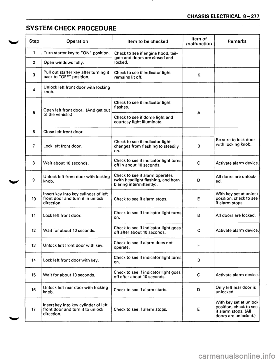
CHASSIS ELECTRICAL 8 ~ 277
SYSTEM CHECK PROCEDURE
Step Operation Item to be checked Item of Remarks malfunction
1
Turn starter key to "ON" position. Check to see if engine hood, tail-
gate and doors are closed and
2
Open windows fully. locked.
3
Pull out starter key after turning it Check to see if indicator light K back to "OFF" position.
remains lit off.
4 Unlock
left
front door with locking
knob.
Check to see if indicator light
Open left front door. (And get out flashes.
5 A
of the vehicle.) Check to see if dome light and
courtesy light illuminate.
6 Close left front door.
Check to see if indicator light Be sure to lock door
7
Lock left front door.
changes from flashing to steadily B with locking knob.
on.
8 Wait about 10 seconds. Check to see if indicator light turns c Activate alarm device. off in about 10 seconds.
Unlock left
front door with locking Check to see if alarm operates All doors are unlock-9 knob. (with
headlight flashing, and horn D ed.
blaring intermittently).
Insert key into key cylinder of left With
key set at unlock
10 front door and turn it in unlock Check to see if alarm stops. E position, check to see
direction. if alarm stops.
11 Lock left front door. Check to see if indicator light turns
B All doors are locked.
on.
12 Wait for about 10 seconds. Check to see if indicator light goes c Activate alarm device. off after about 10 seconds.
13 Unlock left front door with key. Check to see if alarm does not F
operate.
14 Lock left front door with key. Check to see if indicator light turns
B
on.
15 Wait for about 10 seconds. Check to see if indicator light goes c Activate alarm device. off after about 10 seconds.
16 Unlock left rear door with locking Check to see if alarm starts. D Only left rear door is
knob. unlocked
Insert key
into key cylinder of left With
key set at unlock
position, check to see 17 front door and turn it to unlock Check to see if alarm stops. E if alarm stops. (All direction.
doors are unlocked.)
Page 1470 of 1928
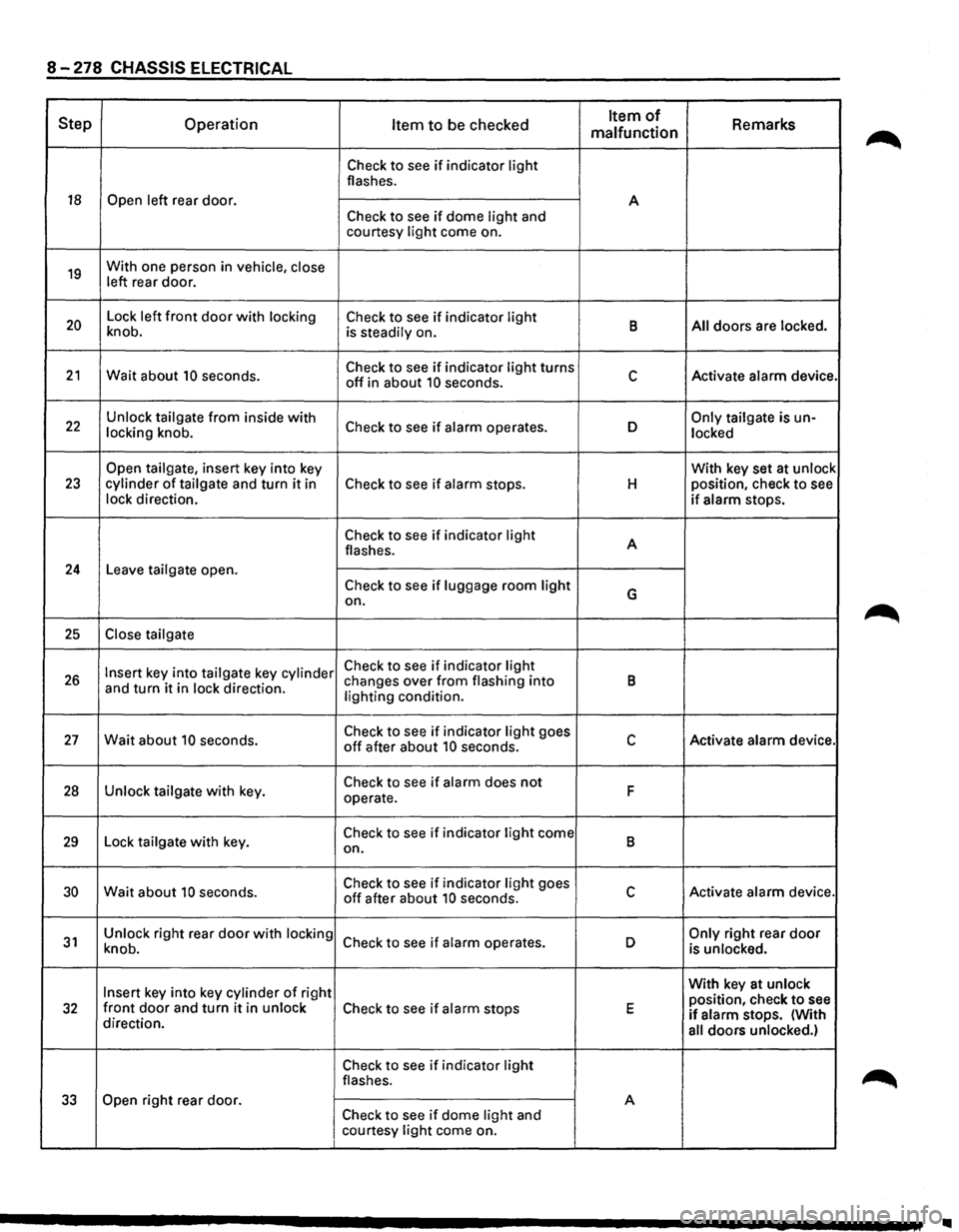
8-278 CHASSIS ELECTRICAL
Step Operation Item to be checked Item of Remarks malfunction
Check to see if indicator light flashes.
18 Open left rear door.
A
Check to see if dome light and
courtesy light come on.
19 With one person in vehicle, close
left rear door.
20 Lock left front door with locking Check to see if indicator light B All doors are locked.
knob. is steadily on.
21 Wait about 10 seconds. Check to see if indicator light turns c Activate alarm device. off in about 10 seconds.
22 Unlock tailgate from inside with Check to see if alarm operates. D Only tailgate is un-
locking knob.
locked
Open tailgate, insert key into key With key set at unlock 23 cylinder of tailgate and turn it in Check to see if alarm stops. H position,
check to see
lock direction. if alarm stops.
Check to see if indicator light A
flashes.
24 Leave tailgate open.
Check to see if luggage room light G on.
25 Close tailgate
Insert key into tailgate key cylinder Check to see if indicator light 26 and turn it in lock direction. changes
over from flashing into B lighting condition.
27 Wait about 10 seconds. Check to see if indicator light goes c Activate alarm device. off after about 10 seconds.
28 Unlock tailgate with key. Check to see if alarm does not F operate.
29 Lock tailgate with key. Check to see if indicator light come B on.
30 Wait about 10 seconds. Check to see if indicator light goes c Activate alarm device. off after about 10 seconds.
31 Unlock right rear door with locking Check to see if alarm operates.
D Only right rear door knob.
is unlocked.
Insert key into key cylinder of right With
key at unlock
position, check to see 32 front door and turn it in unlock Check to see if alarm stops E if alarm stops. (With
direction.
all doors unlocked.)
Check to see if indicator light flashes.
33 Open right rear door.
A Check to see if dome light and
courtesy light come on.
..
Page 1471 of 1928
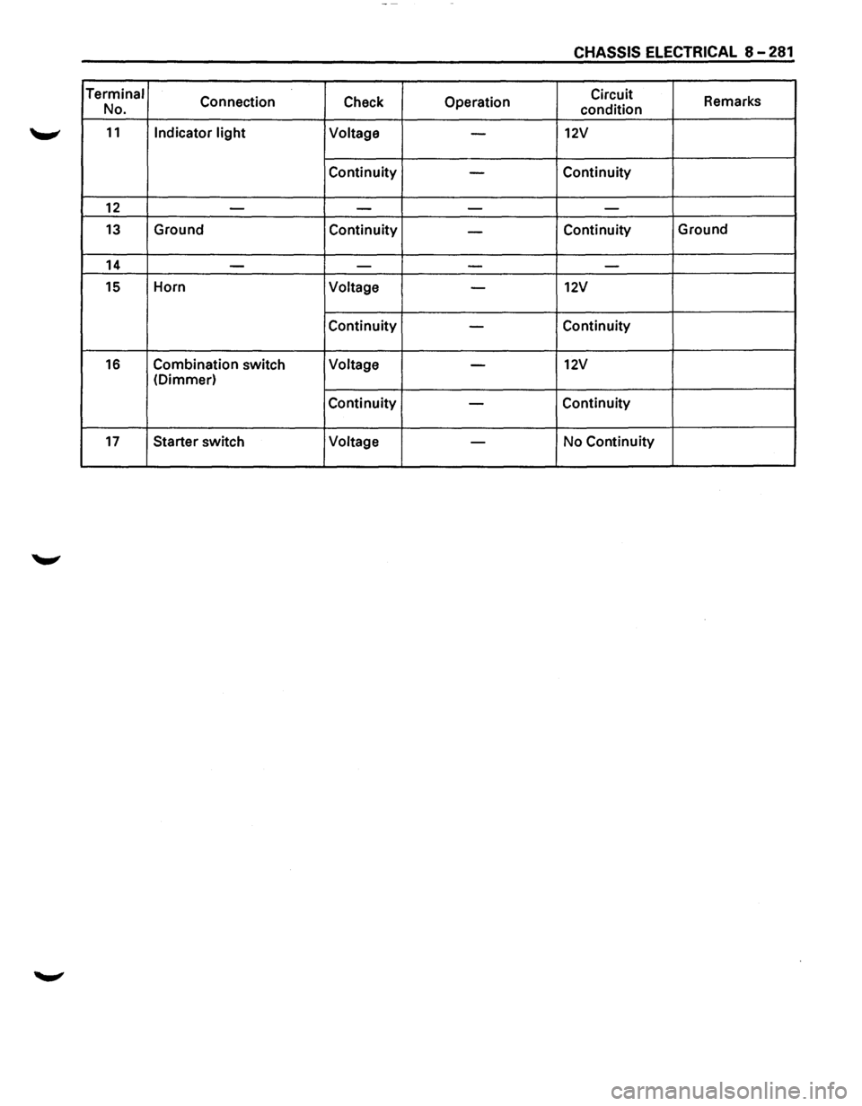
CHASSIS ELECTRICAL 8-281
Terminal
Connection Check Operation Circuit
Remarks
No. condition
11 Indicator light Voltage -12V
Continuity -Continuity
12 ----
13 Ground
Continuity -Continuity Ground
14 ---
-
15 Horn
Voltage -12V
Continuity -Continuity
16 Combination switch Voltage -12V
(Dimmer)
Continuity
-Continuity
17 Starter switch Voltage -No
Continuity