oil ISUZU TROOPER 1995 Workshop Manual
[x] Cancel search | Manufacturer: ISUZU, Model Year: 1995, Model line: TROOPER, Model: ISUZU TROOPER 1995Pages: 1928
Page 945 of 1928
AUTOMATIC TRANSMISSION (4L30-E) 7A-73
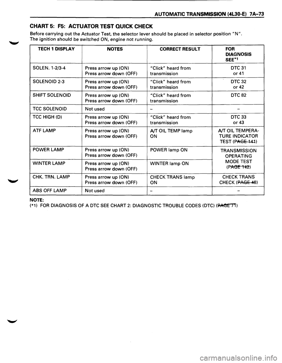
CHART 5: F5: ACTUATOR TEST QUICK CHECK
Before carrying out the Actuator Test, the selector lever should be placed in selector position "N ".
The ignition should be switched ON, engine not running.
TECH 1 DISPLAY
NOTES CORRECT RESULT FOR
DIAGNOSIS
SEE*1
SOLEN. 1-2/3-4 Press arrow up (ON)
"Click" heard from DTC31
Press
arrow down (OFF) transmission or 41
SOLENOID 2-3 Press arrow up (ON) "Click" heard from DTC 32
Press arrow down (OFF) transmission or 42
SHIFT SOLENOID Press arrow up (ON)
"Click" heard from DTC 82
Press arrow down (OFF) transmission
TCC SOLENOID Not used --
TCC HIGH (D) Press arrow up (ON)
"Click" heard from DTC33
Press
arrow down (OFF) transmission or 43
ATF LAMP Press arrow up (ON) A/TOIL TEMP lamp A/TOIL TEMPERA-
Press
arrow down (OFF) ON TURE INDICATOR
TEST (PAGE
~ 41)
POWER LAMP
Press arrow up (ON) POWER lamp ON TRANSMISSION Press arrow down (OFF) OPERATING
WINTER
LAMP Press arrow up (ON)
WINTER lamp ON MODE
TEST
Press arrow down (OFF) (P1'\(3E 1 42)
CHK. TRN. LAMP Press arrow up (ON) CHECK TRANS lamp CHECK TRANS
Press arrow down (OFF) ON CHECK (12AGE .11:8)
ABS OFF LAMP Not used - -
NOTE:
(*1) FOR DIAGNOSIS OF A DTC SEE CHART 2: DIAGNOSTIC
TROUBLE CODES (DTC) (~)
Page 952 of 1928
1 A-80 AUTOMATIC TRANSMISSION (4L30-E)
DIAGNOSTIC TROUBLE CODE (DTC) 15
TRANSMISSION OIL TEMPERATURE SHORT TO PLUS OR OPEN
This DTC does NOT flash the CHECK TRANS
indicator and does NOT set the BACKUP MODE.
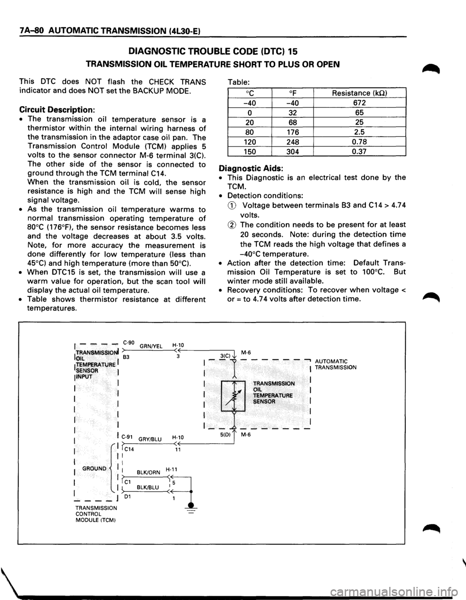
Circuit Description:
• The transmission oil temperature sensor is a
thermistor within the internal wiring harness of
the transmission in the adaptor case oil pan. The
Transmission Control Module (TCM) applies 5
volts to the sensor connector M-6 terminal 3(C).
The
other side of the sensor is connected to
ground through the TCM terminal C14.
When the transmission oil is cold, the sensor
resistance is high and the TCM will sense high
signal voltage.
• As the transmission oil temperature warms to
normal transmission operating temperature of
80°C (176°F), the sensor resistance becomes less
and
the voltage decreases at about 3.5 volts.
Note,
for more accuracy the measurement is
done differently for low temperature (less than
45°C) and high temperature (more than 50°C).
•
When DTC15 is set, the transmission will use a
warm value for operation, but the scan tool will
display the actual oil temperature.
• Table shows thermistor resistance at different
temperatures.
Table:
oc OF Resistance (kQ)
-40 -40 672
0 32 65
20 68 25
80 176
2.5
120 248 0.78
150 304 0.37
Diagnostic Aids:
• This Diagnostic is an electrical test done by the
TCM.
• Detection conditions:
CD Voltage between terminals B3 and C14 > 4.74
volts.
@ The condition needs to be present for at least
20 seconds. Note: during the detection time
the TCM reads the high voltage that defines a
-40°C temperature.
• Action after the detection time: Default Trans
mission Oil Temperature is set to 100°C. But
winter mode still available.
• Recovery conditions: To recover when voltage <
or= to 4.74 volts after detection time.
f - ---C-90 GRN/YEL H-10 ITRANSMISSIONI >---'----<•((,--------3-(C--,) I M-6 to,,IL ~ 3 ~
ltEMf!EAATURE I I --1---- ---, AUTOMATIC
SENSOR I I I TRANSMISSION
llNPUT
I
I I
I TRANSMISSION L.... Oil I
I I I ~ TEMPERATURE
I I I / SENSOR I
I I I I
r I I __ _. _______ I
I I C-91 H-10 5(0) 1' M-6 GRY/BLU I ,. I >>---_:__--< < I IC14 11
I II
II I GROUND
I BLK/ORN H-11
1 1?c1 ~q I '-. I ~>--B_L__cKI_BL_U--<~ 5
----J 01
1
TRANSMISSION
CONTROL
MODULE ITCM)
Page 953 of 1928
AUTOMATIC TRANSMISSION (4L30-E) 7 A-81
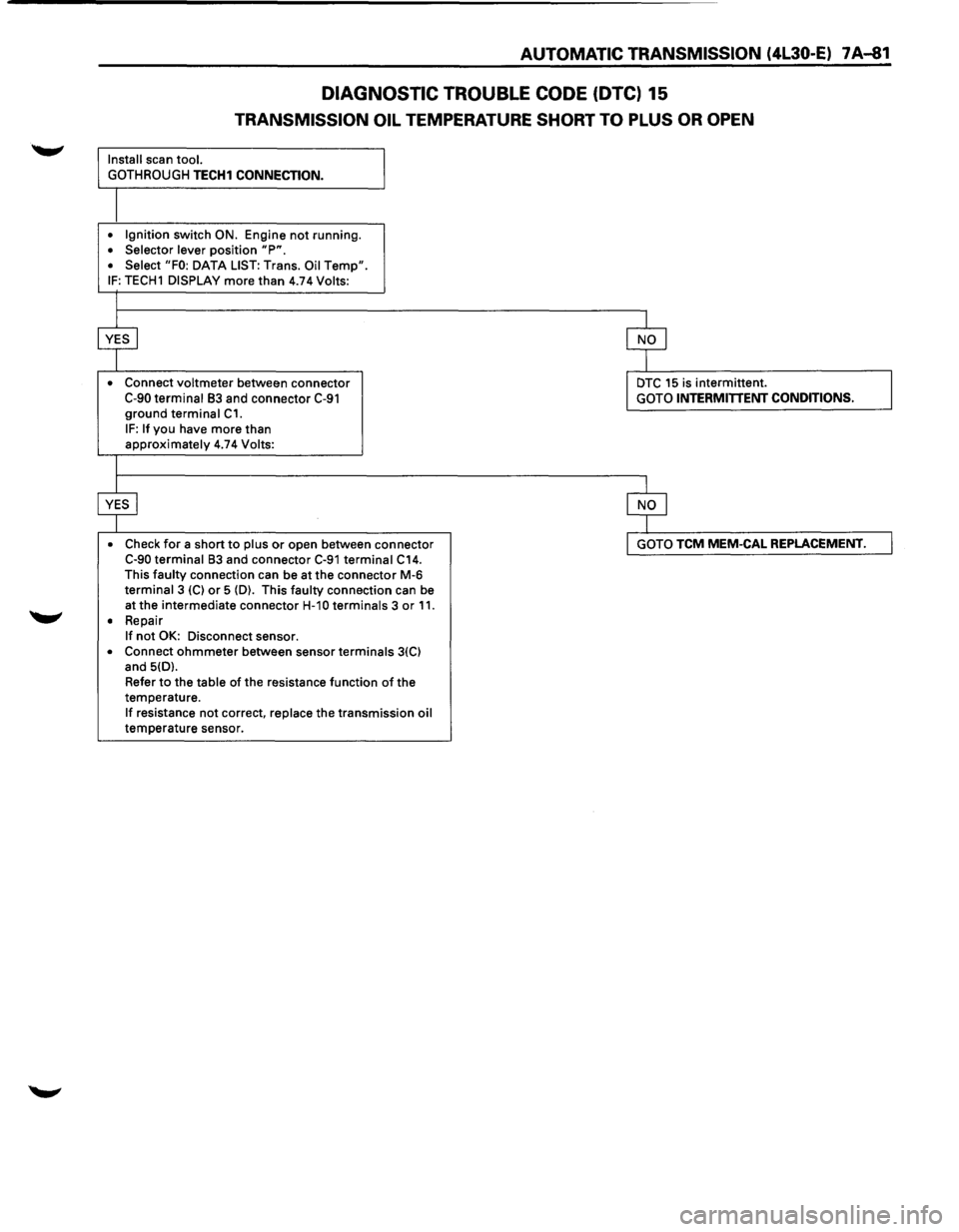
DIAGNOSTIC TROUBLE CODE (DTC) 15
TRANSMISSION OIL TEMPERATURE SHORT TO PLUS OR OPEN
Install scan tool.
GOTHROUGH
TECH1 CONNECTION.
• Ignition switch ON. Engine not running. • Selector lever position "P". • Select "FO: DATA LIST: Trans. Oil Temp". IF: TECH1 DISPLAY more than 4.74 Volts:
•
Connect voltmeter between connector C-90 terminal 83 and connector C-91 ground terminal C1.
IF: If you have more than approximately 4.74 Volts:
• Check
for a short to plus or open between connector C-90 terminal 83 and connector C-91 terminal C14. This faulty connection can be at the connector M-6 terminal 3 (C) or 5 (D). This faulty connection can be
at the intermediate connector
H-1 0 terminals 3 or 11. • Repair If not OK: Disconnect sensor.
• Connect ohmmeter between sensor terminals 3(C) and 5(D).
Refer
to the table of the resistance function of the
temperature.
If resistance not correct, replace the transmission oil temperature sensor.
DTC 15 is intermittent. GOTO INTERMITTENT CONDITIONS.
GOTO TCM MEM-CAL REPLACEMENT.
Page 954 of 1928
7 A-82 AUTOMATIC TRANSMISSION (4L30-E)
DIAGNOSTIC TROUBLE CODE (DTC) 16
TRANSMISSION OIL TEMPERATURE SHORT TO GROUND
This DTC does NOT flash the CHECK TRANS
indicator and does NOT set the BACKUP MODE.
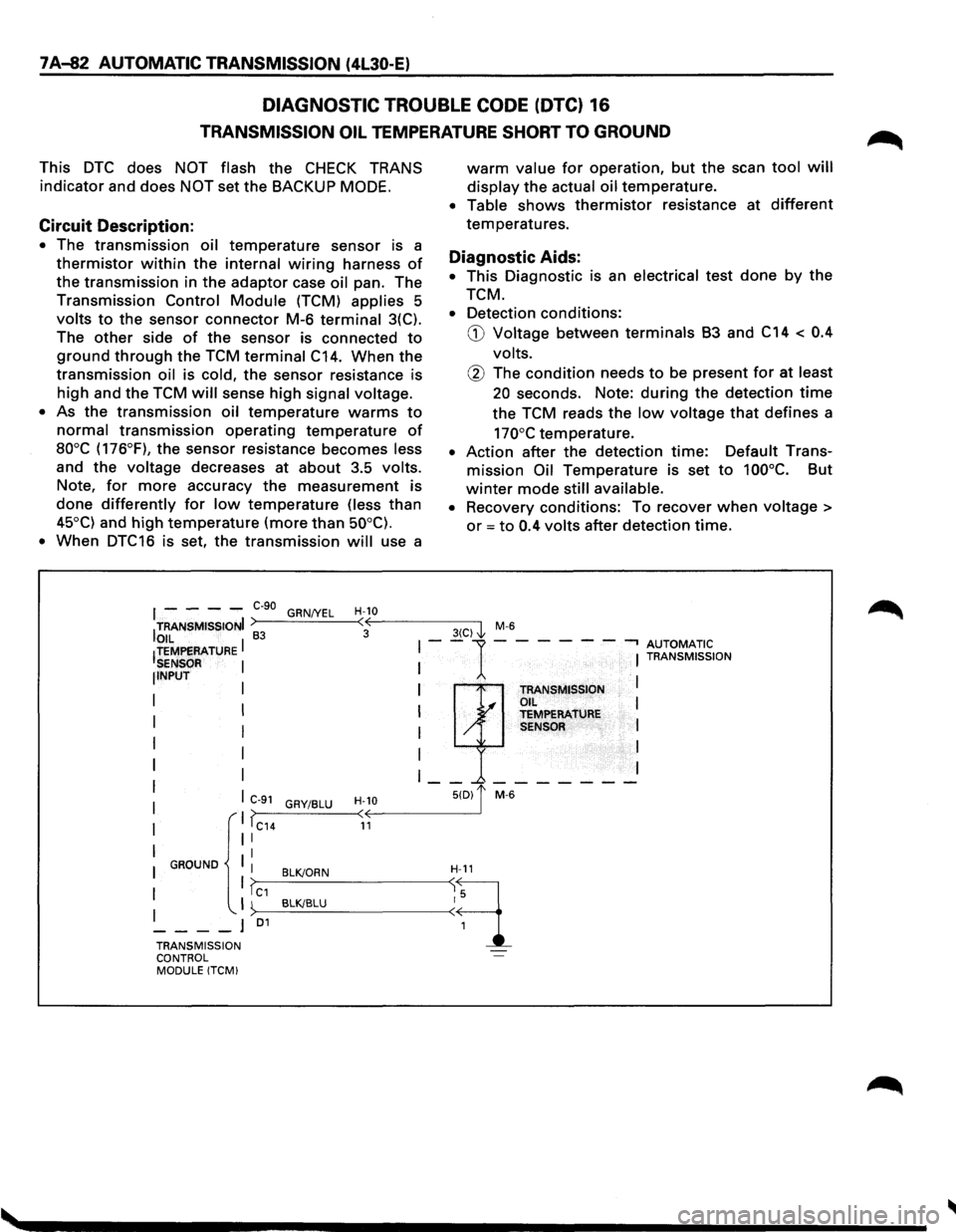
Circuit Description:
• The transmission oil temperature sensor is a
thermistor within the internal wiring harness of
the transmission in the adaptor case oil pan. The
Transmission Control Module (TCM) applies 5
volts to the sensor connector M-6 terminal 3(C).
The
other side of the sensor is connected to
ground through the TCM terminal C14. When the
transmission oil is cold, the sensor resistance is
high and the TCM will sense high signal voltage.
•
As the transmission oil temperature warms to
normal transmission operating temperature of
aooc (176°F), the sensor resistance becomes less
and the voltage decreases at about 3.5 volts.
Note, for more accuracy the measurement is
done differently for low temperature (less than
45°C) and high temperature (more than 50°C).
•
When DTC16 is set, the transmission will use a
warm value for operation, but the scan tool will
display the actual oil temperature.
• Table shows thermistor resistance at different
temperatures.
Diagnostic Aids:
• This Diagnostic is an electrical test done by the
TCM.
• Detection conditions:
G) Voltage between terminals B3 and C14 < 0.4
volts.
@ The condition needs to be present for at least
20 seconds. Note: during the detection time
the TCM reads the low voltage that defines a
170°C temperature.
• Action after the detection time: Default Trans
mission Oil Temperature is set to 100°C. But
winter mode still available.
•
Recovery conditions: To recover when voltage >
or = to 0.4 volts after detection time.
I - - - -e-go GRN/YEL H-10
ITRANSMISSIONI >----'-----<:·oE---------3-(C-)-,'1 M-6
OIL I 83 I--1-- --- -.., AUTOMATIC !TEMPERATURE I I TRANSMISSION SENSOR NPUT I TRANSMISSION I .I OIL I I y TEMPERATURE I / SENSOR I
I
I I
I __ _.-------
C>--9_1_G_RY_I_BL_U_-
TRANSMISSION ~·· ... -l
CONTROL MODULE !TCM)
Page 955 of 1928
AUTOMATIC TRANSMISSION (4L30-E) 7 A-83
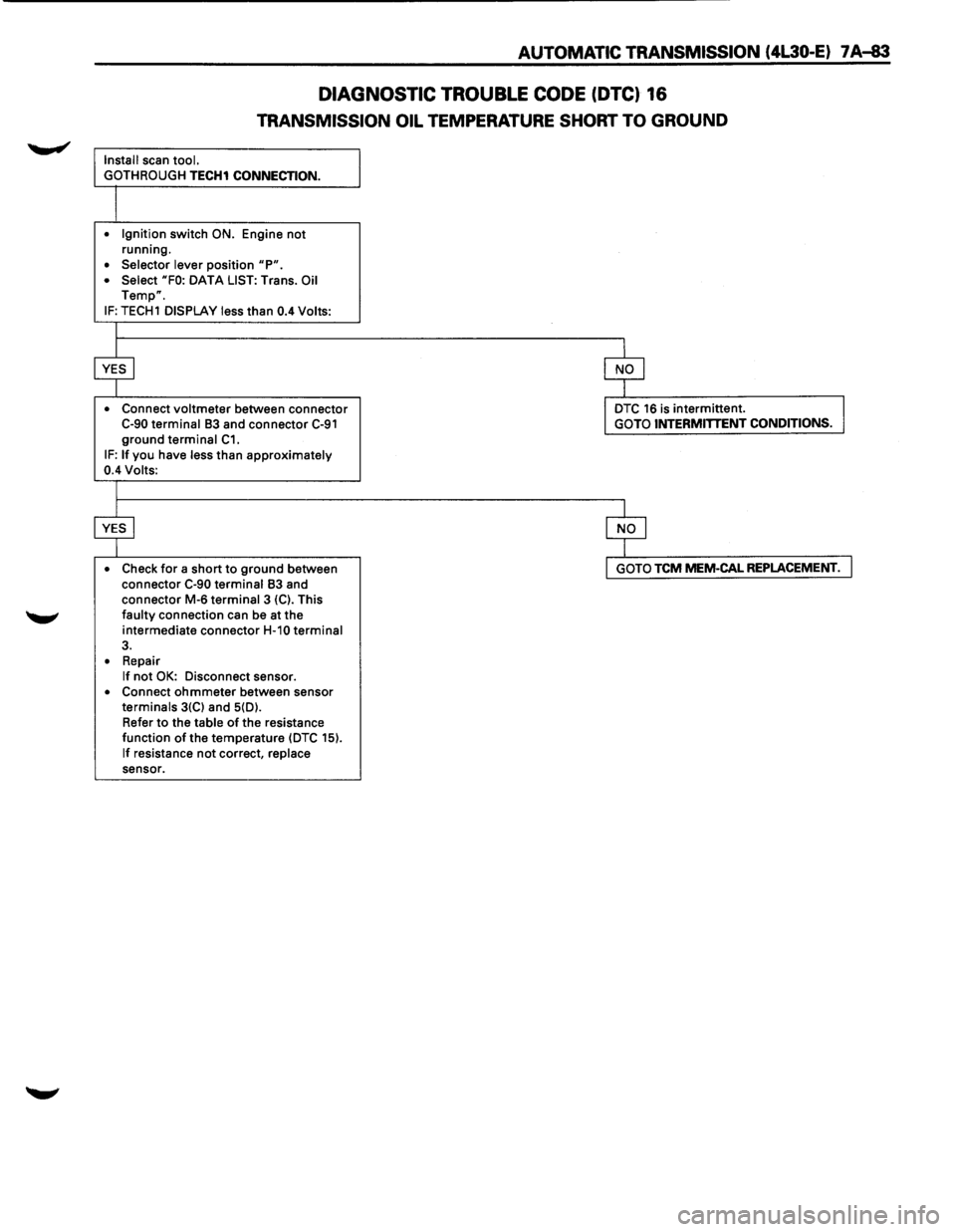
DIAGNOSTIC TROUBLE CODE (DTC) 16
TRANSMISSION OIL TEMPERATURE SHORT TO GROUND
Install scan tool.
GOTH ROUGH
TECH1 CONNECTION.
• Ignition switch ON. Engine not running.
• Selector lever position "P". • Select "FO: DATA LIST: Trans. Oil Temp".
IF: TECH1 DISPLAY less than 0.4 Volts:
• Connect
voltmeter between connector C-90 terminal 83 and connector C-91 ground terminal C1. IF: If you have less than approximately 0.4 Volts:
• Check
for a short to ground between
connector C-90 terminal 83 and
connector M-6 terminal 3 {C). This faulty connection can be at the
intermediate connector
H-10 terminal 3.
• Repair If not OK: Disconnect sensor. • Connect ohmmeter between sensor terminals 3{C) and 5{D).
Refer
to the table of the resistance
function of the temperature {DTC 15).
If resistance not correct, replace sensor.
DTC 16 is intermittent. GOTO INTERMITTENT CONDITIONS.
GOTO TCM MEM-CAL REPLACEMENT.
Page 962 of 1928
7 A-90 AUTOMATIC TRANSMISSION (4L30-E)
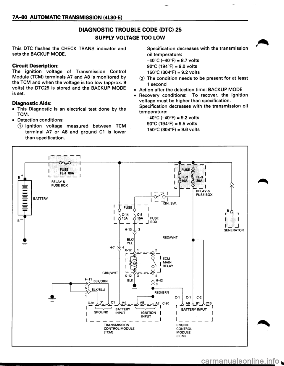
DIAGNOSTIC TROUBLE CODE (DTC) 25
SUPPLY VOLTAGE TOO LOW
This DTC flashes the CHECK TRANS indicator and
sets the BACKUP
MODE.
Specification decreases with the transmission
oil temperature:
Circuit Description:
-40°C (-40°F) = S.7 volts
90°C (194°F) = 9.0 volts
150°C (304°F) = 9.2 volts The ignition voltage of Transmission Control
Module (TCM) terminals A7 and AS is monitored by
the TCM and when the voltage is too low (approx. 9
volts) the DTC25 is stored and the BACKUP MODE
is set.
@ The condition needs to be present for at least
1 second
• Action after the detection time: BACKUP MODE
Diagnostic Aids:
• This Diagnostic is an electrical test done by the
TCM.
• Recovery conditions: To recover, the ignition
voltage must be higher than specification.
Specification decreases
with the transmission oil
temperature:
-40°C (-40°F) = 9.2 volts
90°C (194°F) = 9.5 volts
150°C (304°F) = 9.6 volts
• Detection conditions:
CD Ignition voltage measured between TCM
terminal A7 or AS and ground C1 is lower
than specification .
. · fU I
I '
f:L;~soA L., ____ J
RELAY & FUSE BOX
1--, {)-:,.--____..J BATTERY
l
T
L __ I
r
I C-14 C-8 I I 15A 15A FUSE -__ + _ j BOX
H-13t 3
H-7 'x~.~~'---7 r ]_-
GRN/WHT
BATTERY I GROUND INPUT IGNITION I INPUT I
L-----------TRANSMISSION
CONTROL MODULE
(TCM) IGN.SW.
RED/WHT
C-1 C-1 C-2
A6 B1 C16
r -;ATTERV INPUT-l
I
I l _____ j
ENGINE
CONTROL MODULE
(ECM)
I I
I-_j GENERATOR
Page 974 of 1928
7A-102 AUTOMATIC TRANSMISSION (4L30-E)
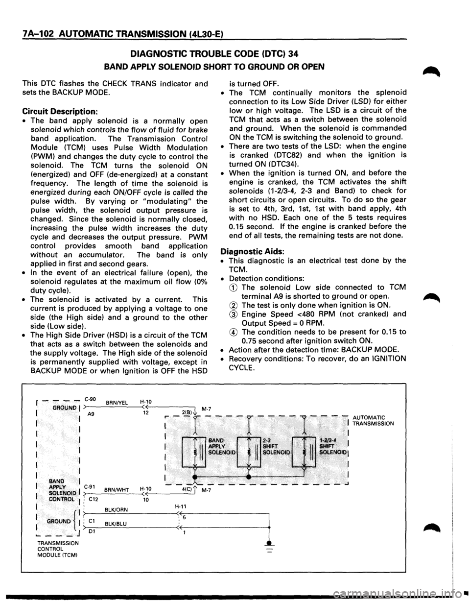
DIAGNOSTIC TROUBLE CODE
(DTC) 34
BAND APPLY SOLENOID SHORT TO GROUND OR OPEN
This DTC flashes the CHECK TRANS indicator and
sets the BACKUP
MODE.
Circuit Description:
• The band apply solenoid is a normally open
solenoid
which controls the flow of fluid for brake
band
application. The Transmission Control
Module (TCM) uses Pulse Width Modulation
(PWM) and changes the duty cycle to control the
solenoid. The
TCM turns the solenoid ON
(energized) and OFF (de-energized) at a constant
frequency. The length
of time the solenoid is
energized
during each ON/OFF cycle is called the
pulse
width. By varying or "modulating" the
pulse
width, the solenoid output pressure is
changed.
Since the solenoid is normally closed,
increasing the pulse width increases the duty
cycle and decreases the output pressure. PWM
control provides smooth band application
without an accumulator. The band is only
applied in first and second gears.
• In the event of an electrical failure (open), the
solenoid regulates at the
maximum oil flow (0%
duty cycle).
• The solenoid is activated by a current. This
current is produced
by applying a voltage to one
side (the High side) and a
ground to the other
side (low side).
• The High Side Driver (HSD) is a circuit of the TCM
that acts as a switch between the solenoids and
the
supply voltage. The High side of the solenoid
is
permanently supplied with voltage, except in
BACKUP
MODE or when Ignition is OFF the HSD
2{8)\l, M-7
r----C-90 BRN/YEL H-10 ( 12
is turned OFF.
• The TCM continually monitors the splenoid
connection
to its low Side Driver (LSD) for either
low or high voltage. The LSD is a circuit of the
TCM that acts as a switch between the solenoid
and
ground. When the solenoid is commanded
ON the TCM is switching the solenoid to ground.
• There are two tests of the LSD: when the engine
is cranked (DTC82) and
when the ignition is
turned ON (DTC34).
• When the ignition is turned ON, and before the
engine is cranked, the TCM activates the shift
solenoids (1-2/3-4, 2-3 and Band) to check for
short circuits or open circuits. To do so the gear
is set
to 4th, 3rd, 1st, 1st with band apply, 4th
with no HSD. Each one of the 5 tests requires
0.15 second. If the engine is cranked before the
end
of all tests, the remaining tests are not done.
Diagnostic Aids:
• This diagnostic is an electrical test done by the
TCM.
• Detection conditions:
CD The solenoid low side connected to TCM
terminal A9 is shorted to ground or open.
@ The test is only done when ignition is ON.
@ Engine Speed <480 RPM (not cranked) and
Output Speed= 0 RPM.
® The condition needs to be present for 0.15 to
0.75 second after ignition switch ON.
•
Action after the detection time: BACKUP MODE.
•
Recovery conditions: To recover, do an IGNITION
CYCLE.
: --r ----r ----
1-
- -: ~Z[;'~,~~ION
I 1'•1 ~~ If ~!FT . i '· !:
I
I
I
1 ·. SOI:!Noto· R sOLI!lQI,~, . ~ , ~. sOt.ENOiti•J
I ,Ji'Ji ·
· I
I •• ) . I
--~~---------~---~ >--------<
I
I I
BAND APPLY C-91 BRNtWHT H-10
I SOLENOID ( CONTROL : C12 10
I .
: GROUND {
. BLK/ORN . ; C1 BLK/BLU :> 01 ..... ---J
H-11
TRANSMISSION
CONTROL
MODULE (TCM)
•
Page 988 of 1928
7A-116 AUTOMATIC TRANSMISSION (4L30-E)
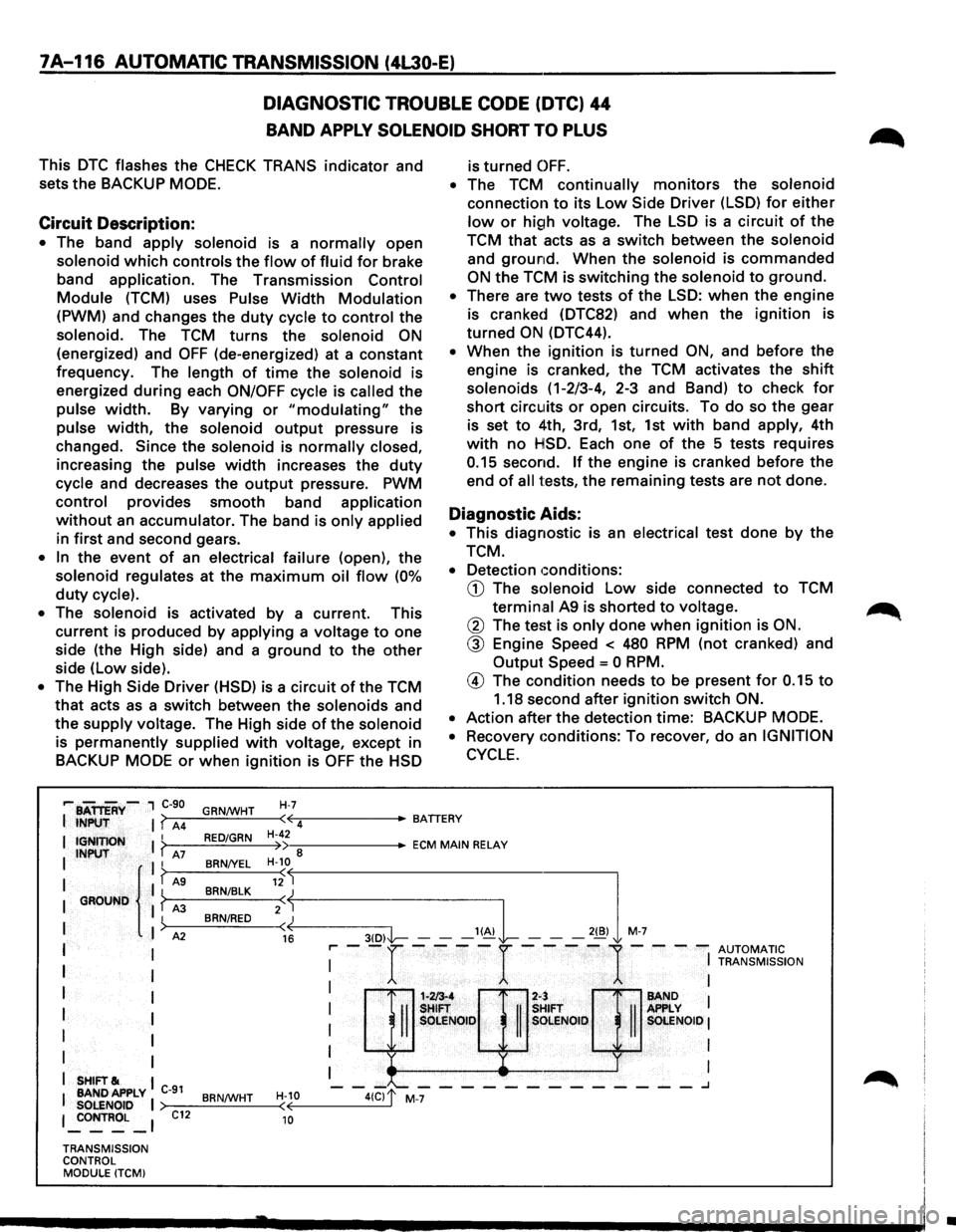
DIAGNOSTIC TROUBLE CODE (DTC) 44
BAND APPLY SOLENOID SHORT TO PLUS
This DTC flashes the CHECK TRANS indicator and
sets the BACKUP
MODE.
Circuit Description:
• The band apply solenoid is a normally open
solenoid which controls the flow of fluid for brake
band
application. The Transmission Control
Module (TCM) uses Pulse Width Modulation
(PWM) and changes the duty cycle to control the
solenoid. The TCM turns the solenoid ON
(energized) and OFF (de-energized) at a constant
frequency. The
length of time the solenoid is
energized
during each ON/OFF cycle is called the
pulse width. By varying or "modulating" the
pulse width, the solenoid output pressure is
changed.
Since the solenoid is normally closed,
increasing the pulse width increases the duty
cycle and decreases the output pressure. PWM
control provides smooth band application
without an accumulator. The band is only applied
in first and second gears.
• In the event of an electrical failure (open), the
solenoid regulates at the maximum oil flow (0%
duty cycle).
•
The solenoid is activated by a current. This
current is produced by
applying a voltage to one
side (the High side) and a
ground to the other
side (low side).
• The High Side Driver (HSD) is a circuit of the TCM
that acts as a switch between the solenoids and
the
supply voltage. The High side of the solenoid
is permanently supplied with voltage, except in
BACKUP
MODE or when ignition is OFF the HSD
H-7
is turned OFF.
• The TCM continually monitors the solenoid
connection to its Low Side Driver (LSD) for either
low or high voltage. The LSD is a circuit of the
TCM
that acts as a switch between the solenoid
and ground. When the solenoid is commanded
ON the TCM is switching the solenoid to ground.
• There are two tests of the LSD: when the engine
is cranked (DTC82) and
when the ignition is
turned
ON (DTC44).
• When the ignition is turned ON, and before the
engine is cranked, the TCM activates the
shift
solenoids (1-2/3-4, 2-3 and Band) to check for
short circuits or open circuits. To do so the gear
is set
to 4th, 3rd, 1st, 1st with band apply, 4th
with no HSD. Each one of the 5 tests requires
0.15 second. If the engine is cranked before the
end
of all tests, the remaining tests are not done.
Diagnostic Aids:
• This diagnostic is an electrical test done by the
TCM.
• Detection conditions:
CD The solenoid Low side connected to TCM
termin.al A9 is shorted to voltage.
@ The test is only done when ignition is ON.
@ Engine Speed < 480 RPM (not cranked) and
Output
Speed = 0 RPM.
@ The condition needs to be present for 0.15 to
1.18 second after ignition switch ON.
•
Action after the detection time: BACKUP MODE.
•
Recovery conditions: To recover, do an IGNITION
CYCLE.
,... BATTERY-, C-90
I INPUT I? A4 GRN/WHT ·~-----BATTERY
( 4
I IGNITION I ? I INPUT A7 II
I { I? AS I GROUND I ? A3
I
)
I A2
I I
I
I
I I
I I
I
I
I I
I SHIFT& I
I BANDAPPLY C-91 SOLENOID I 1 _:oNTROL _ 1
TRANSMISSION
CONTROL MODULE (TCMI
C12
RED/GRN
BRN/YEL
BRN/BLK
BRN/RED
BRN/WHT
H-42 •--::------ECM MAIN RELAY )) 8 H-10
«--------3-(D--,I'l----- --'~L -,,,l M-7
( 12
2:j
16 r-- -r ----r ----
1-- --
AUTOMATIC I
I TRANSMISSION
: H::Q]:;& : I OLE SOlENOID I
I I
I I
1-213-4 2-:
-II
SHIFT
II
s SOLE NOlO s
-"--------_______ .J
H-10 ( 10
•
Page 992 of 1928
7A-120 AUTOMATIC TRANSMISSION (4L30-E)
DIAGNOSTIC
TROUBLE CODE (DTC) 51
ENGINE COOLANT SWITCH SHORT TO GROUND, PLUS OR OPEN
This DTC does NOT flash the CHECK TRANS
indicator and does NOT set the BACKUP MODE.
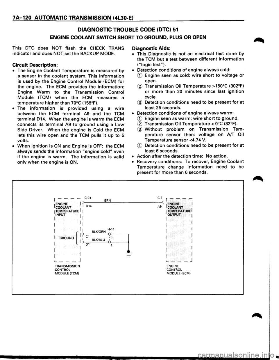
Circuit Description:
• The Engine Coolant Temperature is measured by
a sensor in the coolant system. This information
is used by the Engine Control Module (ECM) for
the engine. The ECM provides the information:
Engine Warm to the Transmission Control
Module (TCM) when the ECM measures a
temperature
higher than 70°C (158°F).
• The information is provided using a wire
between the ECM terminal A9 and the TCM
terminal D14. When the engine is warm the ECM
connects its terminal A9 to ground using a Low
Side Driver. When the engine is Cold the ECM
lets this wire open and the TCM pulls it up to 5
volts.
•
When Ignition is ON and Engine is OFF: the ECM
always sends the information "engine cold" even
if the engine is warm. The information is valid
only when the engine is ON.
Diagnostic Aids:
• This Diagnostic is not an electrical test done by
the TCM but a test between different information
("logic test").
• Detection conditions of engine always cold:
CD Engine! seen as cold: wire short to voltage or
open.
@ Transmission Oil Temperature >150°C (302°F)
or more than 20 minutes since last ignition
cycle.
@ Detection conditions need to be present for at
least 25 seconds.
• Detection conditions of engine always warm:
CD Engine! seen as warm: wire short to ground.
@ Transmission Oil Temperature< ooc (32°F).
@ Without problem on Transmission Tem
perature sensor then:
voltage on AfT Oil
Temperature sensor <4.74 V.
@ Detection conditions need to be present for at
least 6 seconds.
• Action after the detection time: No action.
• Recovery conditions: To recover, Engine Coolant
Temperature change information need to be
present
for more than 6 seconds.
r - - - -C·91 BRN C-1 r - - - -
I ~~~ENT I f,_D_1_4 __ ~.!__--------~-: I ~NGt~~ I
1 teMPERAtuRE I 1
1 t=R'ATJJRel
I INPUT I I I OUTP\:IT l
I 1
1 I I
I I I H-11 I l
I
GROUND 11 ? C1 BLKJORN ~9 I I I I BLKJBLU ( 1 I > o1 I
I I 1 I I
I I I I
~---J ~---J TRANSMISSION ENGINE
CONTROL CONTROL
MODULE
(TCM) MODULE (ECM)
•
Page 1012 of 1928
7A-140 AUTOMATIC TRANSMISSION (4L30-E)
WITHOUT DTC SET
1. If you have already checked the Diagnostic
Trouble Code (DTC) and the scan tool TECH1
does not provide any DTC, and you have
reproduced the
problem and no DTC was
stored:
This means that you have
to check the problem
by comparing the way it should work to the
way it works now that the problem exits.
2. To find the problem, perform the following
tests:
• A/TOil Temperature Indicator Test
• Transmission Operating Mode Test
•