oil ISUZU TROOPER 1995 Workshop Manual
[x] Cancel search | Manufacturer: ISUZU, Model Year: 1995, Model line: TROOPER, Model: ISUZU TROOPER 1995Pages: 1928
Page 1063 of 1928
~
AUTOMATIC TRANSMISSION (4L30-E) 7A-191
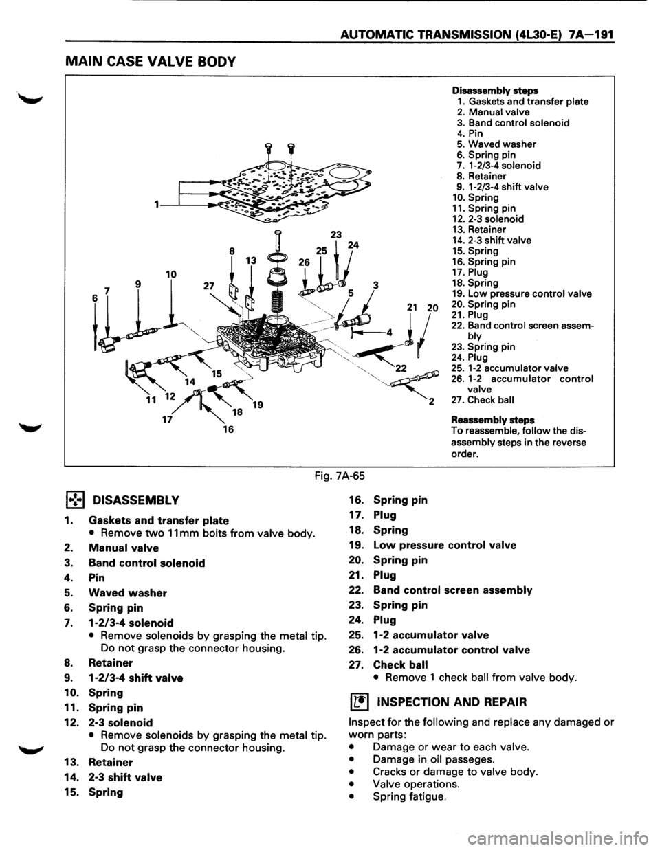
MAIN CASE VALVE BODY
1·:-1
1.
2.
3.
4.
5.
6.
7.
8.
9.
10.
11.
12.
13.
14.
15.
23
8 25 i 24
26
r t 1
~kY~ 3
"· u 21 20
/:: 14 4 11
~ 2
16
Fig. 7A-65
DISASSEMBLY 16. Spring pin
Gaskets
and transfer plate 17. Plug
Disassembly steps
1. Gaskets and transfer plate 2. Manual valve
3. Band control solenoid 4. Pin 5. Waved washer
6. Spring pin 7. 1-2/3-4 solenoid
8. Retainer 9. 1-2/3-4 shift valve 10. Spring
11. Spring pin 12. 2-3 solenoid
13. Retainer 14. 2-3 shift valve 15. Spring
16. Spring pin 17. Plug 18. Spring
19. Low pressure control valve
20. Spring pin 21. Plug
22. Band control screen assem-bly
23. Spring pin 24. Plug
25. 1-2 accumulator valve 26. 1-2 accumulator control valve
27. Check ball
Reassembly
steps
To reassemble,
follow the dis
assembly steps in the reverse
order.
• Remove two 11 mm bolts from valve body. 18. Spring
Manual valve 19. Low pressure control valve
Band control solenoid 20. Spring pin
Pin 21.
Plug
Waved washer 22.
Band control screen assembly
Spring pin 23. Spring pin
1-2/3-4 solenoid 24. Plug
•
Remove solenoids by grasping the metal tip. 25.
1-2 accumulator valve
Do not grasp the connector housing.
26. 1-2 accumulator control valve
Retainer 27. Check ball
1-2/3-4 shift valve • Remove 1 check ball from valve body.
Spring IL•I INSPECTION AND REPAIR Spring pin
2-3 solenoid Inspect for the following and replace any damaged or
• Remove solenoids by grasping the metal tip. worn parts:
Do
not grasp the connector housing. • Damage or wear to each valve.
Retainer • Damage in oil passages .
2-3
shift valve • Cracks or damage to valve body .
• Valve operations . Spring • Spring fatigue .
Page 1065 of 1928
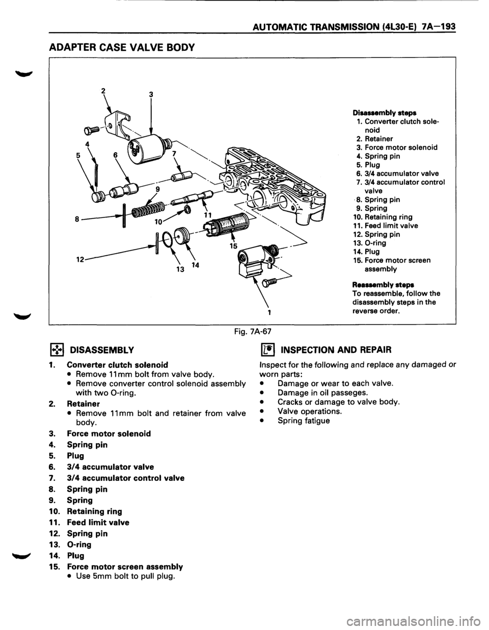
ADAPTER CASE VALVE BODY
AUTOMATIC TRANSMISSION (4L30-E) 7A-193
1
Disassembly steps
1. Converter clutch sole-
noid
2. Retainer
3. Force motor solenoid
4. Spring pin
5. Plug
6. 3/4 accumulator valve
7. 3/4 accumulator control
valve
·
8. Spring pin
9. Spring
10. Retaining ring
11. Feed limit valve
12. Spring pin
13. 0-ring
14. Plug
15. Force motor screen
assembly
Reassembly
steps
To
reassemble, follow the
disassembly steps in the
reverse order.
Fig. 7A-67
l.,!,.l DISASSEMBL V
1. Converter clutch solenoid
• Remove 11 mm bolt from valve body.
• Remove converter control solenoid assembly
with two 0-ring.
2. Retainer
• Remove 11 mm bolt and retainer from valve
body.
3. Force motor solenoid
4. Spring pin
5. Plug
6. 3/4 accumulator valve
7. 3/4 accumulator control valve
8. Spring pin
9.
Spring
10. Retaining ring
11. Feed
limit valve
12. Spring pin
13. 0-ring
14. Plug
15. Force motor screen assembly
• Use 5mm bolt to pull plug.
(L!] INSPECTION AND REPAIR
Inspect for the following and replace any damaged or
worn parts:
• Damage or wear to each valve.
•
Damage in oil passages.
• Cracks or damage to valve body.
• Valve operations.
• Spring fatigue
Page 1079 of 1928
AUTOMATIC TRANSMISSION (4L30-E) 7 A-207
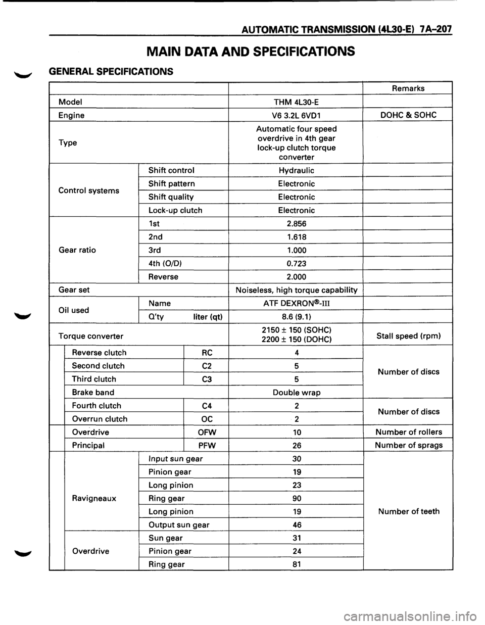
MAIN DATA AND SPECIFICATIONS
GENERAL SPECIFICATIONS
Remarks
Model THM 4L30-E
Engine
V6 3.2L 6VD1 DOHC&SOHC
Automatic four speed
Type overdrive
in 4th gear
lock-up clutch
torque
converter
Shift control Hydraulic
Shift pattern
Electronic Control systems Shift quality Electronic
Lock-up clutch Electronic
1st 2.856
2nd 1.618
Gear ratio
3rd
1.000
4th (0/0) 0.723
Reverse 2.000
Gear set
Noiseless, high torque capability
Name ATF
DEXRON®-m
Oil used O'ty liter (qt) 8.6 (9.1)
Torque
converter 2150 ± 150 (SOHC)
Stall speed (rpm) 2200 ± 150 (OOHC)
Reverse clutch RC 4
Second clutch
C2 5 Number of discs Third clutch C3 5
Brake band
Double
wrap
Fourth clutch C4 2 Number of discs
Overrun clutch oc 2
Overdrive
OFW 10 Number of rollers
Principal
PFW 26 Number of sprags
Input sun gear 30
Pinion gear 19
Long pinion 23
Ravigneaux Ring gear 90
Long pinion 19 Number of teeth
Output sun gear 46
Sun gear 31
Overdrive Pinion gear
24
Ring gear
81
Page 1083 of 1928
AUTOMATIC TRANSMISSION (4L30-E) 7 A-211
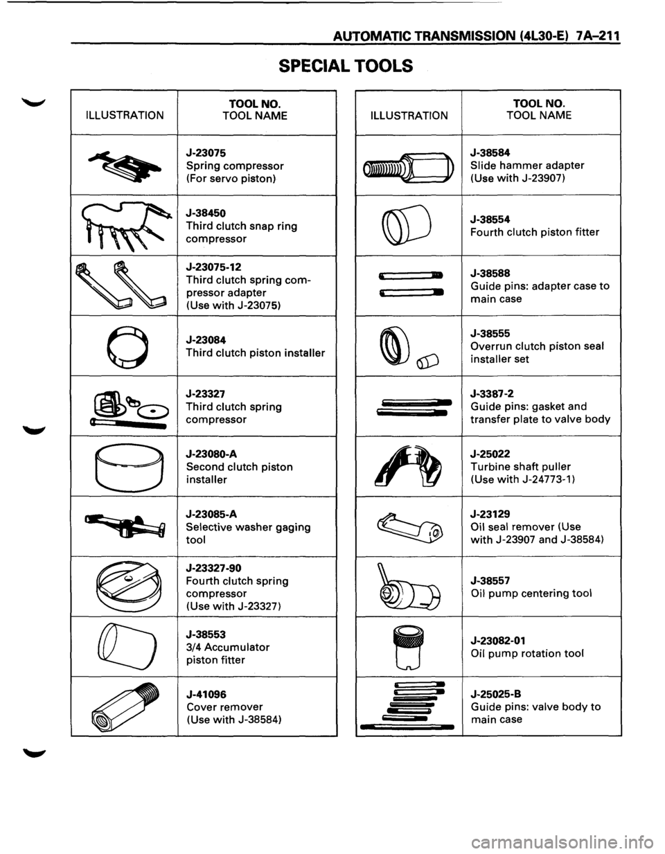
SPECIAL TOOLS
TOOL NO. TOOL
NO.
ILLUSTRATION
TOOL NAME ILLUSTRATION TOOL NAME
~
J-23075
Spring compressor
(For
servo piston) 011mwn ~
J-38584
Slide hammer adapter
(Use
with J-23907)
J-38450
Third clutch snap ring
,,"
compressor @]
J-38554
Fourth clutch piston
fitter
'~
J-23075-12
Third clutch spring com-
pressor adapter
(Use
with J-23075)
'
• J-38588
' •
Guide pins: adapter case to
main case
0
J-23084
Third clutch piston installer ~\1D
J-38555
Overrun
clutch piston seal
installer
set
~~~
J-23327
Third clutch spring
(t compressor
J-3387-2 Guide pins: gasket and
transfer plate to valve
body
8
J-23080-A
Second clutch piston
installer ~
J-25022
Turbine shaft puller
(Use with J-24773-1)
··~
J-23085-A
Selective washer gaging
tool ~
J-23129
Oil seal remover (Use
with J-23907 and J-38584)
®
J-23327-90
Fourth
clutch spring
compressor
(Use with J-23327) ~
J-38557
Oil pump centering tool
ra
J-38553
3/4
Accumulator
piston fitter ~
J-23082-01 Oil
pump rotation tool
~
J-41096 Cover remover
(Use
with J-38584)
~ J-25025-B
Guide pins: valve body to
main case
Page 1084 of 1928
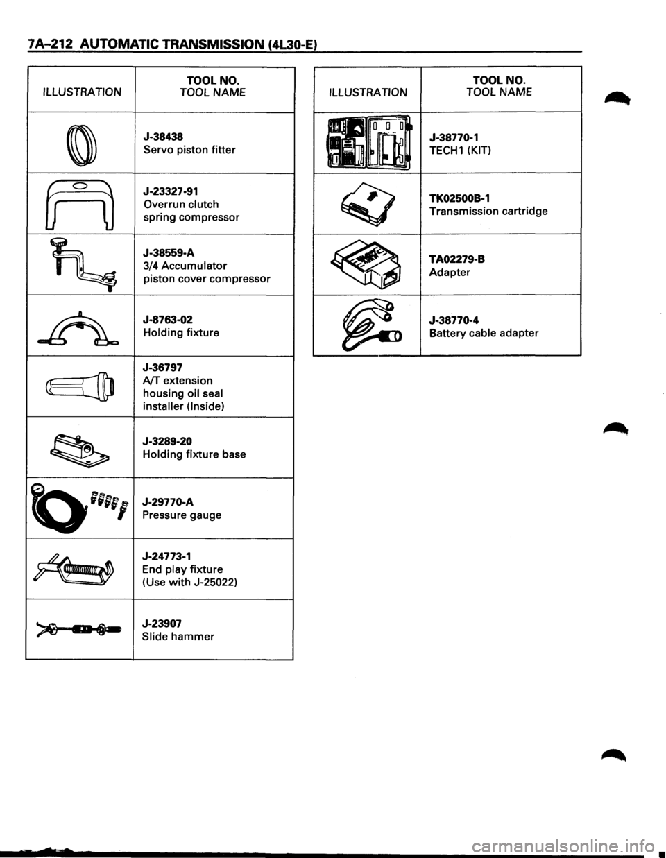
7A-212 AUTOMATIC TRANSMISSION (4L30-E)
TOOL NO.
ILLUSTRATION TOOL
NAME
0
J-38438
Servo piston
fitter
frO
J-23327-91
Overrun
clutch
spring compressor
~
J-38559-A
3/4
Accumulator
piston cover compressor
~
J-8763-02
Holding fixture
J-36797
@jtD A/T extension
housing
oil seal
installer (Inside)
~
J-3289-20
Holding fixture base
~''''I
J-29770-A
Pressure gauge
~
J-24773-1
End
play fixture
(Use
with J-25022)
~ 1:-i-J-23907
Slide hammer
ILLUSTRATION TOOL
NO.
TOOL NAME
J-38770-1
TECH1 (KIT)
TK02500B-1
Transmission cartridge
TA02279-B Adapter
J-38770-4 Battery
cable adapter
•
Page 1086 of 1928
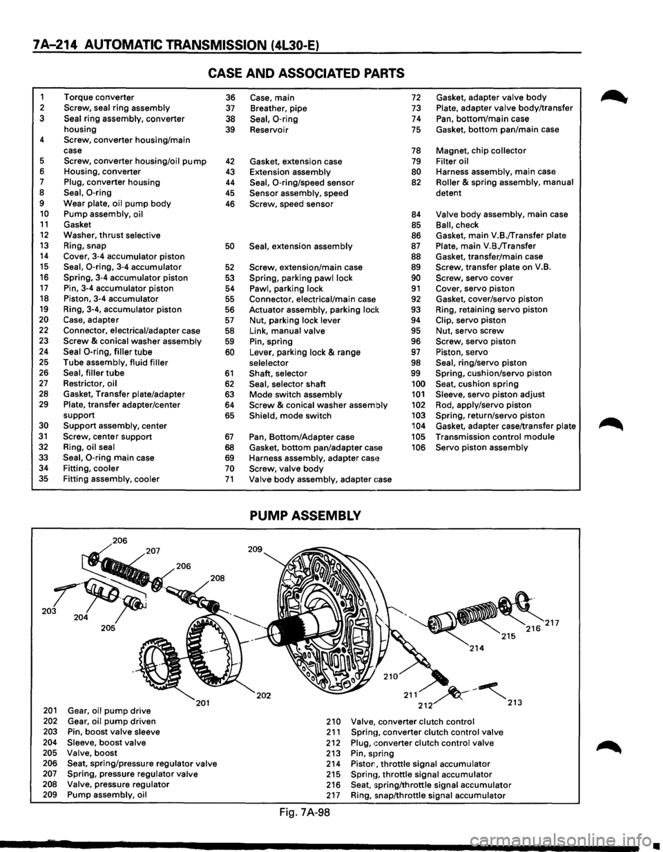
7A-214 AUTOMATIC TRANSMISSION (4L30-E)
CASE AND ASSOCIATED PARTS
1 Torque converter 2 Screw, seal ring assembly 3 Seal ring assembly, converter
housing
4 Screw, converter housing/main
case
5 Screw, converter housing/oil pump 6 Housing, converter 7 Plug, converter housing 8 Seal, 0-ring 9 Wear plate, oil pump body 10 Pump assembly, oil 11 Gasket 12 Washer, thrust selective 13 Ring, snap 14 Cover, 3-4 accumulator piston 15 Seal, 0-ring, 3-4 accumulator 16 Spring, 3-4 accumulator piston 17 Pin, 3-4 accumulator piston 18 Piston, 3-4 accumulator 19 Ring, 3-4, accumulator piston 20 Case, adapter 22 Connector, electrical/adapter case 23 Screw & conical washer assembly 24 Seal 0-ring, filler tube 25 Tube assembly, fluid filler 26 Seal, filler tube 27 Restrictor, oil 28 Gasket, Transfer plate/adapter 29 Plate, transfer adapter/center
support
30 Support assembly, center 31 Screw, center support 32 Ring, oil seal
33 Seal, 0-ring main case 34 Fitting, cooler 35 Fitting assembly, cooler
206
201 Gear, oil pump drive 202 Gear, oil pump driven 203 Pin, boost valve sleeve 204 Sleeve, boost valve 205 Valve, boost
201
206 Seat, spring/pressure regulator valve 207 Spring, pressure regulator valve 208 Valve, pressure regulator 209 Pump assembly, oil
36 37
38
39
42 43
44
45
46
50
52
53
54
55
56
57
58 59
60
61
62 63 64
65
67
68 69 70 71
Case, main 72 Gasket, adapter valve body
Breather, pipe 73 Plate, adapter valve body/transfer
Seal, 0-ring 74 Pan, bottom/main case
Reservoir
75 Gasket, bottom pan/main case
78 Magnet, chip collector
Gasket, extension case
79 Filter oil
Extension assembly
80 Harness assembly, main case
Seal, 0-ring/speed sensor 82 Roller & spring assembly, manual
Sensor assembly, speed detent Screw, speed
sensor 84 Valve body assembly, main case
85 Ball, check
86 Gasket, main V.B./Transfer plate
Seal, extension assembly 87 Plate, main V.B./Transfer
88 Gasket, transfer/main case
Screw, extension/main case 89 Screw, transfer plate on V.B.
Spring, parking pawl lock 90 Screw, servo cover
Pawl, parking lock 91 Cover, servo piston Connector, electrical/main case 92 Gasket, cover/servo piston
Actuator assembly, parking lock
93 Ring, retaining servo piston
Nut, parking lock lever 94 Clip, servo piston
Link, manual valve 95 Nut, servo screw
Pin, spring 96 Screw, servo piston
Lever, parking lock
& range 97 Piston, servo
selelector 98 Seal, ring/servo piston
Shaft, selector 99 Spring, cushion/servo piston
Seal, selector shaft 100 Seat, cushion spring
Mode switch assembly 101 Sleeve, servo piston adjust
Screw & conical washer assembly 102 Rod, apply/servo piston
Shield, mode switch 103 Spring, return/servo piston 104 Gasket, adapter case/transfer plate
Pan, Bottom/Adapter case 105 Transmission control module
Gasket,
bottom pan/adapter ca!~e 106 Servo piston assembly
Harness assembly, adapter
cas'~ Screw, valve body
Valve body assembly, adapter ~:ase
PUMP ASSEMBLY
202 211 ~-~ 212 . 213
210 Valve, converter clutch control 211 Sprinn, converter clutch control valve 212 Plug, converter clutch control valve 213 Pin, spring 214 Piston, throttle signal accumulator 215 Sprinn, throttle signal accumulator 216 Seat, 1;pring/throttle signal accumulator 217 Ring, snap/throttle signal accumulator
Fig. 7A-98
~
•
Page 1088 of 1928
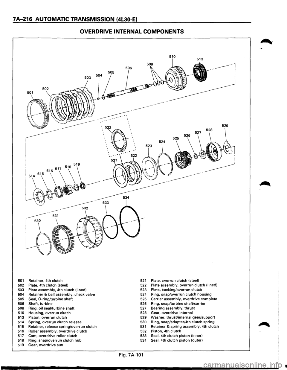
7A-216 AUTOMATIC TRANSMISSION (4L30-E}
OVERDRIVE INTERNAL COMPONENTS
501 Retainer, 4th clutch
502 Plate, 4th clutch (steel) 503
503 Plate assembly,
4th clutch (lined)
504 Retainer & ball assembly, check valve
505 Seal, 0-ring/turbine shaft 506 Shaft, turbine 508 Ring, oil seal/turbine shaft 510 Housing, overrun clutch 513 Piston, overrun clutch 514 Spring, overrun clutch release 515 Retainer, release spring/overrun clutch 516 Roller assembly, overdrive clutch 517 Cam, overdrive roller clutch 518 Ring, snap/overrun clutch hub 519 Gear, overdrive sun
\52\12 \, ' ' ' -' ' '
' ' ' ' ' J ------' -,_-
510
521 Plate, c•verrun clutch (steel) 522 Plate a~;sembly, overrun clutch (lined)
523 Plate, backing/overrun clutch 524 Ring, snap/overrun clutch housing
525 Carrier assembly, overdrive complete 526 Ring, snap/turbine shaft/carrier
527 Bearin~1 assembly, thrust 528 Gear, overdrive internal 529 Washer, thrust/internal gear/support 530 Ring, snap/adapter/4th clutch spring 531 Retainer & spring assembly, 4th clutch 532 Piston, 4th clutch 533 Seal, 4th clutch piston (inner)
534 Seal, 4th clutch piston (outer)
Fig. 7A-101
529
•
Page 1093 of 1928
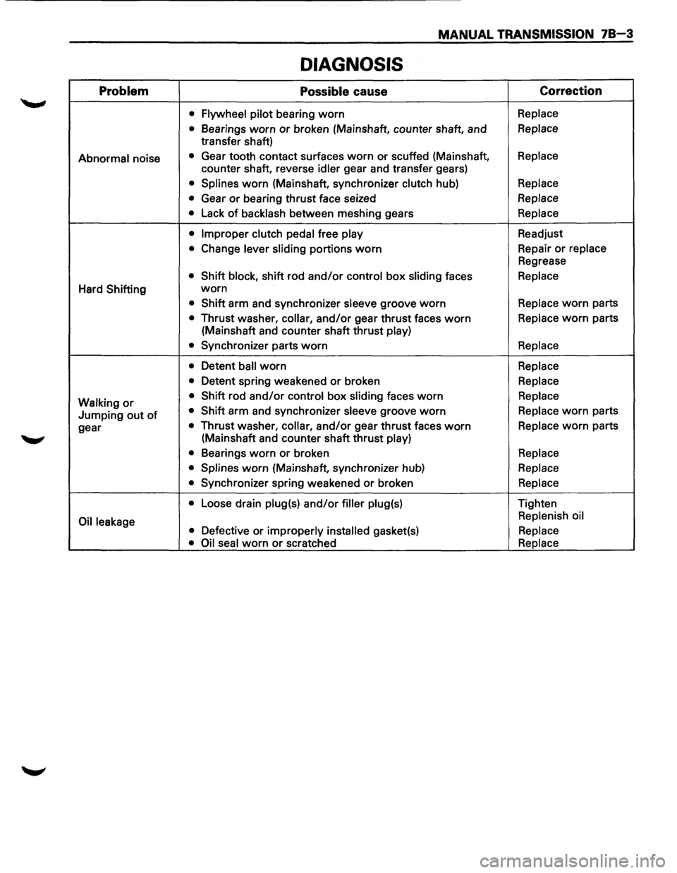
MANUAL TRANSMISSION 78-3
DIAGNOSIS
Problem Possible cause Correction
•
Flywheel pilot bearing worn Replace
•
Bearings worn or broken (Mainshaft, counter shaft, and Replace
transfer shaft)
Abnormal noise • Gear tooth contact surfaces worn or scuffed (Mainshaft, Replace
counter shaft, reverse idler gear and transfer gears)
• Splines worn (Mainshaft, synchronizer clutch hub) Replace
•
Gear or bearing thrust face seized Replace
•
Lack of backlash between meshing gears Replace
• Improper clutch pedal
free play Readjust
• Change lever sliding portions worn Repair or replace
Regrease
• Shift block, shift rod and/or control box sliding faces Replace
Hard Shifting worn
• Shift arm and synchronizer sleeve groove worn Replace worn parts
• Thrust washer, collar, and/or gear thrust faces worn Replace worn parts
(Mainshaft and counter shaft thrust
play)
•
Synchronizer parts worn Replace
•
Detent ball worn Replace
•
Detent spring weakened or broken Replace
Walking
or • Shift rod and/or control box sliding faces worn Replace
Jumping out of • Shift arm and synchronizer sleeve groove worn Replace worn parts
gear
• Thrust washer, collar, and/or gear thrust faces worn Replace worn parts
(Mainshaft and counter shaft thrust
play)
•
Bearings worn or broken Replace
• Splines
worn (Mainshaft, synchronizer hub) Replace
•
Synchronizer spring weakened or broken Replace
•
Loose drain plug(s) and/or filler plug(s) Tighten
Oil leakage Replenish
oil
• Defective or improperly installed gasket(s) Replace
• Oil seal
worn or scratched Replace
Page 1102 of 1928
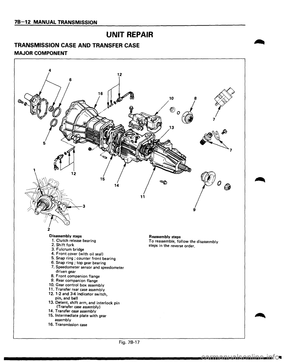
78-12 MANUAL TRANSMISSION
UNIT REPAIR
TRANSMISSION CASE AND TRANSFER CASE
MAJOR COMPONENT
4
11
2
Disassembly steps Reassembly steps 7
~
9
1. Clutch release
bearing 2. Shift fork
3. Fulcrum bridge To reassemble, follow the disassembly
steps in the reverse order.
4.
Front cover (with oil seal)
5. Snap ring ; counter front bearing
6. Snap ring ; top gear bearing
7. Speedometer sensor and speedometer
driven gear
8. Front companion flange
9. Rear companion flange
10. Gear control box assembly
11. Transfer rear case assembly
12.
1·2 and 3-4 indicator switch,
pin, and ball 13. Detent, shift arm, and interlock pin
(Transfer case assembly) 14. Transfer case assembly
15. Intermediate plate with gear
assembly
16. Transmission case
Fig. 78-17
7
Ill
Page 1103 of 1928
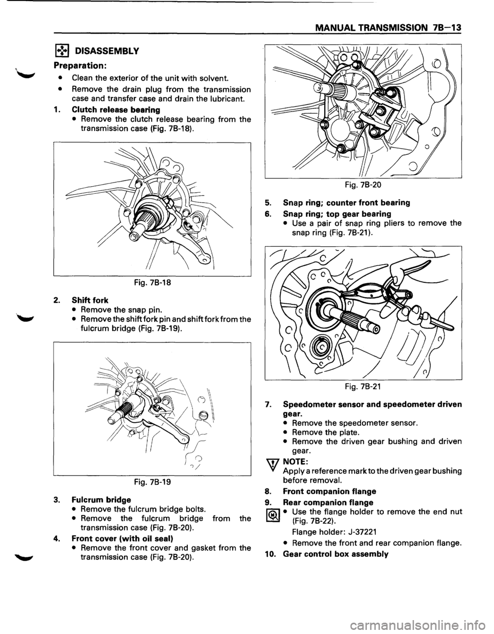
1•!,.1 DISASSEMBLY
Preparation:
• Clean the exterior of the unit with solvent.
•
Remove the drain plug from the transmission
case and transfer case and drain the
lubricant.
1. Clutch release bearing
• Remove the clutch release bearing from the
transmission case (Fig.
78-18).
Fig. 78-18
2. Shift fork
• Remove the snap pin.
''-" • Remove the shift fork pin and shift fork from the
fulcrum bridge (Fig. 78-19).
Fig. 78-19
3. Fulcrum bridge
• Remove the fulcrum bridge bolts.
•
Remove the fulcrum bridge from the
transmission case (Fig.
78-20).
4. Front cover (with oil seal)
• Remove the front cover and gasket from the
transmission case (Fig.
78-20).
MANUAL TRANSMISSION 78-13
Fig. 78-20
5. Snap ring; counter front bearing
6. Snap ring; top gear bearing
• Use a pair of snap ring pliers to remove the
snap ring (Fig.
78-21 ).
Fig. 78-21
1. Speedometer sensor and speedometer driven
gear.
• Remove the speedometer sensor.
• Remove the plate.
•
Remove the driven gear bushing and driven
gear.
'\fl NOTE:
VI Apply a reference mark to the driven gear bushing
before
removal.
8. Front companion flange
9. Rear companion flange
l'ia\1 • Use the flange holder to remove the end nut
~ (Fig. 78-22).
Flange holder: J-37221
• Remove the front and rear companion flange.
10. Gear control box assembly