oil ISUZU TROOPER 1995 Workshop Manual
[x] Cancel search | Manufacturer: ISUZU, Model Year: 1995, Model line: TROOPER, Model: ISUZU TROOPER 1995Pages: 1928
Page 1033 of 1928
1••1 REMOVAL
Preparation:
• Remove engine hood.
• Disconnect negative (-) battery cable.
1. Skid plate
2. Exhaust and transfer protectors
3. Rear propeller shaft
4. Front propeller shaft
5. Exhaust pipe
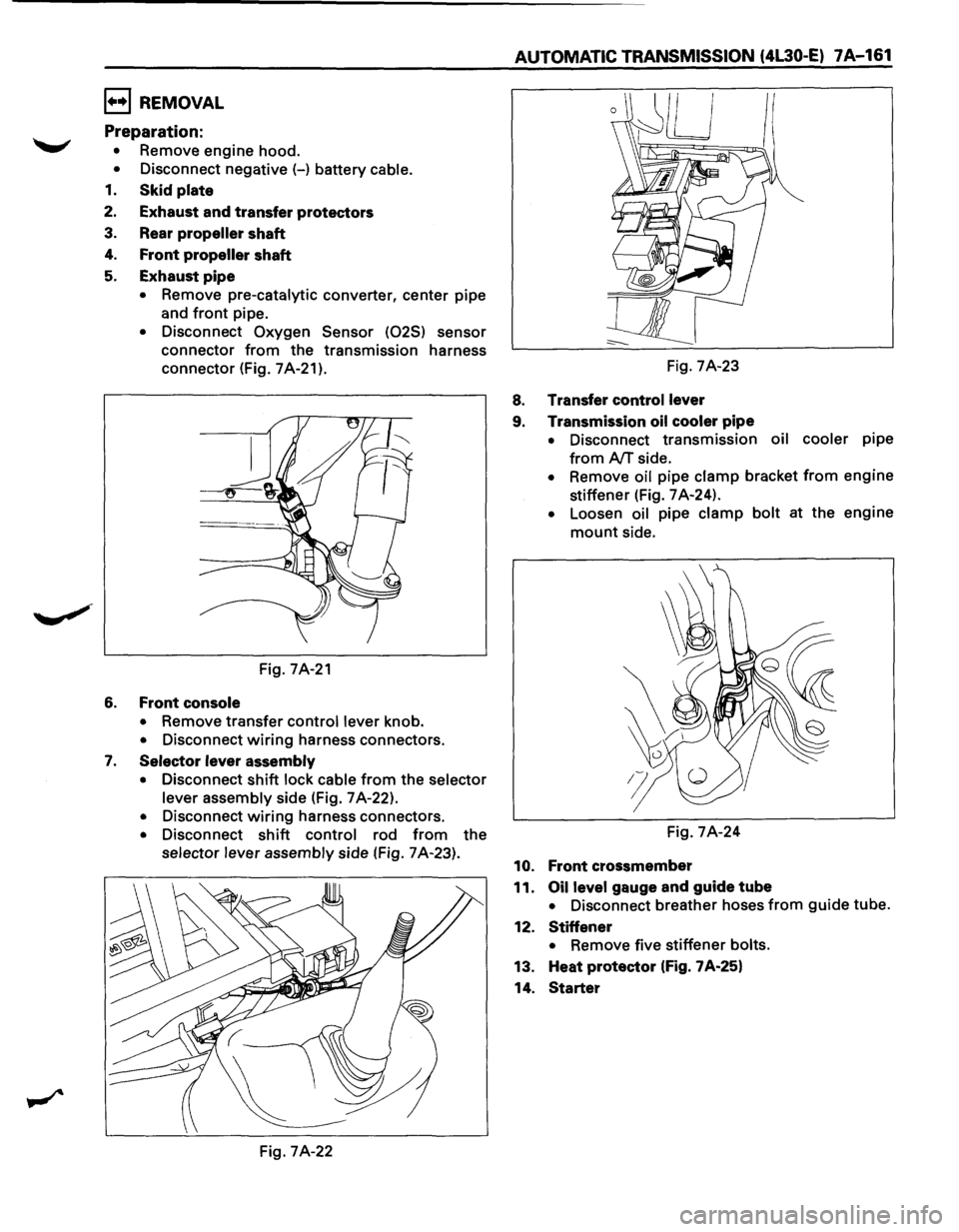
• Remove pre-catalytic converter, center pipe
and
front pipe.
• Disconnect Oxygen Sensor (025) sensor
connector
from the transmission harness
connector (Fig.
7A-21).
Fig. 7A-21
6. Front console
• Remove transfer control lever knob.
• Disconnect wiring harness connectors.
7. Selector lever assembly
• Disconnect shift lock cable from the selector
lever assembly
side (Fig. 7 A-22).
• Disconnect wiring harness connectors.
• Disconnect shift control rod from the
selector lever assembly side (Fig. 7 A-23).
Fig. 7A-22
AUTOMATIC TRANSMISSION (4L30·E) 7A-161
Fig. 7A-23
8. Transfer control lever
9. Transmission oil cooler
pipe
• Disconnect transmission oil cooler pipe
from AfT side.
• Remove oil pipe clamp bracket from engine
stiffener (Fig.
7 A-24).
• Loosen oil pipe clamp bolt at the engine
mount side.
Fig.
7A-24
10. Front crossmember
11.
Oil level gauge and guide tube
• Disconnect breather hoses from guide tube.
12.
Stiffener
• Remove five stiffener bolts.
13. Heat protector (Fig. 7A-25}
14.
Starter
Page 1036 of 1928
7A-164 AUTOMATIC TRANSMISSION (4L30-E)
20. Third crossmember
~~~ Torque N·m(lb.ft) 50 (37)
19. Rear mount nut
~~~ Torque N·mOb·ft) 41 (30)
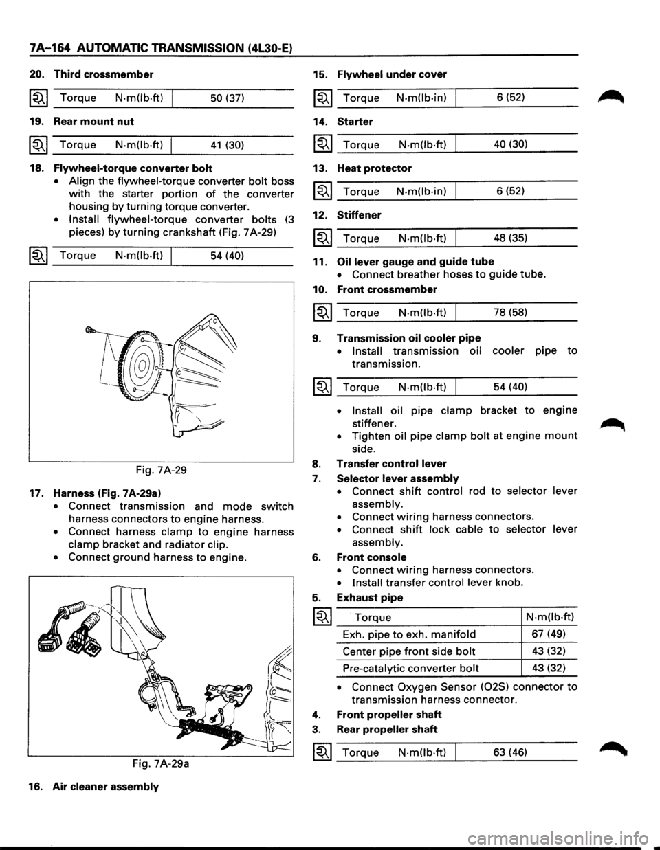
18. Flywheel-torque converter bolt
• Align
the flywheel-torque converter bolt boss
with the starter portion of the converter
housing
by turning torque converter.
• Install flywheel-torque converter bolts (3
pieces) by turning crankshaft (Fig. 7 A-29)
~~~ Torque N·mOb·ft) 54 (40)
Fig. 7A-29
17. Harness (fig. 7A-29a)
• Connect transmission and mode switch
harness connectors to engine harness.
• Connect harness clamp to engine harness
clamp bracket and radiator clip.
•
Connect ground harness to engine.
Fig. 7A-29a
16. Air
cleaner assembly
15. Flywheel under cover
~~~ TorqUte N·mOb·in)
14. Starter
~~~ Torqu,e N·m(lb·ft)
13. Heat protector
~~~ Torqu'e N·m(lb·in)
12. Stiffener
N·m(lb·ft)
11. Oil lever gauge and guide tube 6
(52)
40 (30)
6 (52)
48 (35)
• Connect breather hoses to guide tube.
10. Front crossmember
~~~ Torque N·m(lb·ft) I 78 (58)
9. Transmission oil cooler pipe
• Install transmission oil cooler pipe to
transmission.
~~~ Torqwe N·m(lb·ft) I 54 (40)
•
lnsta1ll oil pipe clamp bracket to engine
stiffener. .~
• Tighten oil pipe clamp bolt at engine mount
side.
8. Transfer control lever
7. Selector lever assembly
•
Connect shift control rod to selector lever
assembly.
•
Connect wiring harness connectors.
• Connect shift lock cable to selector lever
assembly.
6. Front cc>nsole
• Connect wiring harness connectors.
• Install transfer control lever knob.
5. Exhaust pipe
I~I ___ T_o_r_q~_ue __________________ 4-N_·_m_(l_b_·ft __ )
Exh. pipe
to exh. manifold 67 (49)
Center pipe
front side bolt 43 (32)
Pre-catalytic converter bolt 43 (32)
• Connect Oxygen Sensor (025) connector to
transmission harness connector.
4. Front propeller shaft
3. Rear propeller shaft
~~~ Torqwe N·mOb·ft) 63 (46)
Page 1037 of 1928
2. Exhaust and transfer protectors
~~~ Torque N-m(lb.ft) 37 (27)
1. Skid plate
• Connect negative (-) battery cable.
• Install
engine hood.
• Adjust shift lock cable.
Refer to "Selector lever" in this section.
SOLENOID VALVE
(MAIN CASE VALVE BODY)
l••l REMOVAL
Preparation:
• Disconnect negative {-) battery cable.
•
Remove exhaust protector and exhaust pipe.
1. Main case oil pan
• Remove sixteen 10 mm screws, main case
oil pan, magnet, and gasket.
• Drain fluid.
Refer to "CHANGING TRANSMISSION
FLUID".
2. Oil filter
• Remove three 13 mm screws, oil filter.
3. Wiring harness
• Disconnect wiring harness from band control
solenoid,
shift solenoids and main case 4 pin
connector.
Pull only on connectors, not on
wiring harness.
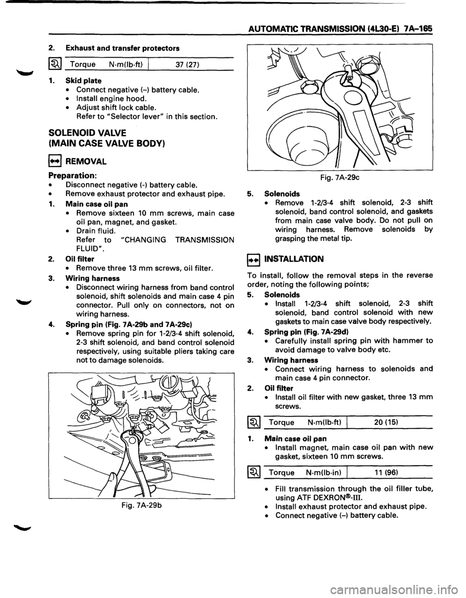
4. Spring pin (Fig. 7 A-29b and 7 A-29c)
• Remove spring pin for 1-2/3-4 shift solenoid,
2-3 shift solenoid, and band control solenoid
respectively,
using suitable pliers taking care
not to damage solenoids.
Fig. 7A-29b
AUTOMATIC TRANSMISSION (4L30 .. E) 7A-165
Fig. 7A-29c
5. Solenoids
• Remove 1-2/3-4 shift solenoid, 2-3 shift
solenoid, band control solenoid, and gaskets
from main case valve body. Do not pull on
wiring harness. Remove
· solenoids by
grasping the
metal tip.
I••! INSTALLATION
To install, follow the removal steps in the reverse
order,
noting the following points;
5. Solenoids
• Install 1-2/3-4 shift solenoid, 2-3 shift
solenoid, band control solenoid with new
gaskets to main case valve body respectively.
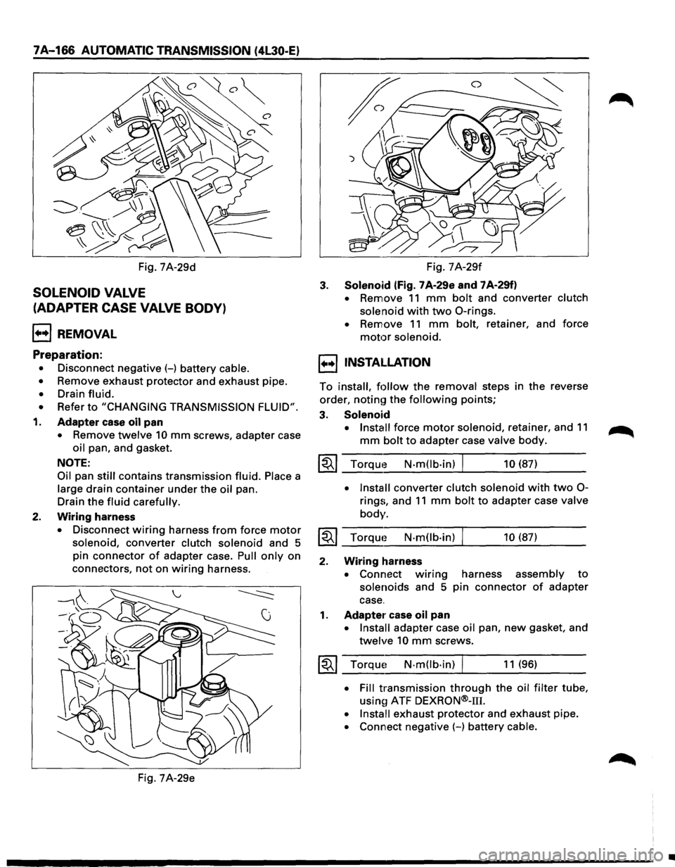
4. Spring pin (Fig. 7 A·29d)
• Carefully install spring pin with hammer to
avoid damage to valve body etc.
3. Wiring harness
• Connect wiring harness to solenoids and
main case 4 pin connector.
2. Oil filter
• Install oil filter with new gasket, three 13 mm
screws.
~~~ Torque N·m(lb.ft) 20 (15)
1. Main case oil pan
•
Install magnet, main case oil pan with new
gasket, sixteen 10 mm screws.
1~1 Torque N·m(lb·in) J 11 (96)
• Fill transmission through the oil filler tube,
using ATF DEXRQN®-m.
• Install exhaust protector and exhaust pipe.
• Connect negative (-) battery cable.
Page 1038 of 1928
7A-166 AUTOMATIC TRANSMISSION (4l30-E)
Fig. 7A-29d
SOLENOID VALVE
(ADAPTER CASE VALVE BODY)
l++l REMOVAL
Preparation:
• Disconnect negative(-) battery cable.
• Remove exhaust protector and exhaust pipe.
• Drain fluid.
• Refer to "CHANGING TRANSMISSION FLUID".
1. Adapter case oil pan
• Remove twelve 10 mm screws, adapter case
oil pan, and gasket.
NOTE:
Oil pan still contains transmission fluid. Place a
large
drain container under the oil pan.
Drain
the fluid carefully.
2. Wiring harness
• Disconnect wiring harness from force motor
solenoid, converter clutch solenoid and 5
pin
connector of adapter case. Pull only on
connectors,
not on wiring harness.
Fig. 7A-29e Fig.
7A-29f
3. Solenoid (fig. 7 A-29e and 7 A-29f)
• Remove 11 mm bolt and converter clutch
solenoid
with two 0-rings.
• Remove 11 mm bolt, retainer, and force
motor solenoid.
1••1 INSTALLATION
To install, follow the removal steps in the reverse
order,
noting the following points;
3. Solenoid
• Install force motor solenoid, retainer, and 11
mm bolt to adapter case valve body.
~~~ Torque N-m(lb-in) I 10 (87)
• Install converter clutch solenoid with two 0-
rings, and 11 mm bolt to adapter case valve
body.
~~~ Torque N-mOb·in) 10 (87)
2. Wiring harness
• Connect w1nng harness assembly to
solenoids and 5 pin connector of adapter
case.
1. Adapter case oil pan
• Install adapter case oil pan, new gasket, and
twelve 10 mm screws.
~~~ Torque~ N·mOb·in) I 11 (96)
• Fill transmission through the oil filter tube,
usin~1 ATF DEXRON®-111.
• Install exhaust protector and exhaust pipe.
• Connect negative (-) battery cable.
•
Page 1039 of 1928
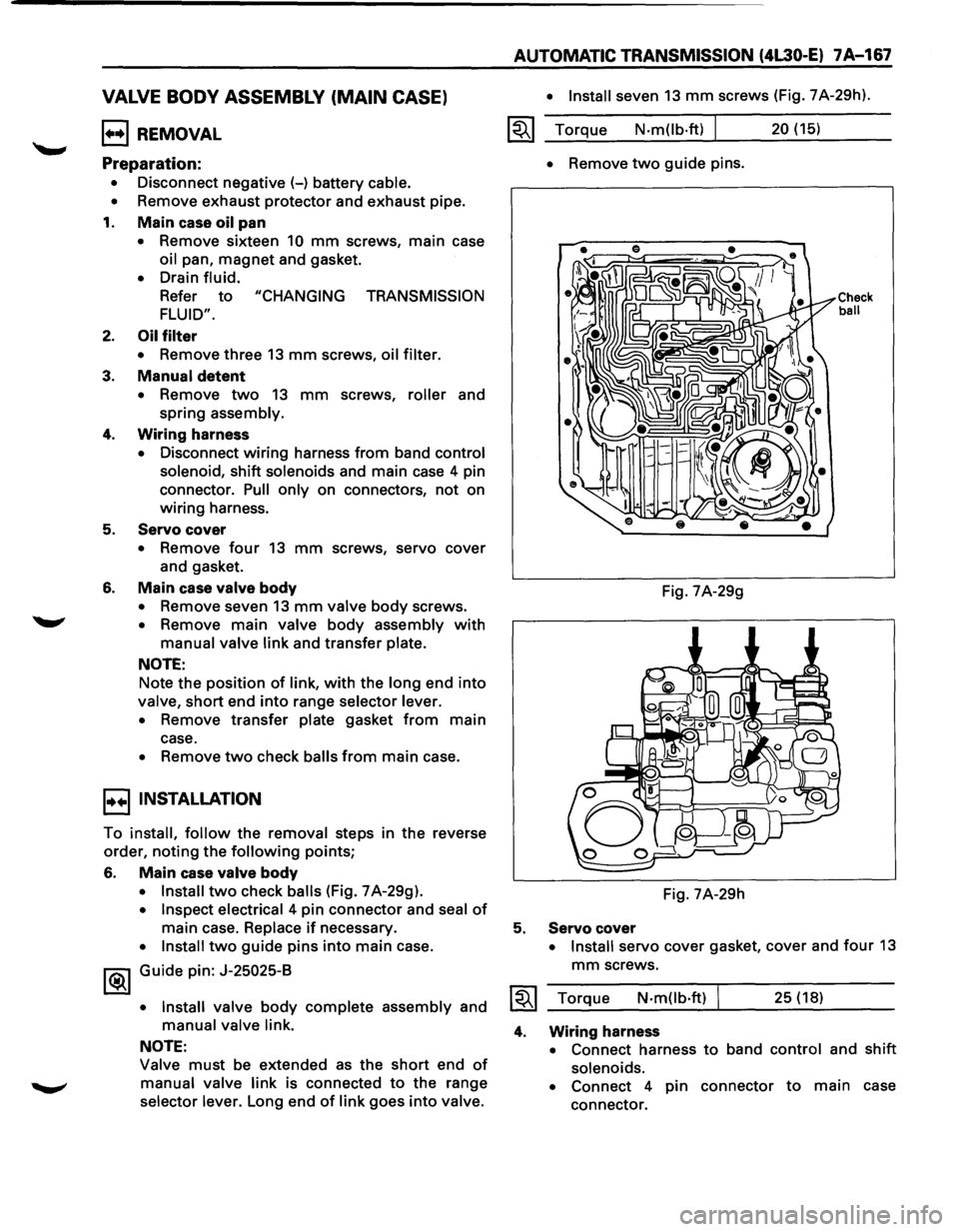
VALVE BODY ASSEMBLY (MAIN CASE)
1••1 REMOVAL
Preparation:
• Disconnect negative (-) battery cable.
• Remove exhaust protector and exhaust pipe.
1. Main case oil pan
• Remove sixteen 10 mm screws, main case
oil pan,
magnet and gasket.
• Drain fluid.
Refer
to "CHANGING TRANSMISSION
FLUID".
2. Oil filter
•
Remove three 13 mm screws, oil filter.
3. Manual detent
• Remove two 13 mm screws, roller and
spring assembly.
4. Wiring harness
• Disconnect wiring harness from band control
solenoid, shift solenoids and main
case 4 pin
connector.
Pull only on connectors, not on
wiring harness.
5.
Servo cover
• Remove four 13 mm screws, servo cover
and gasket.
6. Main case valve body
• Remove seven 13 mm valve body screws.
• Remove main valve body assembly with
manual valve link and transfer plate.
NOTE:
Note the position of link, with the long end into
valve, short end into range selector lever.
• Remove transfer plate gasket from main
case.
• Remove two check balls from main case.
I••IINSTALLATION
To install, follow the removal steps in the reverse
order,
noting the following points;
6. Main
case valve body
• Install two check balls (Fig. 7 A-29g).
• Inspect electrical 4 pin connector and seal of
main case. Replace if necessary.
• Install two guide pins into main case.
1®.1 Guide pin: J-25025-B
• Install
valve body complete assembly and
manual valve link.
NOTE:
Valve must be extended as the short end of
manual valve link is connected to the range
selector lever. Long end
of link goes into valve.
AUTOMATIC TRANSMISSION (4L30-E) 7A-167
• Install seven 13 mm screws (Fig. 7A-29h).
~~~ Torque N·m(lb·ft) I 20 (15)
5.
4.
• Remove two guide pins.
Fig. 7A-29g
Fig. 7A-29h
Servo cover
Check ball
• Install servo cover gasket, cover and four 13
mm screws.
Torque
N·mOb·ft) I 25 (18)
Wiring harness
• Connect harness to band control and shift
solenoids.
• Connect 4 pin connector to main case
connector.
Page 1040 of 1928
7A-168 AUTOMATIC TRANSMISSION (4L30-E)
3. Manual detent
• Install roller and spring assembly.
• Install
two 13 mm screws.
~~~ Torque N·m(lb.ft) I 20 (15)
2. Oil filter
• Install oil filter and three 13 mm screws.
~~~ Torque N-m(lb.ft) I 20 (15)
1. Main case oil pan
• Install oil pan gasket, magnet, oil pan and
sixteen
10 mm screws.
~~~ Torque N·m(lb-in) I 11 (96)
• Fill transmission through the oil filler tube,
using ATF
DEXRON®-111.
• Install exhaust pipe and exhaust protector.
• Connect negative (-) battery cable.
VALVE BODY ASSEMBLY (ADAPTER CASE)
1++1 REMOVAL
Preparation:
• Disconnect negative (-) battery cable.
•
Remove exhaust protector and exhaust pipe.
• Drain fluid.
•
Refer to "CHANGING TRANSMISSION FLUID".
1. Adapter case oil pan
• Remove twelve 10 mm screws, adapter case
oil pan and gasket.
NOTE:
Oil pan still contains transmission fluid. Place a
large drain container under the oil pan.
Drain the
fluid carefully.
2. Wiring harness
• Disc;:mnect wiring harness from force motor
solenoid, converter clutch solenoid and 5
pin
connector of adapter case. Pull only on
connectors,
not on wiring harness.
• Remove wiring harness.
3. Adapter case valve body
• Seve~n 13 mm screws, adapter case valve
body assembly, transfer plate and two
gaskets.
1++1 INSTALLATION
To install, follow the removal steps in the reverse
order,
notin~r the following points;
3. Adapter case valve body
• Inspect electrical 5 pin connector and seal of
adapter case. Replace if necessary.
• Install wiring harness assembly in bottom
of adapter case.
• Install gasket, transfer plate and gasket.
• Install adapter case valve body complete
and seven 13 mm screws.
~~~ Torque1 N·mOb·ft) 20 (15)
2. Wiring harness
• Connect harness assembly to converter
clutch solenoid and force motor.
1. Adapter case oil pan
• Instal!! oil pan gasket, oil pan and twelve 10
mm screws.
~~~ Torque N-m(lb-in) I 11 (96)
• Fill transmission through the oil filter tube,
using1 ATF DEXRON®-m.
• Install exhaust pipe and exhaust protector. ~
• Connect negative (-) battery cable.
•
Page 1042 of 1928
7 A-170 AUTOMATIC TRANSMISSION (4L30-E)
TRANSMISSION OIL TEMPERATURE
SENSOR (ADAPTER CASE)
1•+1 REMOVAL
Preparation:
• Disconnect negative (-) battery cable.
•
Remove exhaust protector and exhaust pipe.
• Drain fluid.
•
Refer to "CHANGING TRANSMISSION FLUID".
1. Adapter case oil pan
• Remove twelve 10 mm screws, adapter case
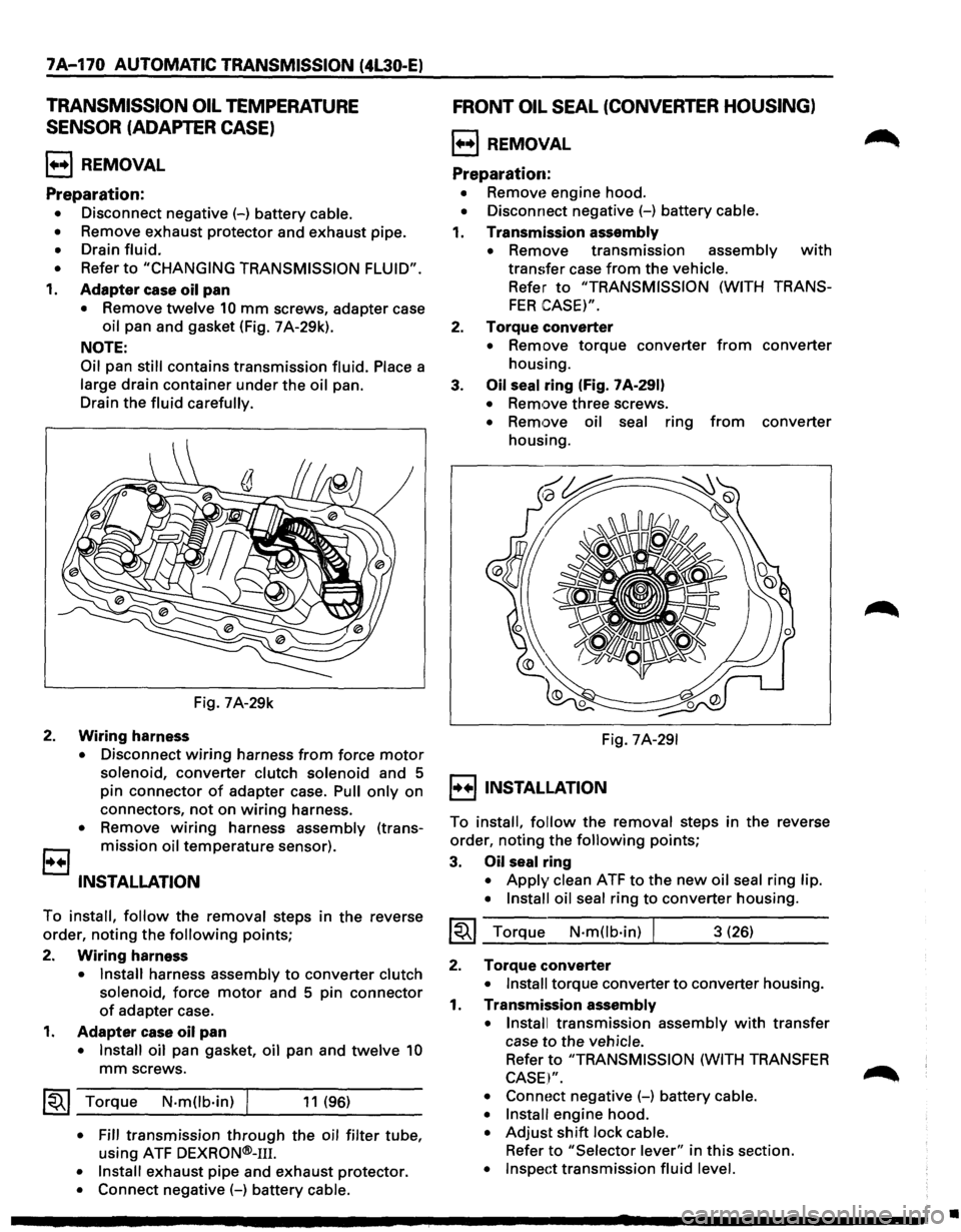
oil pan and gasket (Fig. 7 A-29k).
NOTE:
Oil
pan still contains transmission fluid. Place a
large drain container under the oil pan.
Drain the
fluid carefully.
Fig. 7A-29k
2. Wiring harness
• Disconnect wiring harness from force motor
solenoid, converter clutch solenoid and 5
pin connector
of adapter case. Pull only on
connectors,
not on wiring harness.
• Remove wiring harness assembly (trans
B mission oil temperature sensor).
INSTALLATION
To install, follow the removal steps in the reverse
order, noting the
following points;
2.
Wiring harness
• Install harness assembly to converter clutch
solenoid,
force motor and 5 pin connector
of adapter case.
1. Adapter case oil pan
• Install oil pan gasket, oil pan and twelve 10
mm screws.
~~~ Torque N·mOb·in) I 11 (96)
• Fill transmission through the oil filter tube,
using ATF
DEXRON®-111.
• Install exhaust pipe and exhaust protector.
• Connect negative (-) battery cable.
FRONT OIL SEAL (CONVERTER HOUSING)
l++l REMOVAL
Preparation:
• Removt~ engine hood.
• Disconnect negative (-) battery cable.
1. Transmission assembly
•
Remove transmission assembly with
transfer case from the vehicle.
Refer to "TRANSMISSION (WITH TRANS
FER CASE)".
2. Torque converter
• Remove torque converter from converter
housing.
3.
Oil seal ring (Fig. 7 A-291)
• Remove three screws.
• Remove oil seal ring from converter
housing.
Fig.
7A-291
I++IINSTALLATION
To install, follow the removal steps in the reverse
order, noting the
following points;
3. Oil seal ring
• Apply clean ATF to the new oil seal ring lip.
• Install oil seal
ring to converter housing.
~~~ Torque N·mOb·in) I 3 (26)
2. Torque converter
• Install torque converter to converter housing.
1. Transmission assembly
• Install
transmission assembly with transfer
case
to the vehicle.
Refer to "TRANSMISSION (WITH TRANSFER
CASE I".
• Connoct negative (-) battery cable.
• Install
engine hood.
• Adjust shift lock cable.
Refer to "Selector lever" in this section.
• Inspect transmission fluid level.
•
Page 1043 of 1928
REAR OIL SEAL (EXTENSION HOUSING)
l••l REMOVAL
Preparation:
• Disconnect negative (-) battery cable.
1. Transfer case assembly
• Remove transfer case assembly from the
vehicle.
Refer to "SECTION 70 TRANSFER CASE
(AfT')".
2. Rear oil seal
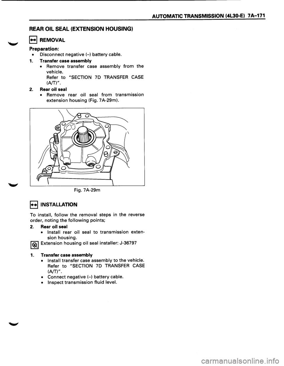
• Remove rear oil seal from transmission
extension housing (Fig. 7A-29m).
Fig. 7A-29m
I••IINSTALLATION
To install, follow the removal steps in the reverse
order,
noting the following points;
2. Rear oil seal
• Install rear oil seal to transmission exten
sion housing.
1®..1 Extension housing oil seal installer: J-36797
1. Transfer case assembly
• Install transfer case assembly to the vehicle.
Refer to "SECTION 70 TRANSFER CASE
(AfT')".
• Connect negative (-) battery cable.
• Inspect
transmission fluid level.
AUTOMATIC TRANSMISSION (4L30·E) 7A-171
Page 1045 of 1928
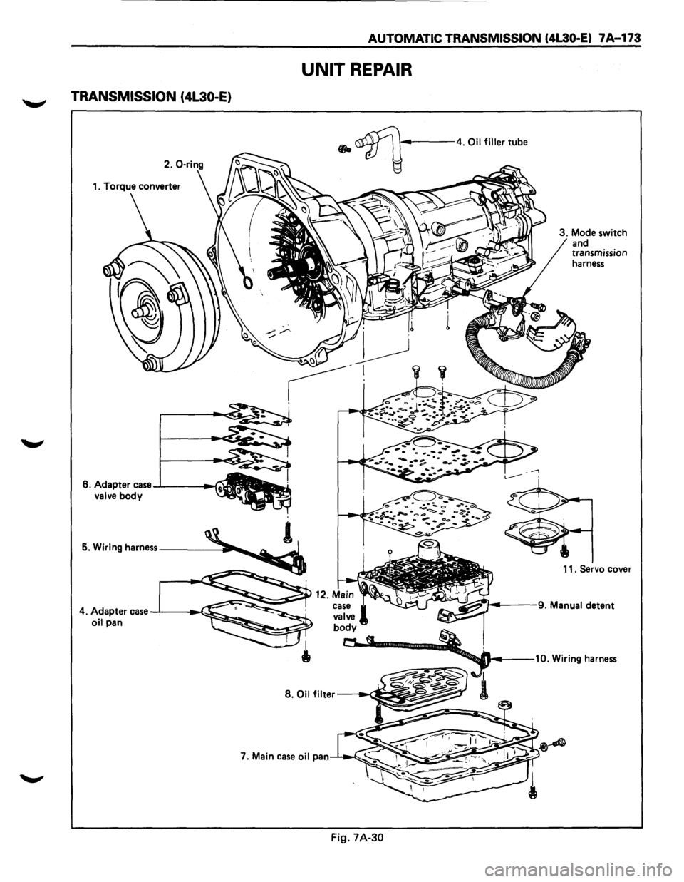
TRANSMISSION (4L30-E)
6. Adapter case -l------f valve body
AUTOMATIC TRANSMISSION (4L30-E) 7 A-173
UNIT REPAIR
• ~-----4. Oil filler tube
3. Mode switch
and
transmission
harness
11. Servo cover
case
valve body
~ §,.::•·• ~~--... ---10. Wiring harness
---1 ..... ~ 1 S.Oilfilter -~
I
Fig. 7A-30
Page 1046 of 1928
7A-174 AUTOMATIC TRANSMISSION (4L30·E)
1•!•1 biSASSEMBLV
During the disassembly and reassembly of the
following components, perform the following:
• Wash each part thoroughly and blow air
through each oil passage and groove to
eliminate blockage.
• Seal rings, roll pins and gaskets should be
replaced
with new parts.
• When assembling the components, apply
DEXRON®-m Automatic Transmission Fluid
(ATF)
to each seal, rotating part and sliding
part.
• Do not dip those parts having a facing, such as
drive plate for clutch or brake, in the cleaner
when washing it with solvent.
Also, always wash
it with new ATF two or
three times after cleaning with solvent.
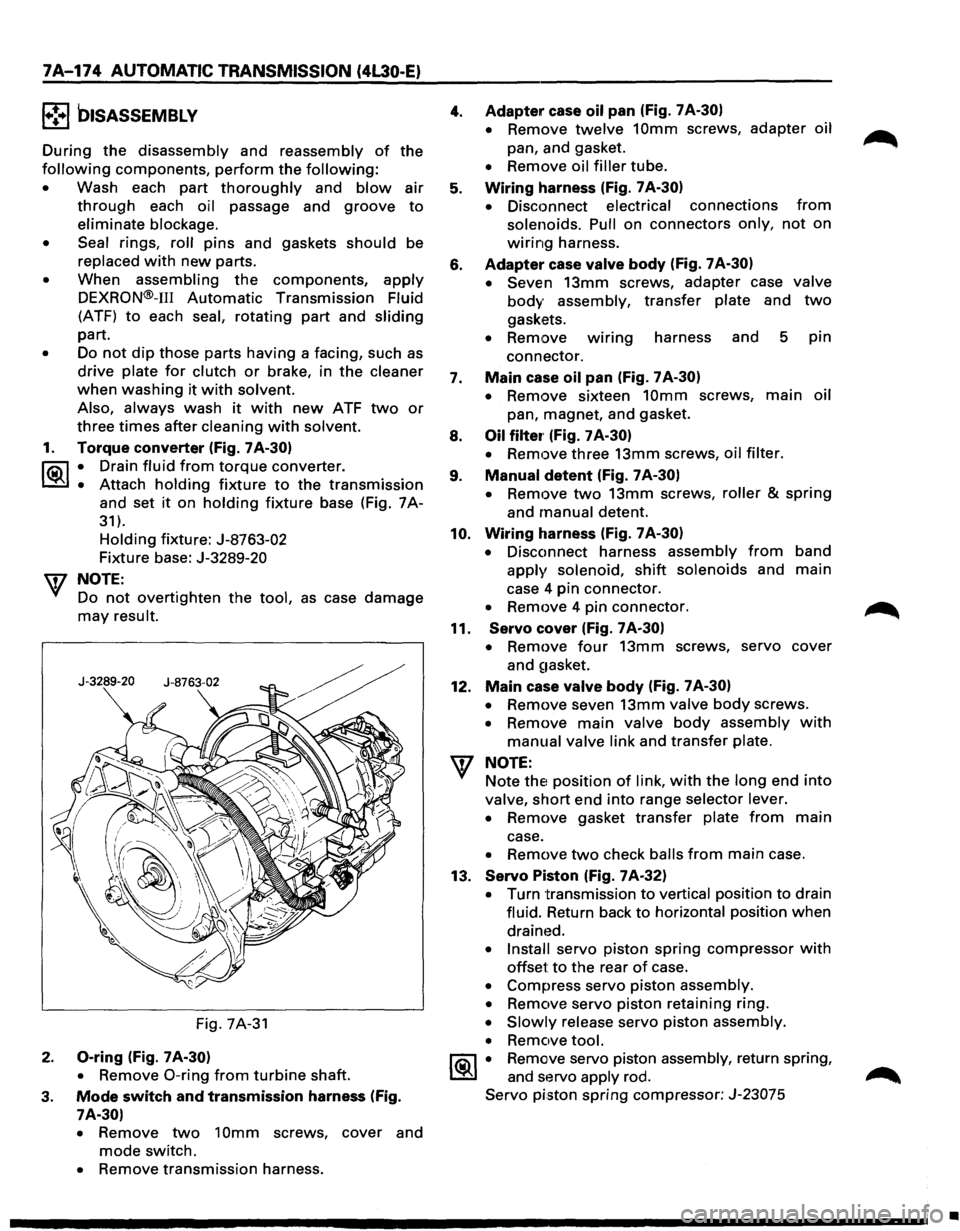
1. Torque converter (Fig. 7A-30)
l"i:\1 • Drain fluid from torque converter.
~ • Attach holding fixture to the transmission
and set it on holding fixture base (Fig. 7A-
31).
Holding fixture: J-8763-02
Fixture base: J-3289-20
w NOTE:
Do
not overtighten the tool, as case damage
may result.
Fig. 7A-31
2. 0-ring (Fig. 7 A-30)
•
Remove 0-ring from turbine shaft.
3. Mode switch and transmission harness (Fig.
7A-30)
•
Remove two 10mm screws, cover and
mode switch.
• Remove transmission harness.
4.
5.
6.
7.
8.
9.
10.
11.
12.
Adapter case oil pan (Fig. 7 A-30)
•
Remove twelve 10mm screws, adapter oil
pan, and gasket.
• Remove oil filler tube.
Wiring harness (Fig. 7 A-30)
•
Disconnect electrical connections from
solenoids. Pull on connectors only, not on
wiring harness.
Adapter case valve body (Fig. 7A-30)
• Seven
13mm screws, adapter case valve
body assembly, transfer plate and two
gaskets.
• Remove wmng harness and 5 pin
connector.
Main case oil pan (Fig. 7 A-30)
•
Remove sixteen 10mm screws, main oil
pan, magnet, and gasket.
Oil filter· (Fig. 7 A-30)
•
Remove three 13mm screws, oil filter.
Manual detent (Fig. 7 A-30)
•
Remove two 13mm screws, roller & spring
and manual detent.
Wiring harness (Fig. 7 A-30)
•
Disconnect harness assembly from band
apply solenoid, shift solenoids and main
case 4 pin connector.
• Remove 4 pin connector.
Servo cover (Fig. 7 A-30)
•
Remove four 13mm screws, servo cover
and
~1asket.
Main case valve body (Fig. 7 A-30)
•
Remove seven 13mm valve body screws.
• Remove main valve body assembly with
manual valve link and transfer plate.
NOTE: Note
thE! position of link, with the long end into
valve, short end into range selector lever.
• Remove gasket transfer plate from main
case.
• Remove two check balls from main case.
13.
Servo Piston (Fig. 7A-32)
• Turn transmission to vertical position to drain
fluid. Return back
to horizontal position when
drained.
• Install servo piston spring compressor with
offset to the rear of case.
• Compress servo piston assembly.
• Remove servo piston retaining ring.
• Slowly release servo piston assembly.
• Remove tool.
1®.1 • Remove servo piston assembly, return spring,
and servo apply rod.
Servo piston spring compressor: J-23075
•