check engine ISUZU TROOPER 1995 Workshop Manual
[x] Cancel search | Manufacturer: ISUZU, Model Year: 1995, Model line: TROOPER, Model: ISUZU TROOPER 1995Pages: 1928
Page 1013 of 1928
AUTOMATIC TRANSMISSION (4L30-E) 7A-141
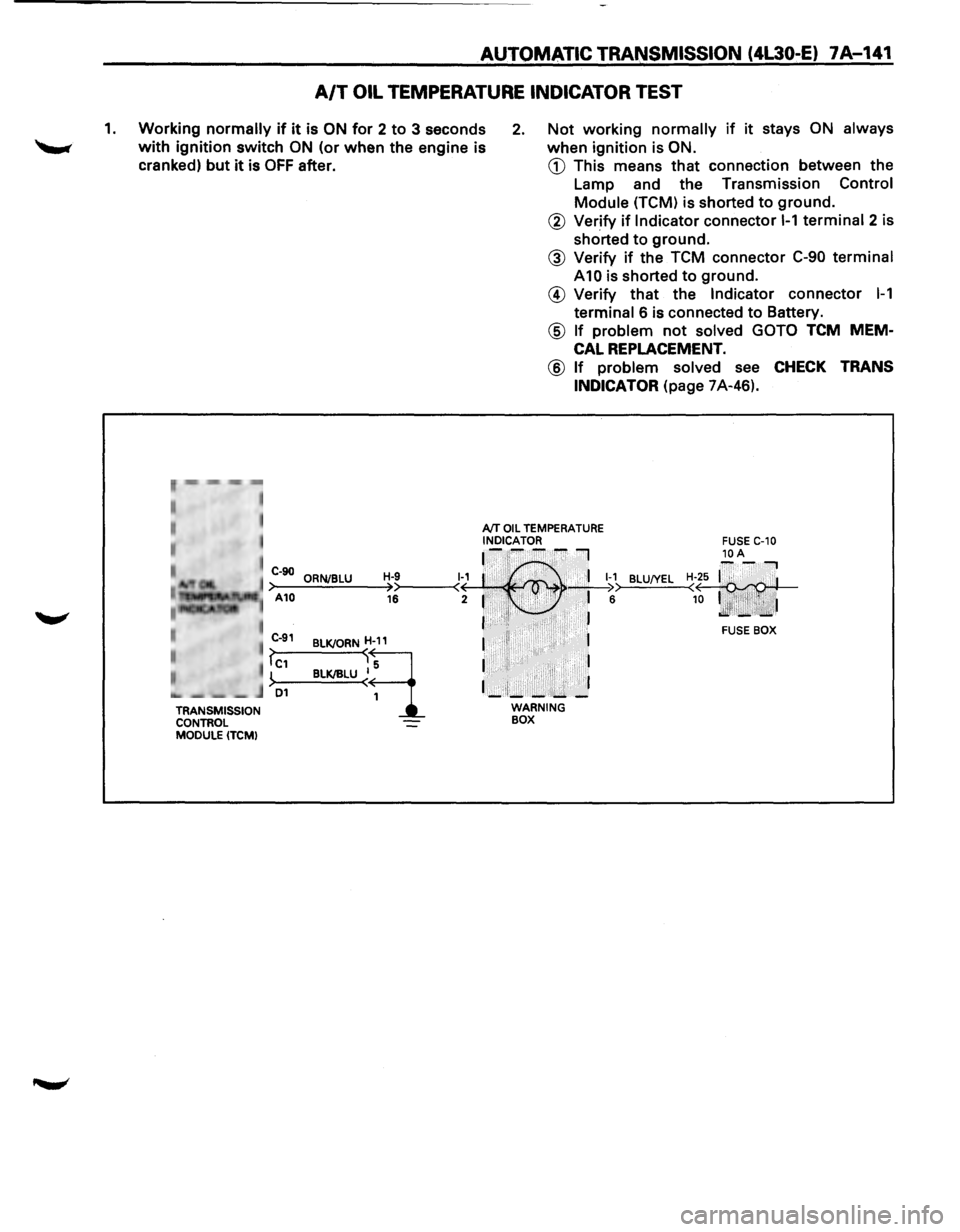
A/T OIL TEMPERATURE INDICATOR TEST
1. Working normally if it is ON for 2 to 3 seconds
with ignition switch ON (or when the engine is
cranked)
but it is OFF after.
2. Not working normally if it stays ON always
when ignition is ON.
CD This means that connection between the
Lamp and the Transmission
Control
Module (TCM) is shorted to ground.
r~,··mm -,-,~
• , I
I
TRANSMISSION
CONTROL
MODULE (TCM)
@ Verify if Indicator connector 1-1 terminal 2 is
shorted
to ground.
@ Verify if the TCM connector C-90 terminal
A10 is shorted to ground.
@ Verify that the Indicator connector 1-1
terminal 6 is connected to Battery.
@ If problem not solved GOTO TCM MEM
CAL REPLACEMENT.
@ If problem solved see CHECK TRANS
INDICATOR
(page 7A-46).
AfT OIL TEMPERATURE INDICATOR ~-~--~I
C-90 ORNJBLU H-9 1~1 :·' ,.· . 'I 1-1 >-A-10--=.:..;.;_;:,=-~>>----<( · , . ' >• • _;__I ;:. 16 2 1 . • .i· ,..:., • 6
I ·•'I• ·. . , . . J
BLU!YEL
BLKJORND
BLK/IILU ~~
I II 1
I I
1_:1;_-:....... _]
WARNING BOX
FUSE BOX
Page 1017 of 1928
AUTOMATIC TRANSMISSION (4L30-E) 7 A-145
TCM PRECAUTONS
The TCM can be damaged by:
(1) The Electrostatic discharge
(2) The short circuit of some terminals to voltage
or to ground.
Electrostatic Discharge Damage Description:
(1) Electronic components used to control systems
are often designed
to carry very low voltage,
and are
very susceptible to damage caused by
electrostatic discharge. It is possible for less
than 100 volts of static electricity to cause
damage
to some electronic components. By
comparison,
it takes as much as 4000 volts for
a person to even feel the zap of a static
discharge.
(2) There are several
ways for a person to become
statically charged. The most common methods
of charging are by friction and induction. An
example
of charging by friction is a person
sliding across a car seat, in
which a charge of
as much as 25,000 volts can build up.
Charging
by induction occurs when a person
with well insulated shoes stands near a highly
charged object and momentarily touches
ground. Charges for the same polarity are
drained off, leaving the person
highly charged
with the opposite polarity. Static charges of
either type can cause damage, therefore, it is
important to use care when handling and
testing electronic components.
NOTICE: To prevent possible Electrostatic
Discharge damage:
(1) Do not touch the TCM connector pins or
soldered components on the TCM circuit
board.
(2) When handling a Mem-Cal (PROM), do not
touch the component leads, and do not
remove integrated circuit from carrier.
(3) Be sure to follow the guidelines listed below if
servicing any of these electronic components:
(4) Do not open the replacement part package
until
it is time to install the part.
(5)
Avoid touching electrical terminals of the part.
(6) Before removing the part from its package,
ground the package to a known good ground
on the vehicle.
(7) Always touch a known good ground before
handling the part. This step should be repeated
before installing
the part if the part has been
handled
while sliding across the seat, while
sitting down from a standing position or while
walking some distance.
INFORMATION ON TCM:
(1) The Transmission Control Module (TCM) is
located in the
driver compartment and is the
control center
of the electronic transmission
control system.
(2) The TCM must be maintained at a temperature
below 185°F (85°C) at all times. This is most
essential if the vehicle is put through a paint
baking process. The
TCM will become in
operative
if its temperature exceeds 85°C
(185°F). Therefore, it is recommended that the
TCM be removed or that temporary insulation
be placed around the
TCM during the time the
vehicle is in a paint oven
or other high
temperature process.
(3) The
TCM is designed to process the various
inputs and then respond by sending the
appropriate electrical signals
to control trans
mission upshift,
downshift, shift feel and
torque converter clutch engagement.
(4) The TCM constantly interprets information
from the various sensors, and controls the
systems
that affect transmission and vehicle
performance. By analyzing operational prob
lems, the
TCM is able to perform a diagnostic
function
by displaying DTC(s) and aid the
technician in making repairs.
PROM/MEM-CAL:
(1) Information for a specific engine and vehicle is
programmed using an integrated circuit called
a Programmable Read-Only
Memory (PROM).
It
is also called a MEM-CAL (Memory Cali
brator). This allows one model of controller to
be used for many different vehicles. The
PROM is located inside the TCM and has
information on the engine, transmission,
calibration., etc. While one
TCM part number
can be used by many vehicle lines, a PROM is
more specific and must be used only with the
right vehicles. For this reason, it is very
important to check the latest parts book and
Service Bulletin
information for the correct part
number when replacing a PROM.
Page 1024 of 1928
•
, cCi" -.J )> I .... N
RELAY
& FUSE BOX
(FL-1, FL-2, FL-3)
THROTTLE BODYASM SPEED SENSOR
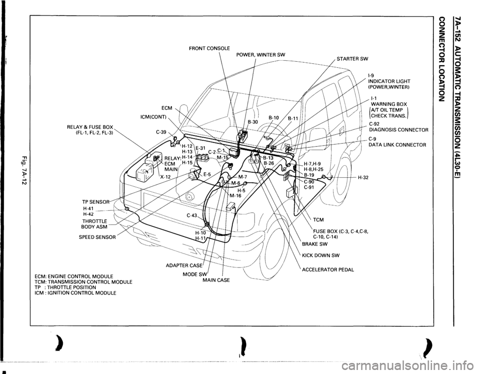
ECM:
ENGINE CONTROL
MODULE
TCM:
TRANSMISSION CONTROL
MODULE
TP :THROTTLE
POSITION
ICM
: IGNITION CONTROL
MODULE
)
ECM
ICM(CONT) FRONT
CONSOLE
MODESW
MAIN
CASE
,}
~H-32
FUSE BOX
(C-3,
C-4,C-8,
C-10,
C-14)
BRAKE
SW
KICK DOWN
SW
ACCELERATOR PEDAL
1-9 INDICATOR LIGHT
(POWER, WINTER) 1-1 WARNING BOX (AfT
OIL
TEMP )
CHECK TRANS.
C-92 DIAGNOSIS CONNECTOR C-9 DATA
LINK CONNECTOR
}
(') 0 2
2 m a ::IJ r-0 (') !4 0 2
" t .... C1l N l> c: a s: !4 n -4 ::IJ l> 2 rA s: c;; rA 0 2 ~ ~ 0 I m
Page 1027 of 1928
... ......,.
AUTOMATIC TRANSMISSION (4L30-E) 7A-155
ON-VEHICLE SERVICE
CHECKING TRANSMISSION FLUID
LEVEL
1. Park the vehicle on level ground.
2. Apply the parking brake.
3. Place the automatic transmission in "Park" and
start the engine.
Allow the engine to idle for
two minutes.
4. With the brakes applied, move the shifter lever
through all the gear ranges, ending in "Park".
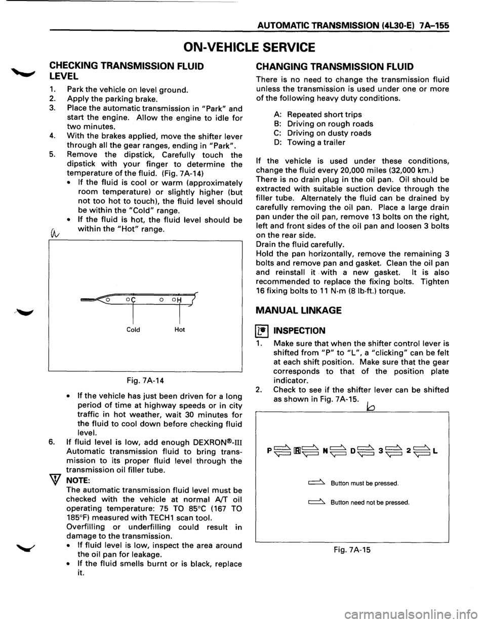
5. Remove the dipstick, Carefully touch the
dipstick with your finger to determine the
temperature of the fluid. (Fig. 7A-14)
• If the fluid is cool or warm (approximately
room temperature) or slightly higher (but
not too hot to touch), the fluid level should
be within the "Cold" range.
• If the fluid is hot, the fluid level should be
(A; within the "Hot" range.
6.
Cold Hot
Fig. 7A-14
• If the vehicle has just been driven for a long
period of time at highway speeds or in city
traffic in hot weather, wait 30 minutes for
the fluid to cool down before checking fluid
level.
If fluid level is low, add enough DEXRON®-m
Automatic transmission fluid to bring trans
mission
to its proper fluid level through the
transmission oil filler tube.
NOTE:
The automatic transmission fluid level must be
checked
with the vehicle at normal AfT oil
operating temperature: 75 TO 85°C (167 TO
185°F)
measured with TECH1 scan tool.
Overfilling or underfilling could result in
damage
to the transmission.
• If fluid level is low, inspect the area around
the oil pan for leakage.
•
If the fluid smells burnt or is black, replace
it.
CHANGING TRANSMISSION FLUID
There is no need to change the transmission fluid
unless the transmission is used under one or more
of the following heavy duty conditions.
A: Repeated
short trips
B: Driving on rough roads
C: Driving on dusty roads
D: Towing a trailer
If the vehicle is used under these conditions,
change the fluid every 20,000 miles (32,000 km.)
There is
no drain plug in the oil pan. Oil should be
extracted
with suitable suction device through the
filler tube. Alternately the fluid can be drained by
carefully removing the oil pan. Place a large drain
pan
under the oil pan, remove 13 bolts on the right,
left and front sides of the oil pan and loosen 3 bolts
on the rear side.
Drain
the fluid carefully.
Hold
the pan horizontally, remove the remaining 3
bolts and remove pan and gasket. Clean the oil pan
and
reinstall it . with a new gasket. It is also
recommended to replace the fixing bolts. Tighten
16 fixing bolts to 11 N·m (8 lb·ft.) torque.
MANUAL LINKAGE
~ INSPECTION
1. Make sure that when the shifter control lever is
shifted
from "P" to "L", a "clicking" can be felt
at each shift position. Make sure that the gear
corresponds
to that of the position plate
indicator.
2. Check to see if the shifter lever can be shifted
as
shown in Fig. 7A-15. jQ
~ Button must be pressed.
~ Button need not be pressed.
Fig. 7A-15
Page 1098 of 1928
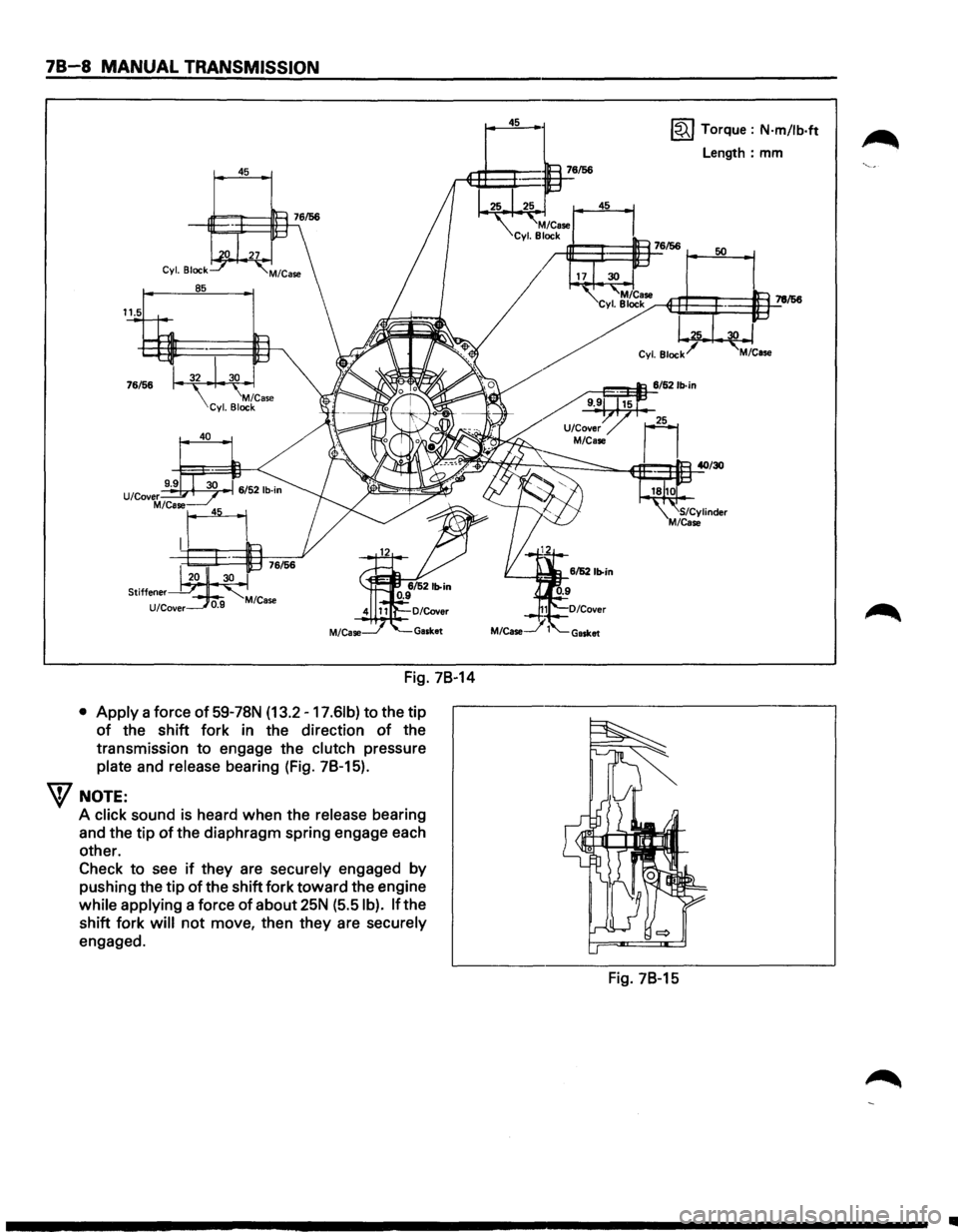
78-8 MANUAL TRANSMISSION
45
Fig. 78-14
• Apply a force of 59-78N (13.2 -17.61b) to the tip
of the shift fork in the direction of the
transmission
to engage the clutch pressure
plate and release bearing (Fig. 78-15).
W NOTE:
A click sound is heard when the release bearing
and the tip
of the diaphragm spring engage each
other.
Check
to see if they are securely engaged by
pushing the tip of the shift fork toward the engine
while applying a force
of about 25N (5.5 I b). If the
shift fork
will not move, then they are securely
engaged.
45 ~ Torque : N·m/lb·ft
Length: mm
Fig. 78-15
..
Page 1124 of 1928
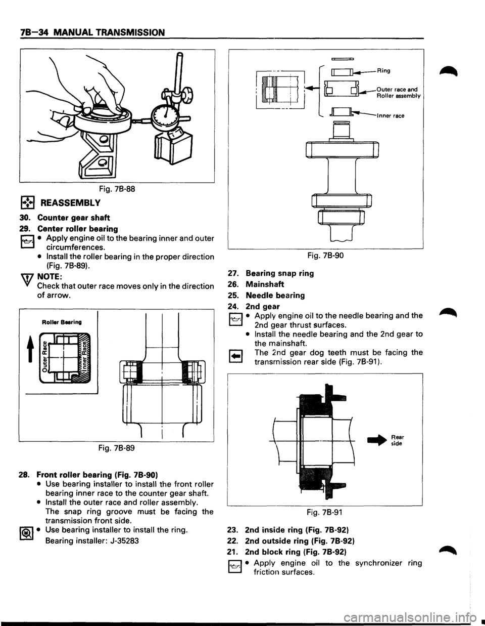
78-34 MANUAL TRANSMISSION
Fig. 78-88
l•!•l REASSEMBLY
30. Counter gear shaft
29. Center roller bearing
r:::::1 • Apply engine oil to the bearing inner and outer
L.:::.l circumferences.
• Install the roller bearing in the proper direction
(Fig. 78-89).
'q7 NOTE:
VI Check that outer race moves only in the direction
of arrow.
Roller Beering
t
Fig. 78-89
28. Front roller bearing (fig. 78-90)
• Use bearing installer to install the front roller
bearing inner race to the counter gear shaft.
• Install the outer race and roller assembly.
The snap ring groove must be facing the
transmission
front side.
1®..1• Use bearing installer to install the ring.
Bearing
installer: J-35283
=
rr=:=n--Ring
~ Outer race and ~Roller assembly
c:::Jb..-lnner race
Fig. 78-90
27. Bearing snap ring
26. Mainshaft
25. Needle bearing
24. 2nd gear
D • Apply engine oil to the needle bearing and the
L.:::.l 2nd gear thrust surfaces.
• Install the needle bearing and the 2nd gear to
the mainshaft.
r:;::] The 2nd gear dog teeth must be facing the
~ transmission rear side (Fig. 78-91 ) .
Fig. 78-91
23. 2nd inside ring (Fig. 78-92)
22. 2nd
outside ring (Fig. 78-92)
21. 2nd
bloc:k ring (Fig. 78-92)
.. Rear
side
D • Apply engine oil to the synchronizer ring
L.:::.l friction surfaces.
•
Page 1127 of 1928
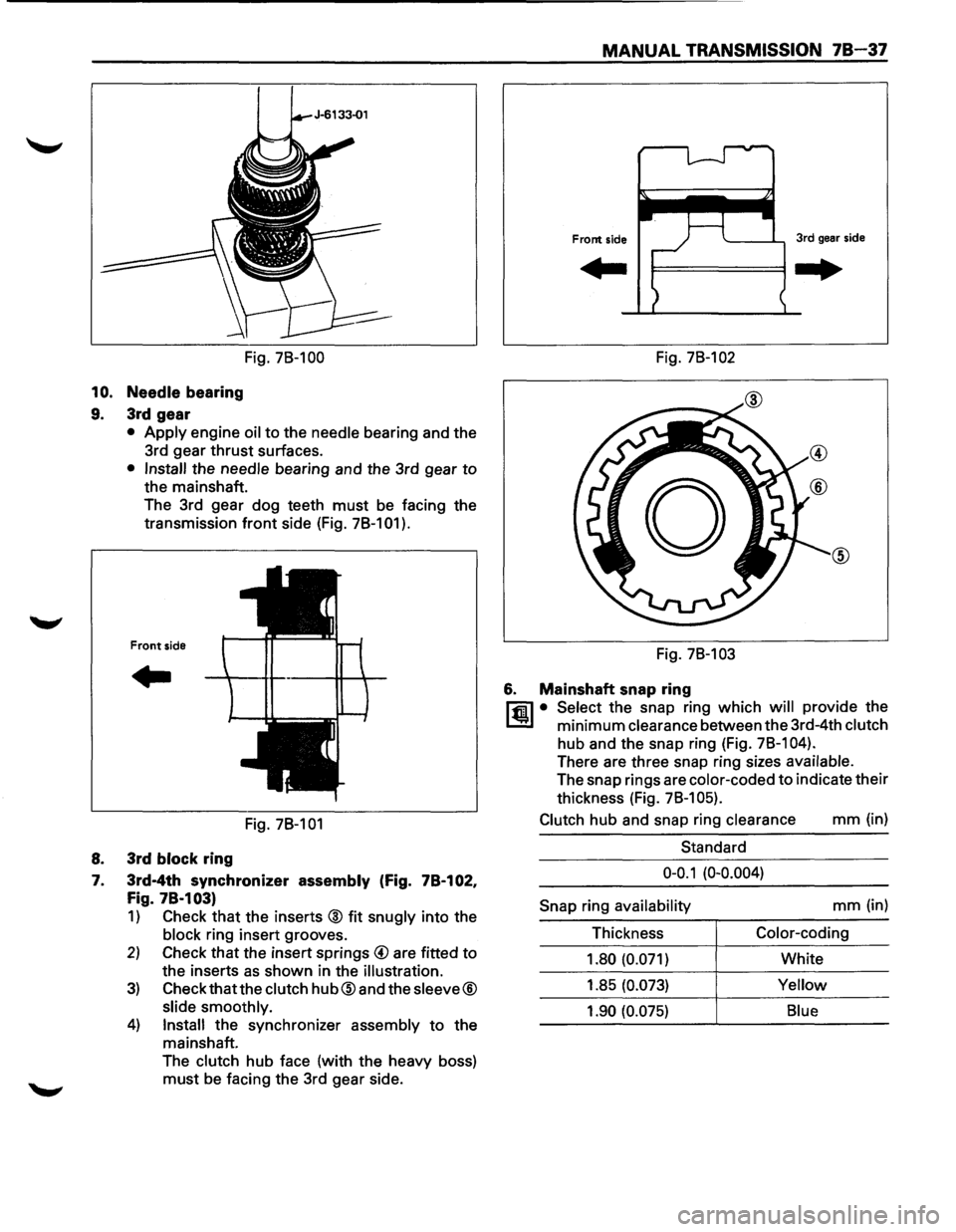
MANUAL TRANSMISSION 78-37
Fig. 78-100 Fig. 78-102
10. Needle bearing
9. 3rd gear
• Apply engine oil to the needle bearing and the
3rd gear
thrust surfaces.
• Install the needle bearing and the 3rd gear to
the mainshaft.
The 3rd gear dog teeth
must be facing the
transmission
front side (Fig. 78-101 ).
Front side
..
Fig. 78-101
8. 3rd block ring
7. 3rd-4th synchronizer assembly (Fig. 78-102,
Fig. 78·103)
1) Check that the inserts @ fit snugly into the
block ring insert grooves.
2) Check that the insert springs @ are fitted to
the inserts as shown in the illustration.
3) Check that the clutch hub@and the sleeve®
slide smoothly.
4) Install the synchronizer assembly to the
mainshaft.
The
clutch hub face (with the heavy boss)
must be facing the 3rd gear side. Fig.
78-103
6. Mainshaft snap ring
l"fil • Select the snap ring which will provide the
l..!l!l minimum clearance between the 3rd-4th clutch
hub and the snap ring (Fig. 78-1 04).
There are three snap ring sizes available.
The snap rings are color-coded to indicate their
thickness (Fig.
78-1 05).
Clutch
hub and snap ring clearance mm (in)
Standard
0-0.1 (0-0.004)
Snap
ring availability mm (in)
Thickness
Color-coding
1.80 (0.071)
White
1.85
(0.073) Yellow
1.90 (0.075) Blue
Page 1139 of 1928
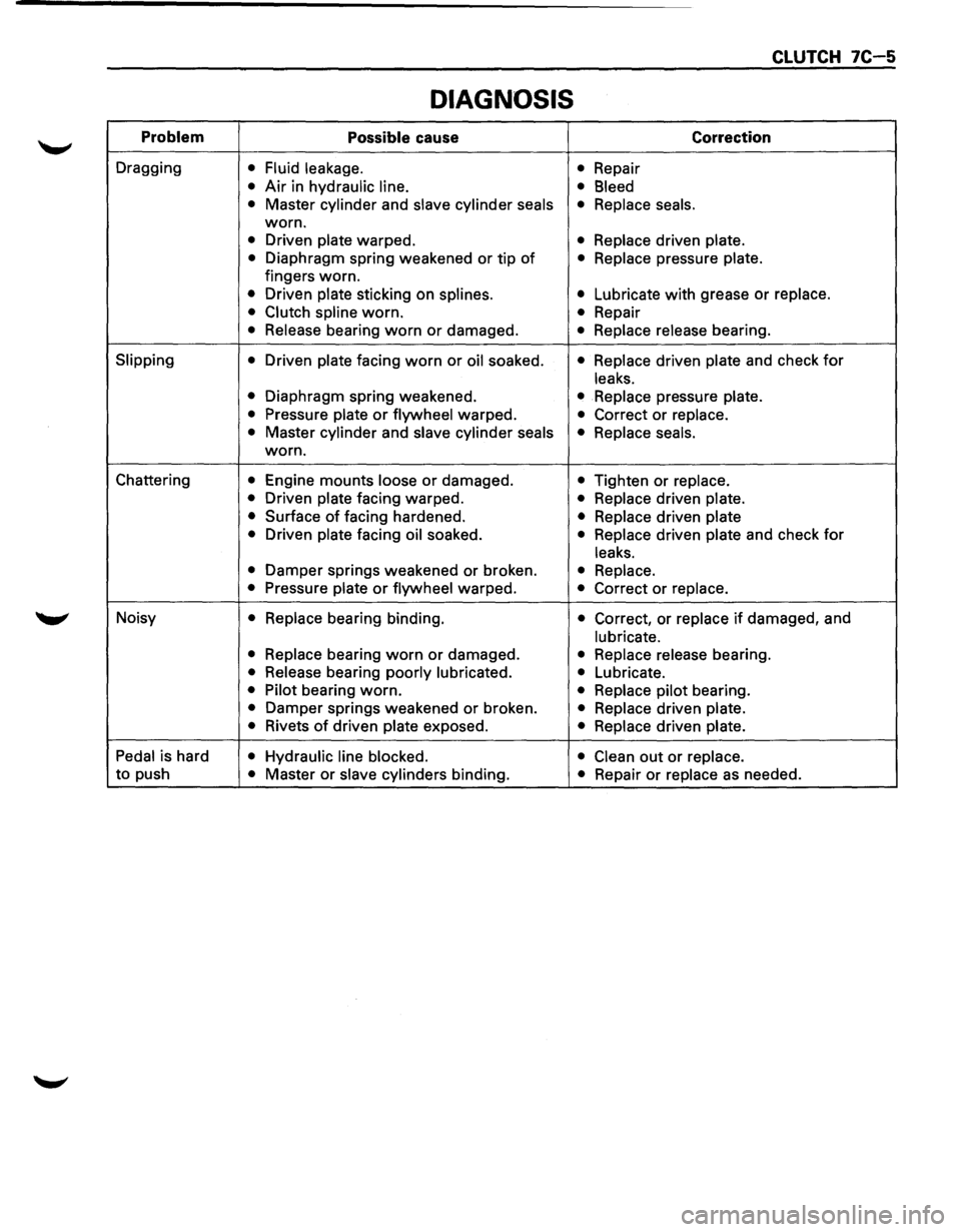
CLUTCH 7C-5
DIAGNOSIS
Problem Possible cause Correction
Dragging • Fluid leakage.
• Repair
• Air in hydraulic line.
• Bleed
•
Master cylinder and slave cylinder seals • Replace seals.
worn.
• Driven plate warped. • Replace driven plate.
•
Diaphragm spring weakened or tip of • Replace pressure plate.
fingers worn.
• Driven plate sticking on splines. • Lubricate with grease or replace.
• Clutch spline
worn. • Repair
• Release bearing worn or damaged. • Replace release bearing.
Slipping
• Driven plate facing worn or oil soaked. • Replace driven plate and check for
leaks.
•
Diaphragm spring weakened. • Replace pressure plate.
•
Pressure plate or flywheel warped. • Correct or replace.
•
Master cylinder and slave cylinder seals
• Replace seals.
worn.
Chattering
• Engine mounts loose or damaged. • Tighten or replace.
•
Driven plate facing warped. • Replace driven plate.
•
Surface of facing hardened. • Replace driven plate
•
Driven plate facing oil soaked. • Replace driven plate and check for
leaks.
•
Damper springs weakened or broken. • Replace.
•
Pressure plate or flywheel warped. • Correct or replace.
Noisy • Replace bearing binding. • Correct, or replace if damaged, and
lubricate.
• Replace
bearing worn or damaged. • Replace release bearing.
• Release bearing poorly lubricated.
• Lubricate.
• Pilot bearing worn. • Replace pilot bearing.
• Damper springs weakened or broken. • Replace driven plate.
•
Rivets of driven plate exposed. • Replace driven plate.
Pedal
is hard • Hydraulic line blocked.
• Clean out or replace.
to push • Master or slave cylinders binding. • Repair or replace as needed.
Page 1149 of 1928
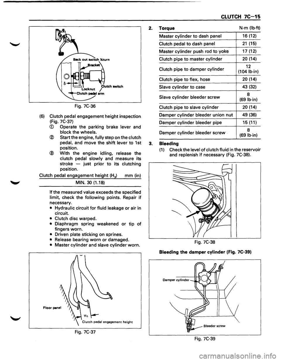
Fig. 7C-36
(6) Clutch pedal engagement height inspection
(Fig.
7C-37)
® Start the engine, fully step on the clutch
pedal,
and move the shift lever to 1st
position.
@ With the engine idling, release the
clutch pedal slowly and measure its
stroke -just prior
to its clutching
position.
Clutch pedal engagement height (H3) mm (in)
MIN. 30 (1.18)
If the
measured value exceeds the specified
limit, check the following points. Repair if
necessary.
• Hydraulic circuit for fluid leakage or air in
circuit.
• Clutch disc warped.
• Diaphragm spring weakened or tip of
fingers worn.
• Driven plate sticking on sprines.
• Release bearing worn or damaged.
• Master cylinder and slave cylinder worn.
Floor panel
Fig. 7C-37
CLUTCH 7C-15
2. Torque N·m (lb·ft)
Master cylinder to dash panel 16 (12)
Clutch pedal to dash panel 21 (15)
Master cylinder push rod to yoke 17 (12)
Clutch pipe to master cylinder 20 (14)
Clutch pipe
to damper cylinder 12
(104 lb·in)
Clutch
pipe to flex, hose 20 (14)
Slave cylinder to case 43 (32)
Slave
cylinder bleeder screw 8 (691b·in)
Clutch
pipe to slave cylinder 20 (14)
Damper cylinder bleeder union nut 49 (36)
Damper cylinder bleeder pipe 15 (11)
Damper cylinder
bleeder screw 8 (69 lb·in)
3. Bleeding
(1) Check
the level of clutch fluid in the reservoir
and
replenish if necessary (Fig. 7C-38).
Fig. 7C-38
Bleeding the damper cylinder (Fig. 7C-39)
Damper cylinder
Fig. 7C-39
Page 1210 of 1928
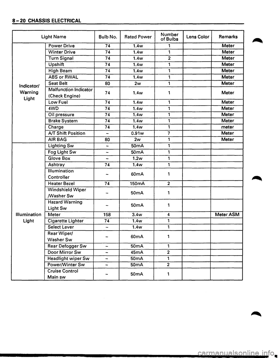
8-20 CHASSIS ELECTRICAL
Light Name Bulb No. Rated Power Number Lens Color Remarks of Bulbs
Power Drive 74 1.4w 1
Meter
Winter Drive 74 1.4w
1 Meter
Turn Signal 74 1.4w 2 Meter
Upshift
74 1.4w 1 Meter
High Beam
74 1.4w 1 Meter
ABSorRWAL 74 1.4w 1 Meter
Indicator/ Seat Belt 80 2w 1 Meter
Warning Malfunction Indicator 74 1.4w
1 Meter
Light (Check
Engine)
Low Fuel 74 1.4w 1 Meter
4WD
74 1.4w 1 Meter
Oil pressure 74 1.4w 1 Meter
Brake System 74 1.4w 1 Meter
Charge 74 1.4w 1
meter
A/T Shift Position -0.91w 7 Meter
AIR BAG 80 2w 1 Meter
Lighting Sw -SOmA 1
Fog Light
Sw -SOmA 1
Glove Box -1.2w 1
Ashtray
74 1.4w 1
Illumination
60mA 1 -Controller
Heater Bezel 74 1SOmA 2
Windshield
Wiper SOmA 1 -/WasherSw
Hazard Warning SOmA 1 -Light Sw
Illumination Meter 158 3.4w 4 MeterASM
Light
Cigarette Lighter
74 1.4w
1
Select Lever -1.4w 1
Rear
Wiper/ 60mA 1 -WasherSw
Rear Defogger Sw -SOmA 1
Door
Mirror Sw -45mA 2
Headlight
wiper Sw -SOmA 1
Power/Winter
Sw -SOmA 2
Cruise Control
SOmA 1 -Main sw
II