check engine ISUZU TROOPER 1995 Workshop Manual
[x] Cancel search | Manufacturer: ISUZU, Model Year: 1995, Model line: TROOPER, Model: ISUZU TROOPER 1995Pages: 1928
Page 995 of 1928
AUTOMATIC TRANSMISSION (4L30-E) 7A-123
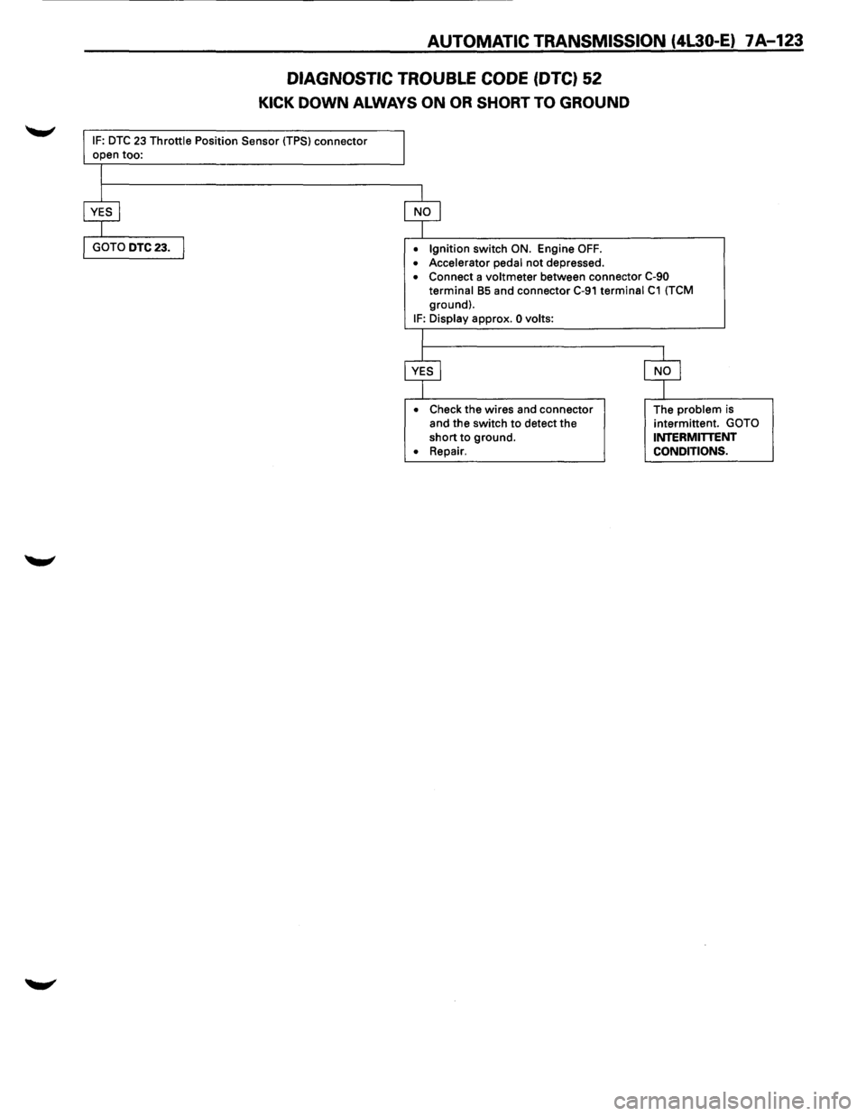
DIAGNOSTIC TROUBLE CODE (DTC) 52
KICK DOWN ALWAYS ON OR SHORT TO GROUND
IF: DTC 23 Throttle Position Sensor (TPS) connector
• Ignition switch ON. Engine OFF.
• Accelerator pedal not depressed. • Connect a voltmeter between connector C-90
terminal B5 and connector C-91 terminal C1 (TCM
ground).
IF: Display approx. 0 volts:
•
Check the wires and connector
and the switch to detect the
short to ground.
• Repair. The
problem is
intermittent. GOTO INTERMITTENT
CONDITIONS.
Page 996 of 1928
7A-124 AUTOMATIC TRANSMISSION (4L30-E)
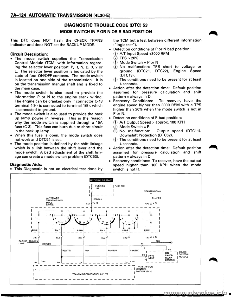
DIAGNOSTIC TROUBLE CODE (DTC) 53
MODE SWITCH IN P OR N OR R BAD POSITION
This DTC does NOT flash the CHECK TRANS
indicator and does NOT set the BACKUP MODE.
Circuit Description:
• The mode switch supplies the Transmission
Control Module (TCM) with information regard
ing
the selector lever position: P, R, N, D, 3, 2 or
L. The selector lever position is indicated by the
state
of four ON/OFF contacts. The mode switch
is located on one side of the transmission. It is
on
the transmission manual shaft and is fixed to
the main case.
• The mode switch is also used to provide the
information P or N to the engine crank wiring.
The engine can be cranked only if connector C-43
terminal 4(H) is connected to terminal 1(E), which
is connected to ground.
• The mode switch is also used to provide the back
up lamp power in reverse. This is the reason
why the mode switch is supplied through a 15A
fuse
(C-3). This fuse can burn due to short circuit
in the back up lamp.
•
When this fuse is open, the mode switch does
not work and DTC54 is set.
• The mode position is defined by the shift linkage
which is a link between the shift lever and the
mode switch. A bad adjustment of the shift link
age can create a mode switch problem (DTC53).
Diagnostic Aids:
• This Diagnostic is not an electrical test done by
the TCM but a test between different information
("logic test").
•
Detection conditions of P or N bad position:
CD A/T Input Speed <3000 RPM
0 TPS > 20%
@ Mode Switch = P or N
® No malfunction: TPS short to voltage or
ground (DTC21, DTC22), Engine Speed
(DTC13).
® The conditions need to be present for at least
4 seconds.
• Action after the detection time: Default position
assumed for pressure calculation and shift
pattern =always in D.
• Recovery Conditions: To recover, have the
engine speed higher than 3000 RPM with a TPS
higher than 20% when the mode switch is not in
PorN.
• Detection conditions of R bad position:
CD A/T Output Speed> approx. 100 KPH
0 Mode Switch= R
@ No malfunction: Output speed (DTC11).
Downshift Protection (DTC62).
® The conditions need to be present for at least
4 seconds.
• Action aft,:H the detection time: Default position
assumed for pressure calculation and shift
pattern = always in D.
• Recovery conditions: To recover, have the output
speed hi~1her than 100 KPH when the mode
switch is not R.
'''·"'·'lllfHJi'.!d'
1
-FUSe C-3 --~ FUSE BOX 16A I I STARTER RELAY
L _____ l I
~~J~Jr'~~~ION RED/BLK BLU/RED
I "'R 2 I R 2J 'R 2 • R 2J I
I '1o N D 3 ~/ l' N D 3 '( D ; / I
:~1-_-_-_~:-~ ~ ~'~t ~-: ~"~\_-_-~-_!!;~= = = ==~-: 2(F) "[ 6(C) 7(B) BIA) 3(G) liE) "'I C-43
BACKUP ( RED/BLU. . BLU ~It
LAMP ~'"""" "'""" "' e>
B4 '-- - -_Q6 - - - -_27 '-- - -_Q4 C-91 4 ~ - - -_co~T~L J
r - - - - - - - - - - - - - - - - - --- -- -1 TRANsM1ss1oN
I ~~~0RL~LITCM) I TRANSMISSION CONTROL INPUTS I
~-----------------------~
•
Page 997 of 1928
AUTOMATIC TRANSMISSION (4l30-E) 7 A-125
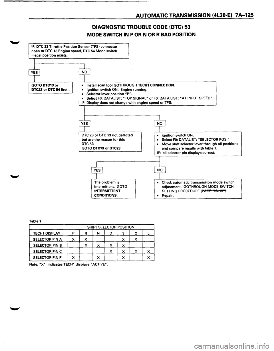
DIAGNOSTIC TROUBLE CODE (DTC) 53
MODE SWITCH IN P OR N OR R BAD POSITION
IF: DTC 23 Throttle Position Sensor (TPS) connector
open or DTC 13 Engine speed, DTC 54 Mode switch
illegal position exists:
Table 1
TECH1 DISPLAY p
SELECTOR PIN A X
SELECTOR PIN B
SELECTOR PIN C
SELECTOR PIN P X
• Install scan tool GOTHROUGH TECH1 CONNECTION.
• Ignition switch ON. Engine running.
• Selector lever position "P". • Select FO: DATALIST: "TOP SIGNAL" or FO: DATA LIST: "AT INPUT SPEED".
IF: Display does not change with engine speed or TPS:
DTC 23 or DTC 13 not detected
but are the reason for this DTC 53.
GOTO DTC13 or DTC23.
R
X
X
The problem is
intermittent. GOTO
INTERMITTENT
CONDITIONS.
SHIFT
SELECTOR POSITION
N D
3
X
X X X
X
X
X X
2 L
X
X X
X
• Ignition switch ON.
• Select FO: DATALIST: "SELECTOR POS.".
• Move shift selector lever through all positions
and compare
results with table 1. IF: all selector pin displays correct:
• Check automatic transmission mode switch
adjustment. GOTHROUGH MODE SWITCH
SETTING PROCEDURE (~. ;"A•1~'Yl
• Repair.
Note:
"X" indicatesTECH1 displays "ACTIVE".
Page 998 of 1928
7A-126 AUTOMATIC TRANSMISSION (4L30-E)
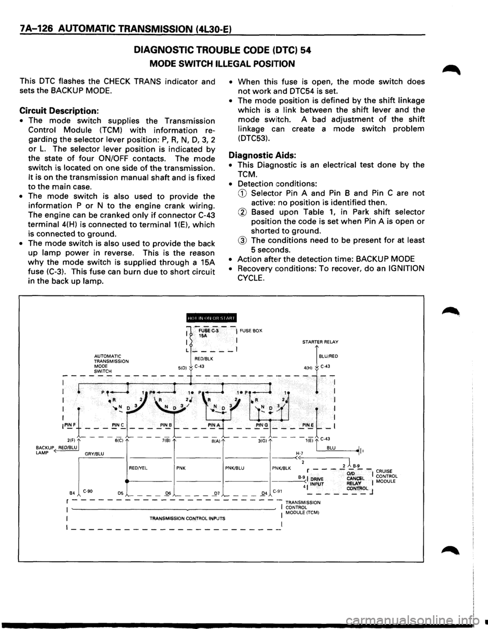
DIAGNOSTIC TROUBLE CODE (DTC) 54
MODE SWITCH ILLEGAL POSITION
This DTC flashes the CHECK TRANS indicator and
sets the BACKUP
MODE.
Circuit Description:
• The mode switch supplies the Transmission
Control Module (TCM) with information re
garding the
selector lever position: P, R, N, D, 3, 2
or L. The selector lever position is indicated by
the state of four ON/OFF contacts. The mode
switch is located on one side of the transmission.
It is on the transmission manual shaft and is fixed
to the main case.
• The mode switch is also used to provide the
information P or N to the engine crank wiring.
The engine can be cranked only if connector C-43
terminal 4(H) is connected to terminal 1(E), which
is connected to ground.
• The mode switch is also used to provide the back
up
lamp power in reverse. This is the reason
why the mode switch is supplied through a 15A
fuse (C-3). This fuse can burn due
to short circuit
in the back
up lamp. •
When
this fuse is open, the mode switch does
not work and DTC54 is set.
• The mode position is defined by the shift linkage
which is a link between the shift lever and the
mode switch. A bad adjustment of the shift
linkage can create a mode switch problem
(DTC53).
Diagnostic Aids:
• This Diagnostic is an electrical test done by the
TCM.
• Detection conditions:
CD Selector Pin A and Pin B and Pin C are not
active: no position is identified then.
@ Based upon Table 1, in Park shift selector
position the code is set when Pin A is open or
shorted to ground.
@ The conditions need to be present for at least
5 seconds.
• Action after the detection time: BACKUP MODE
•
Recovery Gonditions: To recover, do an IGNITION
CYCLE.
ii!Qpi.lifiiUI@ii!ll
•
Page 999 of 1928
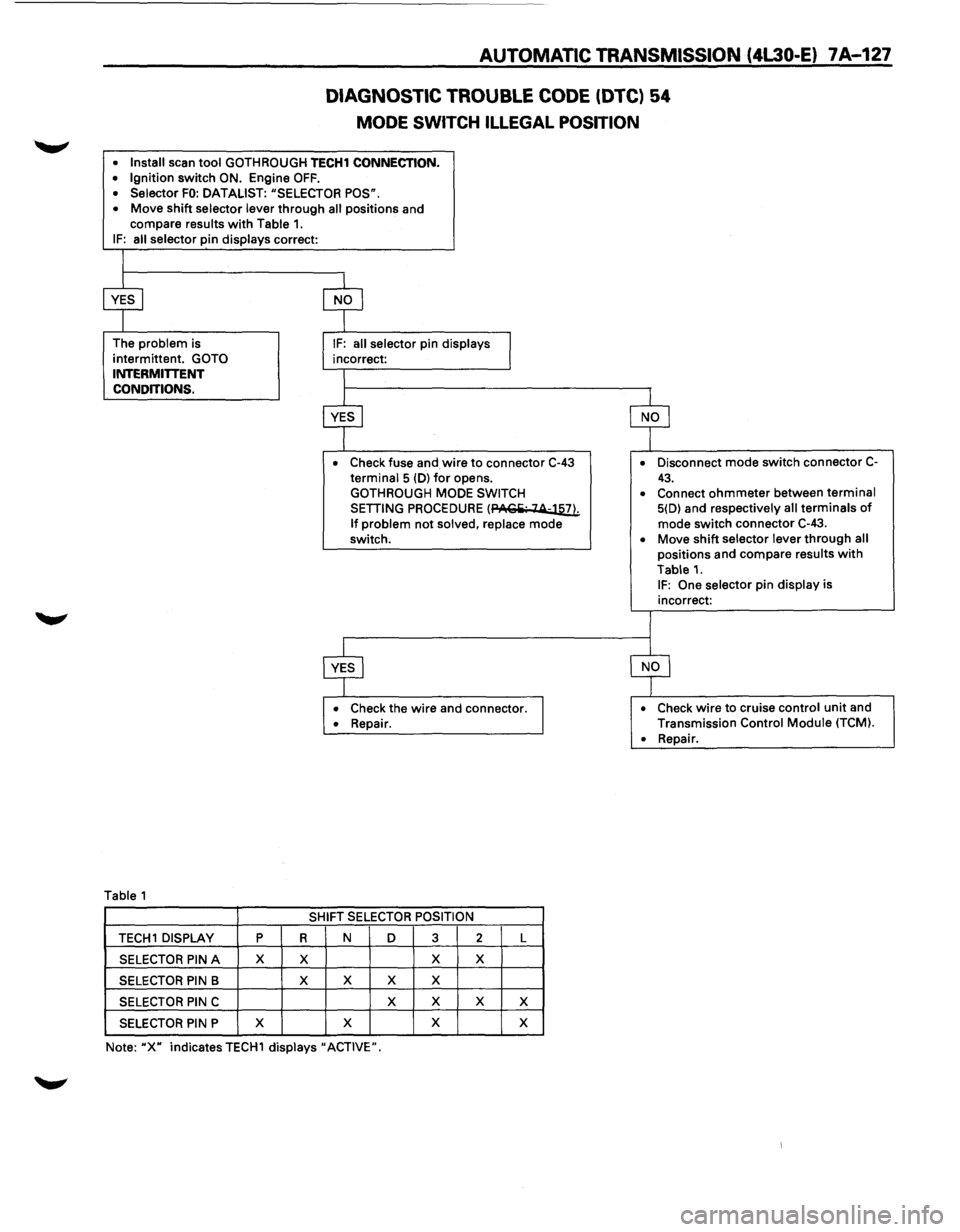
AUTOMATIC TRANSMISSION (4L30-E) 7A-127
DIAGNOSTIC TROUBLE CODE (DTC) 54
MODE SWITCH ILLEGAL POSITION
• Install scan tool GOTH ROUGH TECH1 CONNECTION. • Ignition switch ON. Engine OFF. • Selector FO: DATALIST: "SELECTOR POS".
• Move shift selector lever through all positions and
compare results with Table 1. IF: all selector pin displays correct:
The
problem is
intermittent.
GOTO INTERMITTENT
CONDITIONS.
Table 1
• Check fuse and wire to connector C-43 terminal 5 (D) for opens.
GOTHROUGH MODE SWITCH
SETTING PROCEDURE (PACiii· 14-llli
If problem not solved, replace mode
switch.
• Check the wire and connector. • Repair.
SHIFT SELECTOR POSITION
TECH 1 DISPLAY p R N D 3 2 L
SELECTOR PIN A X X X X
SELECTOR PIN B X
X X X
SELECTOR PIN C X
X X X
SELECTOR PIN P X
X X
X
Note: "X" indicates TECH1 displays" ACTIVE". •
Disconnect
mode switch connector C-
43. • Connect ohmmeter between terminal 5(D) and respectively all terminals of mode switch connector C-43.
• Move shift selector lever through all positions and compare results with
Table 1. IF: One selector pin display is
incorrect:
• Check wire to cruise control unit and
Transmission Control Module (TCM).
•
Repair.
Page 1001 of 1928
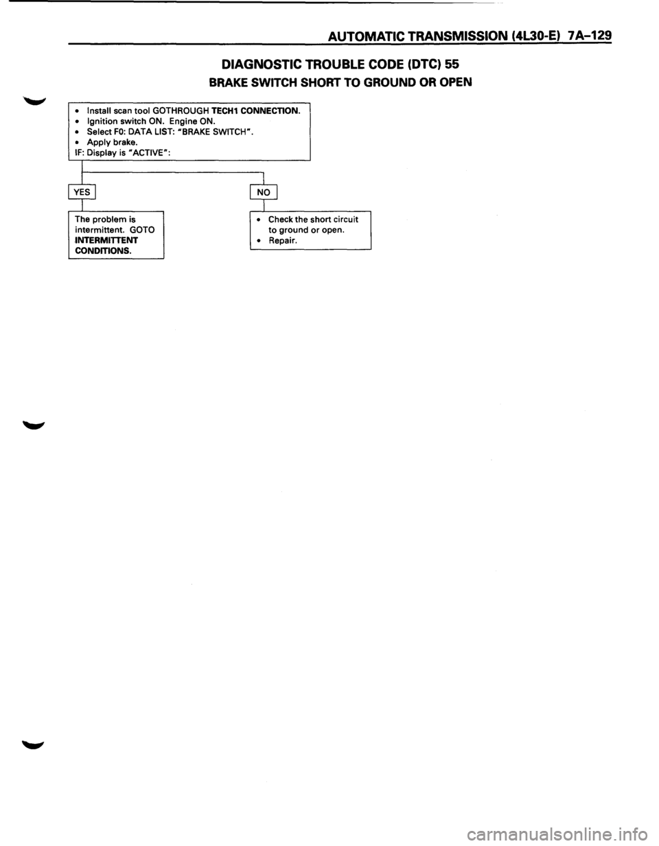
AUTOMATIC TRANSMISSION (4L30-E) 7A-129
DIAGNOSTIC TROUBLE CODE (DTC) 55
BRAKE SWITCH SHORT TO GROUND OR OPEN
• Install scan tool GOTHROUGH TECH1 CONNECTION.
• Ignition switch ON. Engine ON.
• Select FO: DATA LIST: uBRAKE SWITCW.
•
Apply brake. IF: Display is uACTIVE":
The problem is
intermittent.
GOTO
INTERMITTENT
CONDITIONS. •
Check the short circuit to ground or open.
• Repair.
Page 1003 of 1928
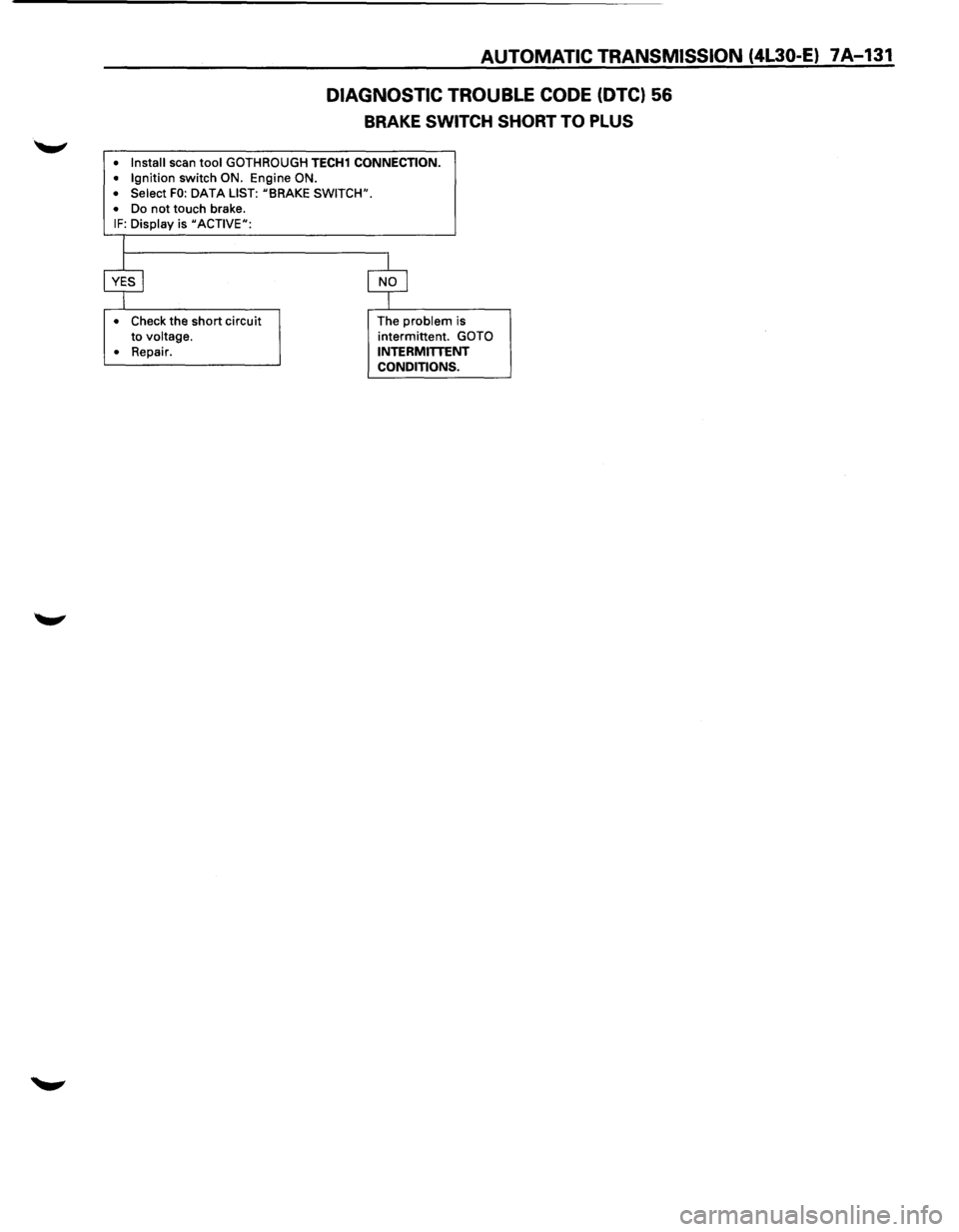
AUTOMATIC TRANSMISSION (4L30-E) 7A-131
DIAGNOSTIC TROUBLE CODE (DTC) 56
BRAKE SWITCH SHORT TO PLUS
• Install scan tool GOTH ROUGH TECH1 CONNECTION.
• Ignition switch ON. Engine ON.
• Select FO: DATA LIST: uBRAKE SWITCH".
•
Do not touch brake. IF: Display is uACTIVEu:
•
Check the short circuit
to voltage.
•
Repair. The
problem is
intermittent. GOTO
INTERMITTENT CONDITIONS.
Page 1004 of 1928
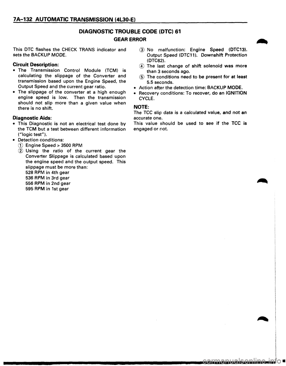
7A-132 AUTOMATIC TRANSMISSION (4L30-E)
DIAGNOSTIC TROUBLE CODE (DTC) 61
GEAR ERROR
This DTC flashes the CHECK TRANS indicator and
sets the BACKUP MODE.
Circuit Description:
• The Transmission Control Module (TCM) is
calculating the slippage of the Converter and
transmission based upon the Engine Speed, the
Output Speed and the current gear ratio.
• The slippage of the converter at a high enough
engine speed is low. Then the transmission
should not slip more than a given value when
there is no shift.
Diagnostic Aids:
• This Diagnostic is not an electrical test done by
the TCM but a test between different information
("logic test").
• Detection conditions:
CD Engine Speed > 3500 RPM
@ Using the ratio of the current gear the
Converter Slippage is calculated based upon
the engine speed and the output speed. This
slippage must be more than:
528
RPM in 4th gear
536 RPM in 3rd gear
556 RPM in 2nd gear
595 RPM in 1st gear
@ No malfunction: Engine Speed (DTC13).
Output Speed (DTC11 ). Downshift Protection
(DTC62).
@ The last change of shift solenoid was more
than 3 seconds ago.
® The conditions need to be present for at least
5.5 seconds.
• Action after the detection time: BACKUP MODE.
•
Recovery conditions: To recover, do an IGNITION
CYCLE.
NOTE:
The TCC slip data is a calculated value, and not an
accurate one.
This value should be used to see if the TCC is
engaged or not.
•
Page 1010 of 1928
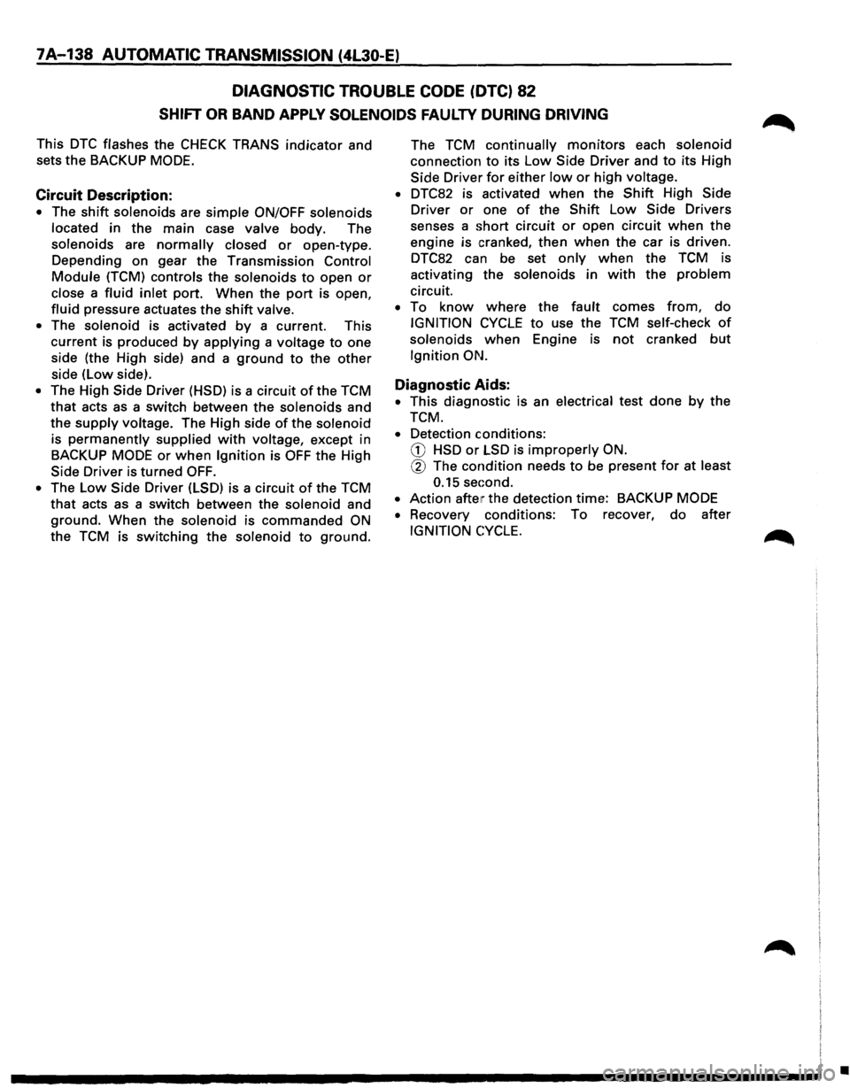
7A-138 AUTOMATIC TRANSMISSION (4L30-E)
DIAGNOSTIC TROUBLE CODE (DTC) 82
SHIFT OR BAND APPLY SOLENOIDS FAULTY DURING DRIVING
This DTC flashes the CHECK TRANS indicator and
sets
the BACKUP MODE.
Circuit Description:
• The shift solenoids are simple ON/OFF solenoids
located in the main case valve body. The
solenoids are
normally closed or open-type.
Depending
on gear the Transmission Control
Module (TCM) controls the solenoids to open or
close a fluid inlet port. When the port is open,
fluid pressure actuates the shift valve.
• The solenoid is activated by a current. This
current is produced by applying a voltage to one
side (the High side) and a
ground to the other
side (low side).
• The High Side Driver (HSD) is a circuit of the TCM
that acts as a switch between the solenoids and
the
supply voltage. The High side of the solenoid
is
permanently supplied with voltage, except in
BACKUP
MODE or when Ignition is OFF the High
Side Driver is turned
OFF.
• The Low Side Driver (LSD) is a circuit of the TCM
that acts as a switch between the solenoid and
ground. When the solenoid is commanded ON
the TCM is switching the solenoid to ground. The
TCM
continually monitors each solenoid
connection
to its Low Side Driver and to its High
Side Driver
for either low or high voltage.
• DTC82 is activated when the Shift High Side
Driver
or one of the Shift Low Side Drivers
senses a
short circuit or open circuit when the
engine is cranked, then when the car is driven.
DTC82 can be set
only when the TCM is
activating the solenoids in
with the problem
circuit.
• To know where the fault comes from, do
IGNITION CYCLE to use the TCM self-check of
solenoids when Engine is not cranked but
Ignition ON.
Diagnostic Aids:
• This diagnostic is an electrical test done by the
TCM.
• Detection conditions:
CD HSD or LSD is improperly ON.
@ The condition needs to be present for at least
0.15 sec:ond.
•
Action after the detection time: BACKUP MODE
•
Recovery conditions: To recover, do after
IGNITION CYCLE.
•
Page 1011 of 1928
AUTOMATIC TRANSMISSION (4L30-E) 7A-139
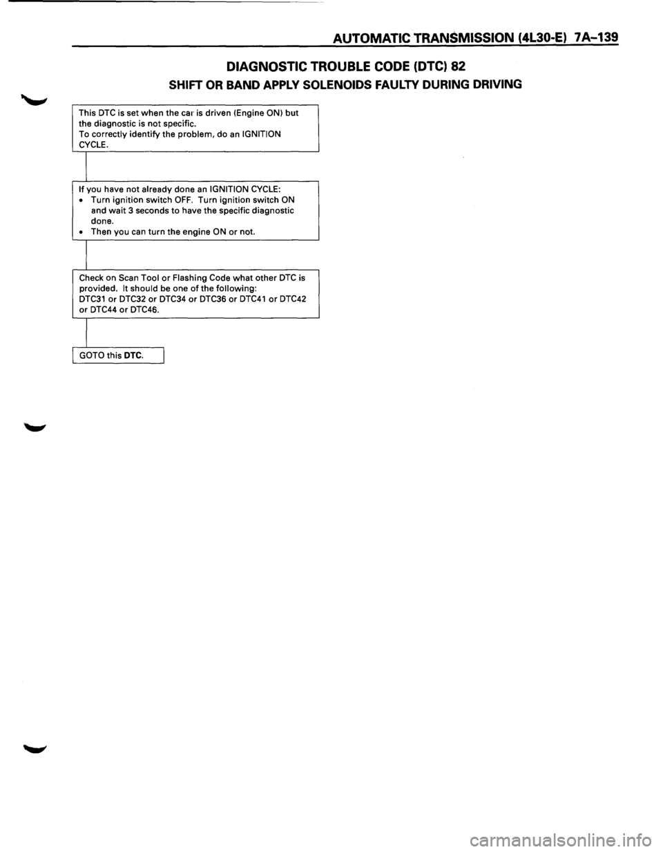
DIAGNOSTIC TROUBLE CODE (DTC) 82
SHIFT OR BAND APPLY SOLENOIDS FAULTY DURING DRIVING
This DTC is set when the car is driven (Engine ON) but the diagnostic is not specific.
To correctly identify the problem, do an IGNITION
CYCLE.
I
If you have not already done an IGNITION CYCLE:
• Turn ignition switch OFF. Turn ignition switch ON
and wait 3 seconds to have the specific diagnostic
done.
• Then you can turn the engine ON or not.
I
Check on Scan Tool or Flashing Code what other DTC is
provided. It should be one of the following: DTC31 or DTC32 or DTC34 or DTC36 or DTC41 or DTC42 or DTC44 or DTC46.
I
GOTO this DTC. I