ignition ISUZU TROOPER 1995 Workshop Manual
[x] Cancel search | Manufacturer: ISUZU, Model Year: 1995, Model line: TROOPER, Model: ISUZU TROOPER 1995Pages: 1928
Page 1383 of 1928
, cE" 00 I I'J w 00
(
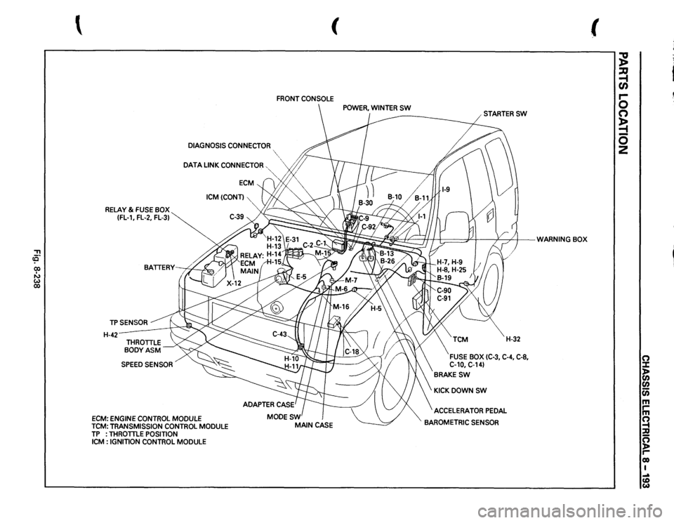
FRONT
CONSOLE
DIAGNOSIS
CONNECTOR
"~",
DATA
LINK
CONNECTOR,
·~
RELAY
& FUSE
BOX
(FL-1,
FL-2,
FL-3)
TPSENSOR H-42-
SPEED
SENSOR
ECM:
ENGINE
CONTROL
MODULE
ICM(CONT)
TCM:
TRANSMISSION
CONTROL
MODULE
TP
: THROTTLE
POSITION
ICM
: IGNITION
CONTROL
MODULE
~;
t I:;::==PI
v
/)
WARNING
BOX
' .
!I
/;;'
H-32
FUSE
BOX
(C-3,
C-4, C-8,
C-10,
C-14)
BRAKESW
KICKDOWNSW ACCELERATOR
PEDAL
BAROMETRIC
SENSOR
(
;g ~ en r-0 (") ~ 0 2
0 :::1: )> (I) (I) c;; m rm ~ :;Q ~ co I .... (D w
Page 1480 of 1928
•
, ce· CX) I w w .....
..
~ m
0
z
0 0 <
m
n
"'
-1
:D
"'
:z:
= ~~ :;; )
O.SIItll 2B
O.&B
ID
-,~
r
-•3
'
.. '
'
' ' IGNITION
CONTROL
MODULECTO
PAGE
S.S1,
531
ECMCASI
(TO PAGE
11-51,
531
TCMihl (TO PAGE
8-1t41
TCMIA111 (TO PAGE
11-1141
~[~} m[i] ~ .:. II
. 0 j[~}l
I'lL,
II"
:----~
.. :~.:,._
:
fill
:~
~~~~ I -··
.!., -
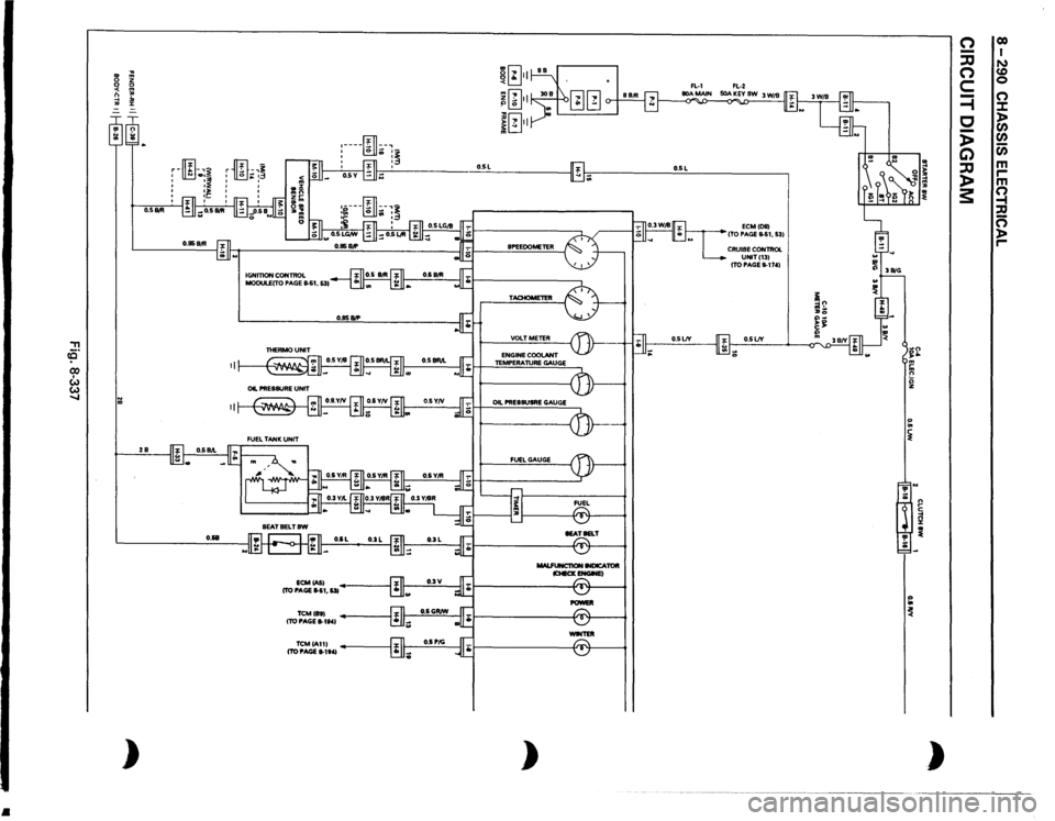
SPEEOOMETER TACHOMETER VOLTMETER ENGINE
COOLANT
TEMPERATURE
GAUGE
OIL PRESSUSRE
GAUGE
FUEL
GAUGE MALFUNCT10N
INDICATOR
lCHECKENGWEI
POWEll -TER
)
O.SL
ECMIDIII
ITO PAGE
11-51,
531
CRUISE
CONTROL UNITI131 ITO PAGE
11-1741
O.SLJY ;;
~ ~ '!' ;;: ~ ~ n ~ ~ )
n -:JJ n c =i c -)> G) :JJ )> 3:
co I N CD 0 (") :.t: > Cl) Cl) Cl) m ,.... m Q , n )> ,....
Page 1484 of 1928
8-294 CHASSIS ELECTRICAL
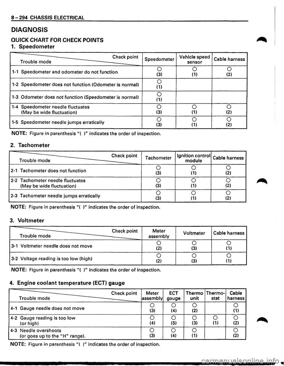
DIAGNOSIS
QUICK CHART FOR CHECK POINTS
1. Speedometer
Trouble mode Check
point
1-1 Speedometer
and odometer do not function
1-2 Speedometer does not function (Odometer is normal)
1-3 Odometer does not function (Speedometer is normal)
1-4 Speedometer needle fluctuates
(May be wide fluctuation)
1-5 Speedometer
needle jumps erratically Speedometer
0 (3)
0 (1)
0 (1)
0 (3)
0 (3)
NOTE: Figure
in parenthesis "( )" indicates the order of inspection.
2. Tachometer
Check point Tachometer Trouble mode
2-1 Tachometer does not function 0 (3)
2-2 Tachometer needle fluctuates 0
(May be wide fluctuation) (3)
2-3 Tachometer needle jumps erratically 0 (3)
NOTE: Figure in parenthesis "( )" indicates the order of inspection.
3. Voltmeter
Check point Meter
Trouble mode
assembly
3-1 Voltmeter needle does not move 0 (2)
3-2 Voltage reading is too low (high) 0 (2)
NOTE: Figure in parenthesis "( )" indicates the order of inspection.
4. Engine coolant temperature (ECT) gauge
Vehicle speed
Cable harness
sensor
0 0 (1) (2)
0
0 (1) (2)
0 0 (1) (2)
Ignition control
Cable harness
module
0 0
(1) (2)
0 0 (1) {2)
0 0 (1) (2)
Voltmeter Cable
harness
0 0 (3) (1)
0
0 (3) (1)
Check point Meter ECT Thermo Thermo-Cable
Trouble mode
assembly gauge unit stat harness
4-1 Gauge needle does not move 0
0 0
0
(3) (4) (2) (1)
4-2 Gauge reading is too low 0 0 0 0 0
(or high) (4) (5) (3) (1) (2)
4-3 Needle overshoots 0 0 0 0
(or goes up to the "H" range). (3) (4) (1) (2)
NOTE: Figure in parenthesis "( )" indicates the order of inspection.
..
Page 1488 of 1928
![ISUZU TROOPER 1995 Workshop Manual 8 -298 CHASSIS ELECTRICAL
Inspection of a waveform by oscilloscope
1. Connect a resistance of 1.3 to 5k ohm (1.4W or more) between the harness side connectors 14[ill
and 8 [ElQ] of the meter.](/img/61/57183/w960_57183-1487.png "ISUZU TROOPER 1995 Workshop Manual 8 -298 CHASSIS ELECTRICAL
Inspection of a waveform by oscilloscope
1. Connect a resistance of 1.3 to 5k ohm (1.4W or more) between the harness side connectors 14[ill
and 8 [ElQ] of the meter.")
8 -298 CHASSIS ELECTRICAL
Inspection of a waveform by oscilloscope
1. Connect a resistance of 1.3 to 5k ohm (1.4W or more) between the harness side connectors 14[ill
and 8 [ElQ] of the meter.
2. Install a speedometer tester.
2. Turn on the starter SW.
3. Check the waveform at the time when the vehicle speed is at 37mph.
I Normal waveform I
ov 4-
A
-
23.6m sec. i
pproximate battery voltage -2V
Max. 2V
Fig. 8-340
2. TACHOMETER
2-1 TACHOMETER DOES NOT FUNCTION
I· IS THE PULSE INPUT NORMAL? l
I
I
I YES I
I
I REPLACE THE TACHOMETER I
I
NO I
I
REPLACE THE IGNITION CONTROL MODULE, OR REPAIR A POOR CONNECTION OF THE CONNECTORS
IN THE CIRCUIT OR A FAILURE IN THE CABLE HARNESS
Page 1628 of 1928
9J-4 Supplemental Restraint System
'"""'t::~h-l--"b~RM PASSENGER SlOE HIGH
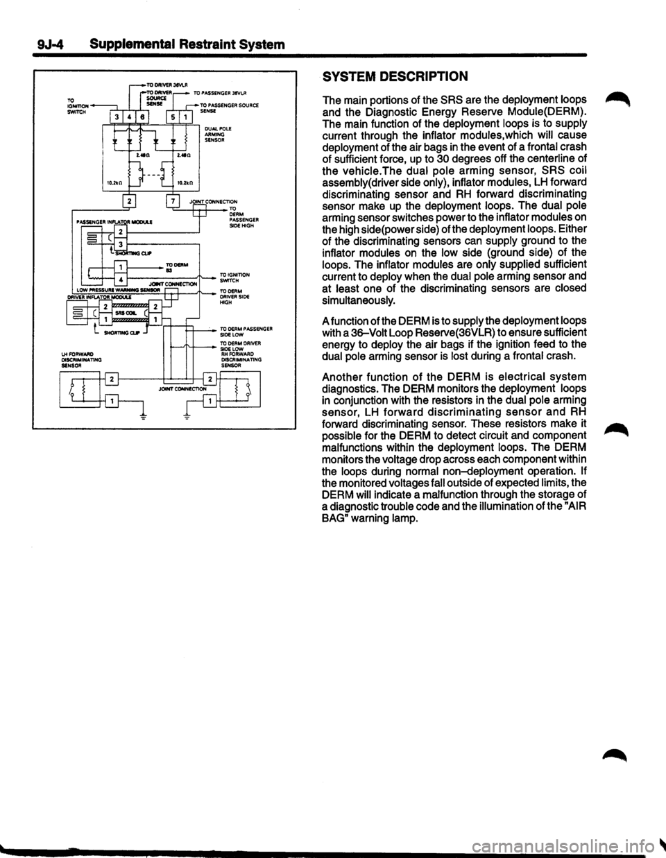
SYSTEM DESCRIPTION
The main portions of the SRS are the deployment loops ~
and the Diagnostic Energy Reserve Module(DERM).
The main function of the deployment loops is to supply
current through the inflator modules,which will cause
deployment of the air bags in the event of a frontal crash
of sufficient force, up to
30 degrees off the centerline of
the vehicle.The dual pole arming sensor, SRS coil
assembly(
driver side only), inflator modules, LH forward
discriminating sensor and
RH forward discriminating
sensor make up the
deployment loops. The dual pole
arming sensor switches power to the inflator modules on
the high side(power side) of the
deployment loops. Either
of the discriminating sensors can
supply ground to the
inflator modules on the low side (ground side) of the
loops. The inflator modules are only supplied sufficient
current to
deploy when the dual pole arming sensor and
at
least one of the discriminating sensors are closed
simultaneously.
A function of the DERM is to supply the deployment loops
with a 36-Volt Loop Reserve(36VLR) to ensure sufficient
energy to
deploy the air bags if the ignition feed to the
dual pole arming sensor is lost during a frontal crash.
Another function of the DERM is electrical system
diagnostics. The DERM monitors the deployment loops
in conjunction with the resistors in the dual pole arming
sensor, LH
forward discriminating sensor and RH
forward discriminating sensor. These resistors make it
possible for the DERM to detect circuit and component
malfunctions within the deployment loops. The DERM
monitors the
voltage drop across each component within
the
loops during normal non-deployment operation. If
the monitored voltages fall outside of expected limits, the
DERM
will indicate a malfunction through the storage of
a diagnostic trouble code and the illumination of the "AIR
BAG"
warning lamp.
Page 1630 of 1928
9J-6 Supplemental Restraint System <
COMPONENT DESCRIPTION
DERM
CAUTION: DO NOT OPEN THE DERM CASE FOR
ANY REASON. TOUCHING THE CONNECTOR PINS
OR SOLDERED COMPONENTS MAY CAUSE
ELECTROSTATIC DISCHARGE DAMAGE. REPAIR
OF A MALFUNCTIONING DERM IS BY
REPLACEMENT ONLY.
The DERM is designed to perform the following functions
in the SRS:
1. Energy Reserve- The DERM maintains two 36-Volt
Loop Reserve(36VLR) energy supplies to provide
deployment energy when the vehicle voltage is low
or lost in a frontal crash.
2. Malfunction Detection-The DERM performs
diagnostic monitoring of SRS electrical components.
3. Malfunction Recording- The DERM provides SRS
diagnostic trouble code information through a scan
tool.
4. Driver Notification- The DERM warns the vehicle
driver of SRS malfunctions by controlling the "AIR
BAG"
warning lamp.
5. Frontal Crash Recording- The DERM records the
SRS status during a frontal crash.
The DERM is connected to the
SRS wiring harness by
a
24-way connector. This harness connector uses a
shorting
clip across certain terminals in the contact area.
This shorting
clip connects the "AIR BAG" warning lamp
to ground when the DERM harness connector is
disconnected. This will cause the "AIR BAG" warning
lamp to come "ON" steady whenever the ignition switch
is at the RUN,BULB
TEST or START positions with the
DERM disconnected.
"AIR BAG"WARNING LAMP
Ignition voltage is applied to the "AIR BAG" warning lamp
when the ignition switch is at the RUN,BULB TEST or
START positions. The DERM controls the lamp by
providing ground with a
lamp driver. The "AIR BAG"
warning lamp is used in the SRS to do the following:
1. Verify lamp and DERM operation by flashing SEVEN
times when the ignition switch is first turned"ON".
2. Warn the vehicle driver of SRS electrical system
malfunctions which could potentially affect the
operation of the
SRS. These malfunctions could
result
in non-deployment in case of a frontal crash
or deployment for conditions less severe than
intended.
The "AIR BAG" warning lamp is the key to driver
notification of SRS malfunctions. For proper lamp
operation, refer to the "SRS Diagnostic System Check"
in this section.
DUAL POLE ARMING SENSOR ~
The dual pole arming sensor is a protective switch
located in the high side(power side) of the deployment
loops.
The dual pole arming sensor is calibrated to close
at low level velocity changes(lower than the
discriminating sensors).
This ensures that the
inflator modules are connected
directly to the "36 VLR" outputs of the DERM or "Ignition
1" voltage
when any discriminating sensor closes.
The dual pole arming sensor consists of: a sensing
element, two sets of normally open switch contacts,
diagnostic resistors and diodes. The sensing
element
closes
both sets of switch contacts when the velocity of
the
vehicle changes at a rate indicating a potential need
for
deployment.
Two of the diagnostic resistors are connected in parallel
with the switch contacts. This allows a small amount of
current to
flow through each of the deployment loops
during normal, non-deployment operation. This current
flow results in voltage drops across each component in
the
deployment loops. The DERM monitor these voltage
drops to detect circuit or component malfunctions. There
are two
additional diagnostic resistors within the dual
pole
arming sensor which allow the DERM to monitor the
voltage supplied to the high side ofthe deployment loops.
These monitored voltages are used by the diagnostic
logic of the DERM to make a more precise determination
of the
actual deployment loop malfunction. ~
The diodes within the dual pole arming sensor provide
isolation between the "36VLR" outputs of the DERM and
the
vehicle electrical system "Ignition 1" voltage. The
presence of the diodes prevents a direct continuity
measurement through the
dual pole arming sensor
resistors to
terminals"3","4" or "5".
DISCRIMINATING SENSORS
The discriminating sensors are protective switches wired
in parallel on the low side(ground side) of the deployment
loops.
These sensors are calibrated to close with velocity
changes which are severe enough to warrant
deployment.
The discriminating sensors consist of a sensing element
and normally open switch contacts when the vehicle
velocity changes are severe enough to warrant
deployment.
A diagnostic resistor is connected in parallel with the
switch contacts within the
LH forward discriminating
sensor and
RH forward discriminating sensor. These
parallel resistors supply the ground path for the current
passing through the
deployment loops during normal,
non-deployment operation. This current flow results in
voltage drops across each component within the
deployment loops. The DERM monitors these voltage
drops to detect circuit or component malfunctions.
II
Page 1632 of 1928
9J-8 Supplemental Restraint System
DEFINITIONS
AIR BAG -An inflatable cloth cushion designed to
deploy in certain frontal crashes. It supplements the
protection offered by the seat belts by distributing the
impact load more evenly over the vehicle occupant's
head and torso.
ASYNCHRONOUS -Performed in a non-periodic
fashion,i.e.no defined time or interval.
B+-Battery voltage, the voltage available at the battery
at the time of the indicated measurement. With the key
"ON" and the engine not running, the system voltage will
likely be between 12 and 12.5 volts. At idle the voltage
may be 14 to 16 volts. The voltage could be as low as 1
0
volts during engine cranking.
BULB
CHECK-The DERM will cause the "AIR BAG"
warning lamp to flash seven times and then go "OFF"
whenever the ignition switch transitions to the RUN
position from any other ignition switch position and no
malfunctions are detected.
"CONTINUOUS MONITORING"-Tests performed by
the DERM on the
SRS every 1 00 milliseconds while
"Ignition
1" voltage is in the normal operating voltage
range at the DERM.
DATA LINK CONNECTOR(DLC)-Formerly "ALDL'', a
connector which allows communication with an
off-board computer, such as a scan
tool.
DATUM LINE-A base line parallel to the plane of the
underbody or frame from which all vertical
measurements originate.
DEPLOY-To inflate the air bag.
DEPLOYMENT
LOOPS - The circuits which supply
current to the inflator modules to deploy the air bag.
DERM -Diagnostic
energy reserve module which
provides reserve energy to the deployment loops and
performs diagnostic monitoring of
all SRS components.
DIAGNOSTIC TROUBLE CODE(DTC) -Formerly
"Code,"a numerical designator used by the DERM to
indicate specific
SRS malfunctions.
DRIVER CURRENT SOURCE-An output of the DERM
which injects current into the driver inflator module circuit
during the "Initiator Assembly Resistance
Test."
DRIVER INFLATOR
MODULE-An assembly located in
the steering wheel hub consisting of an inflatable air bag,
an inflator and an initiator.
DUAL
POLE ARMING SENSOR-A sensor on the high
side(power side) of the deployment loops that is
calibrated to supply voltage to the inflator modules when
the vehicle velocity changes are severe enough to
warrant arming of the air bags in preparation for
deployment.
EEPROM -Electrically Erasable Programmable Read ~
Only Memory. Memory which retains its contents when
power
is removed from the DERM.
FORWARD LH DISCRIMINATING SENSOR-A sensor
on the low side(ground side) of the deployment loops
which is calibrated to ground the inflator modules when
the vehicle velocity changes are severe enough to
warrant deployment of the air bags.
FORWARD RH DISCRIMINATING SENSOR-A sensor
on the low side(ground side) of the deployment loops
which
is calibrated to ground the inflator modules when
the vehicle velocity changes are severe enough
to
warrant deployment of the air bag.
FORWARD LH SENSOR Eng-Room HARNESS-An
assembly of two correct carrying wires which connects
the Forward
LH discriminating sensor to SRS harness.
FORWARD RH SENSOR Eng-Room HARNESS
JUMPER-An assembly of two current carrying wires
which connects the Forward
RH discriminating sensor to
the
SRS harness.
HIGHER PRIORITY FAULT-Each diagnostic trouble
code
is assigned a priority based on the detectability with
other DTCs present. The priority corresponds to the
detectability of the malfunction ONLY, and does NOT
relate to the criticality of the malfunction with respect to ~
deployment or non-deployment under any given
condition.
IGNITION CYCLE -The voltage at the PERM "Ignition
1"
inputs, with ignition switch "ON," is within the normal
operating voltage range for at least ten seconds before
turning ignition switch
"OFF."
IGNITION1
-A battery voltage(B+)circuit which is only
powered with the ignition switch in the RUN,BULB
TEST,or START positions.
INITIATOR-The electrical component inside the inflator
module which, when sufficient current flows, sets off the
chemical reaction that inflates the air bag.
"INITIATOR ASSEMBLY RESISTANCE TEST"-Tests
performed once each ignition cycle when no
malfunctions are detected during "Turn-ON" or
"Continuous Monitoring." This test checks for the correct
DERM configuration for the vehicle, shorts to
"Ignition 1"
in the deployment loops, high resistance or opens in the
"Driver
Side High," "Driver Side Low," "Passenger Side
High"
and "Passenger Side Low" circuits and measures
the resistance of the inflator assembly consisting of: 1)
Initiators, 2) SRS coil assembly(driver side only), 3)
Connectors and associated wiring.
NORMAL OPERATING VOLTAGE RANGE-The ~
voltage measured between the DERM "Ignition 1" ·
terminals and "Ground" terminals is between 7.25 and 16
volts.
•
Page 1633 of 1928
PASSENGER CURRENT SOURCE -An output of the
DERM which injects current into the passenger inflator
module circuit during the
~Initiator Assembly Resistance
'--"" Test."
PASSENGER INFLATOR MODULE -An assembly
located in the right side of the 1/P consisting of an
inflatable bag, an inflator and an initiator.
SCAN TOOL -An off-board computer used to read
diagnostic information from on-board computers via the
data
link connector.
SERIAL DATA -Information representing the status of
the
SRS.
SRS
-Supplemental Restraint System.
SRS COIL ASSEMBLY-An assembly of two current
carrying coils in the driver deployment loop that allows
the rotation of the steering wheel while maintaining the
continuous contact
of the driver deployment loop to the
driver inflator module.
SRS WIRING HARNESS-The wires and connectors
that electrically connect the components in the
SRS.
1 Supplemental Restraint System 9J-9
"10 MINUTE LOOP TEST' -Portions of the "Initiator
Assembly Resistance Test" are repeated every ten
minutes during an ignition cycle. These are the check for
shorts to
"Ignition 1" in the deployment loops and the
check for an open discriminating sensor interconnect
circuit.
''TURN-ON" -Test which the DERM performs on the
SRS once during each ignition cycle immediately after
"Ignition 1" voltage is applied to the DERM and before
"Continuous Monitoring."
36VLR-The 36-volt loop reserve energy supplies from
the DERM which provide deployment power when
vehicle voltage is
low or lost in a frontal crash.
36 VLR DELAY
-Changing of the 36 VLR power supplies
is
inhibited briefly during "Turn-ON." This allows
detection of certain malfunctions related to "Ignition 1"
voltage which cannot be tested with 36 volts present.
Page 1634 of 1928
9J-10 Supplemental Restraint System
DIAGNOSIS
WARNING: TO AVOID DEPLOYMENT WHEN
TROUBLESHOOTING THE SRS, DO NOT USE
ELECTRICAL TEST EQUIPMENT SUCH AS A
BATTERY-POWERED OR AC-POWERED
VOLTMETER,OHMMETER,ETC., OR ANY TYPE OF
ELECTRICAL EQUIPMENT OTHER THAN THAT
SPECIFIED IN THIS MANUAL. DO NOT USE A
NON-POWERED PROBE TYPE TESTER.
INSTRUCTIONS IN THIS MANUAL MUST BE
FOLLOWED CAREFULLY, OTHERWISE PERSONAL
INJURY
MAY RESULT.
DIAGNOSTIC TROUBLE CODES
The "SRS Diagnostic System Check" must always be the
starting point of any SRS diagnosis. The "SRS
Diagnostic System Check" checks for proper" AIR BAG"
warning lamp operation and checks for
SRS diagnostic
trouble codes using the scan
tool.
1. Current diagnostic trouble codes-Malfunctions that
are presently being detected. Current diagnostic
trouble codes are stored
in RAM(Random Access
Memory).
2. History diagnostic trouble codes -All malfunctions
detected since the last time the history memory was
cleared. History diagnostic trouble codes are stored
in EEPROM.
SCAN TOOL DIAGNOSTICS
A scan tool is used to read current and history diagnostic
trouble codes and to clear all diagnostic trouble codes
after a repair is completed. The scan tool must be
updated to communicate with the SRS through a
replaceable cartridge before it can be used for
SRS
diagnostics. To use the scan tool, connect it to the data
link connector and turn the ignition switch
"ON." The scan
tool reads serial data from the DERM
"Serial Data" line
terminal
"A11" to the data link connector terminal "2".
USE OF SPECIAL TOOLS ~
WARNING: TO AVOID DEPLOYMENT WHEN
TROUBLESHOOTING THE SRS, DO NOT USE
ELECTRICAL TEST EQUIPMENT SUCH AS A
BATTERY POWERED
OR AC POWERED
VOLTMETER, OHMMETER, ETC., OR ANY TYPE OF
ELECTRICAL EQUIPMENT OTHER THAN THAT
SPECIFIED IN THIS MANUAL. DO NOT USE A
NON-POWERED PROBE TYPE TESTER.
INSTRUCTIONS IN THIS MANUAL MUST BE
FOLLOWED CAREFULLY, OTHERWISE PERSONAL
INJURY
MAY RESULT. YOU SHOULD BE FAMILIAR
WITH
THE TOOLS LISTED IN THIS SECTION UNDER
THE HEADING SRS SPECIAL TOOLS."
You should be able to measure voltage and resistance.
You should be familiar with proper use of a scan tool such
as the Tech 1 Diagnostic Computer TK-O, SRS
Driver/Passenger Load Tool J-41433, Connector Test
Adapter Kit J-35616-A, and the DVM(Digital
Multimeter)J-39200.
•
Page 1637 of 1928
Supplemental Restraint System 9J-13
ON-VEHICLE SERVICE
SERVICE PRECAUTIONS
WARNING: WHEN PERFORMING SERVICE ON OR
AROUND SRS COMPONENTS OR SRS WIRING,
FOLLOW
THE PROCEDURES LISTED BELOW TO
TEMPORARILY DISABLE THE SRS. FAILURE TO
FOLLOW PROCEDURES COULD RESULT IN
POSSIBLE AIR
BAG DEPLOYMENT, PERSONAL
INJURY OR OTHERWISE
UNNEEDED SRS
REPAIRS.
The DERM in Driver-Passenger SRS can maintain
sufficient voltage to cause a deployment for up to 2
minutes after the ignition switch is turned
"OFF," the
battery is disconnected, or the fuse powering the DERM
is removed.
Many of the service procedures require removal of the
"AIR BAG" fuse, and disconnection of the inflator
modules from the deployment loop to avoid an accidental
deployment.
If the inflator module is disconnected from
the deployment loop as noted in the "Disabling the
SRS"
procedure that follows, service can begin immediately
without waiting for the 2-minute time period to expire.
DISABLING THE SRS
REMOVAL
Turn the ignition switch to "OFF"
1. Remove SRS fuse C-21, C-22, C-23 and C-24 from
left dash side lower fuse block.
2. Disconnect yellow 3-way connector at the base of
steering column.
3. Remove 1/P compartment door assembly, Refer to
"Passenger inflator module replacement" in section
9J-132.
4. Disconnect yellow 4-way connector behind the 1/P
compartment door assembly.
IMPORTANT
• With the "AIR BAG" fuse removed and ignition switch
"ON," if Fuse 21 left. the "AIR BAG" warning lamp will
be "ON." This is normal operation and does not
indicate an
SRS malfunction.
ENABLING THE SRS
INSTALLATION
Turn ignition switch to "LOCK" and remove key.
1. Connect yellow 4-way connector for passenger
inflator module.
2. 1/P compartment door assembly, Refer to
"Passenger inflator module replacemenf' in section
9J-3.
3. Connect yellow 2-way connector at the base of the
steering column.
4. Install "AIR BAG" fuse C-21, C-22, C-23 and C-24 to
left dash side lower fuse block.
Turn ignition switch to
"RUN" and verify that the "AIR
BAG"
warning lamp flashes seven times and then turns
"OFP' If it does not operate as described, perform the
"SRS Diagnostic System Check" in section 9J-2.
HANDLING/INSTALLATION/DIAGNOSIS
1. Inflator modules should not be subjected to
temperatures above
65°C{150°F).
2. Discriminating sensors, inflator modules, arming
sensors, or DERMs should not be used if they have
been dropped from a height
of 91.4 centimeters
{3feet).
3. When a discriminating sensor or arming sensor is
replaced, it must be oriented with the arrow on the
sensor pointing toward the front of the vehicle.
It is
very important for the discriminating sensors and
arming sensor to be located flat on the mounting
surface, parallel to the vehicle datum line.
It is
important that the sensor mounting surface is free of
any dirt or other foreign material.
4. Do not apply power to the SRS unless all
components are connected or a diagnostic chart
requests it, as this
will set a diagnostic trouble code.
5. The "SRS Diagnostic System Check" must be the
starting point of any
SRS diagnostics. The "SRS
Diagnostic System Check" will verify proper "AIR
BAG"
warning lamp operation and will lead you to the
correct chart to diagnose any
SRS malfunctions.
Bypassing these procedures may result
in extended
diagnostic time, incorrect diagnosis, and incorrect
parts replacements.