ignition ISUZU TROOPER 1995 Workshop Manual
[x] Cancel search | Manufacturer: ISUZU, Model Year: 1995, Model line: TROOPER, Model: ISUZU TROOPER 1995Pages: 1928
Page 991 of 1928
AUTOMATIC TRANSMISSION (4L30-E) 7A-119
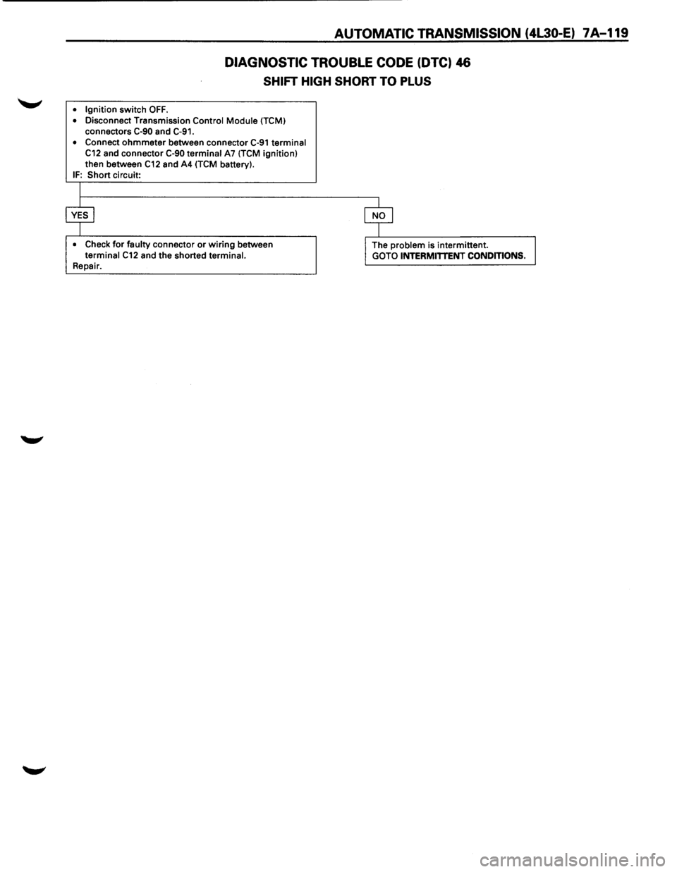
DIAGNOSTIC TROUBLE CODE (DTC) 46
SHIFT HIGH SHORT TO PLUS
• Ignition switch OFF .
• Disconnect Transmission Control Module (TCM) connectors C-90 and C-91.
• Connect ohmmeter between connector C-91 terminal C12 and connector C-90 terminal A7 (TCM ignition)
then between C12 and A4 (TCM battery). IF: Short circuit:
I
$ $
• Check for faulty connector or wiring between I The problem is intermittent. J terminal C12 and the shorted terminal.
GOTO INTERMITTENT CONDITIONS. Repair.
Page 992 of 1928
7A-120 AUTOMATIC TRANSMISSION (4L30-E)
DIAGNOSTIC
TROUBLE CODE (DTC) 51
ENGINE COOLANT SWITCH SHORT TO GROUND, PLUS OR OPEN
This DTC does NOT flash the CHECK TRANS
indicator and does NOT set the BACKUP MODE.
Circuit Description:
• The Engine Coolant Temperature is measured by
a sensor in the coolant system. This information
is used by the Engine Control Module (ECM) for
the engine. The ECM provides the information:
Engine Warm to the Transmission Control
Module (TCM) when the ECM measures a
temperature
higher than 70°C (158°F).
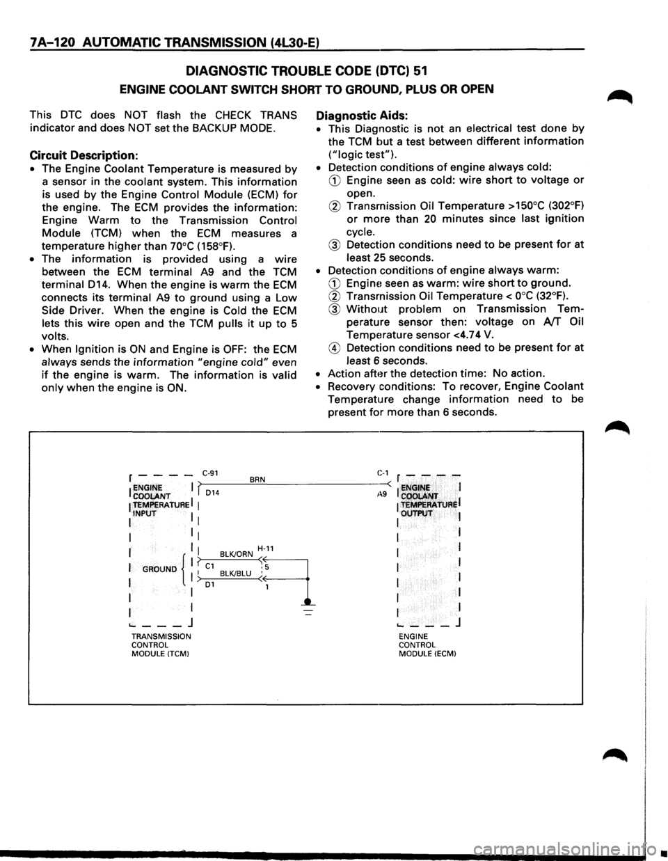
• The information is provided using a wire
between the ECM terminal A9 and the TCM
terminal D14. When the engine is warm the ECM
connects its terminal A9 to ground using a Low
Side Driver. When the engine is Cold the ECM
lets this wire open and the TCM pulls it up to 5
volts.
•
When Ignition is ON and Engine is OFF: the ECM
always sends the information "engine cold" even
if the engine is warm. The information is valid
only when the engine is ON.
Diagnostic Aids:
• This Diagnostic is not an electrical test done by
the TCM but a test between different information
("logic test").
• Detection conditions of engine always cold:
CD Engine! seen as cold: wire short to voltage or
open.
@ Transmission Oil Temperature >150°C (302°F)
or more than 20 minutes since last ignition
cycle.
@ Detection conditions need to be present for at
least 25 seconds.
• Detection conditions of engine always warm:
CD Engine! seen as warm: wire short to ground.
@ Transmission Oil Temperature< ooc (32°F).
@ Without problem on Transmission Tem
perature sensor then:
voltage on AfT Oil
Temperature sensor <4.74 V.
@ Detection conditions need to be present for at
least 6 seconds.
• Action after the detection time: No action.
• Recovery conditions: To recover, Engine Coolant
Temperature change information need to be
present
for more than 6 seconds.
r - - - -C·91 BRN C-1 r - - - -
I ~~~ENT I f,_D_1_4 __ ~.!__--------~-: I ~NGt~~ I
1 teMPERAtuRE I 1
1 t=R'ATJJRel
I INPUT I I I OUTP\:IT l
I 1
1 I I
I I I H-11 I l
I
GROUND 11 ? C1 BLKJORN ~9 I I I I BLKJBLU ( 1 I > o1 I
I I 1 I I
I I I I
~---J ~---J TRANSMISSION ENGINE
CONTROL CONTROL
MODULE
(TCM) MODULE (ECM)
•
Page 993 of 1928
AUTOMATIC TRANSMISSION (4L30-E) 7 A-121
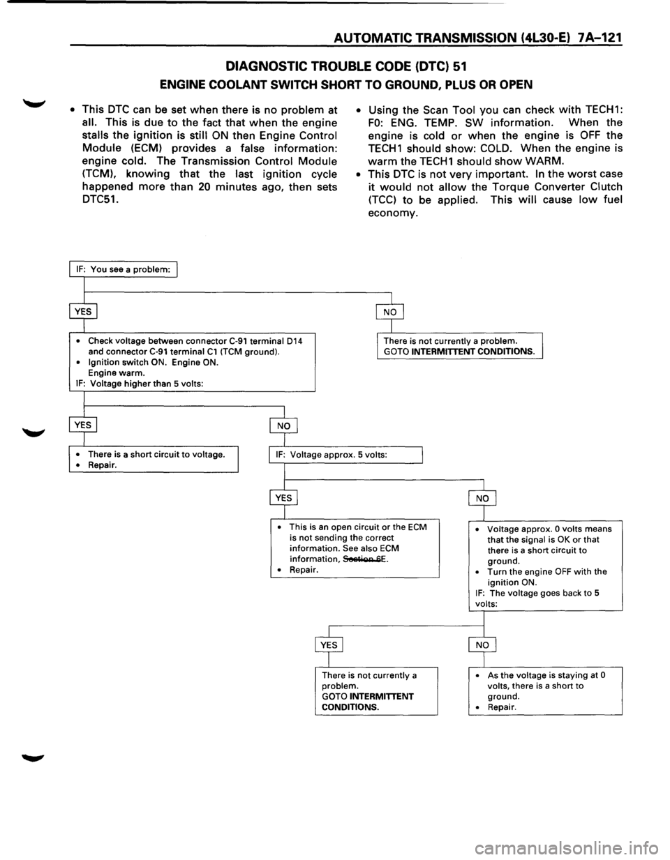
DIAGNOSTIC TROUBLE CODE (DTC) 51
ENGINE COOLANT SWITCH SHORT TO GROUND, PLUS OR OPEN
• This DTC can be set when there is no problem at
all. This is due to the fact that when the engine
stalls the ignition is still ON then Engine Control
Module (ECM) provides a false information:
engine cold. The Transmission Control Module
(TCM), knowing that the last ignition cycle
happened more than 20 minutes ago, then sets
DTC51.
• Check voltage between connector C-91 terminal 014 and connector C-91 terminal C1 (TCM ground). • Ignition switch ON. Engine ON. Engine warm. IF: Voltage higher than 5 volts:
•
There is a short circuit to voltage.
•
Repair.
• Using the Scan Tool you can check with TECH1:
FO: ENG. TEMP. SW information. When the
engine is
cold or when the engine is OFF the
TECH1 should show: COLD. When the engine is
warm the TECH1 should show WARM.
• This DTC is not very important. In the worst case
it would not allow the Torque Converter Clutch
(TCC) to be applied. This will cause low fuel
economy.
There is not currently a problem. GOTO INTERMITTENT CONDITIONS.
• This is an open circuit or the ECM is not sending the correct information. See also ECM information, SeetiQR 6E.
• Voltage approx. 0 volts means that the signal is OK or that
there is a short circuit to ground. • Repair.
There is
not currently a problem. GOTO INTERMITTENT CONDITIONS.
• Turn the engine OFF with the ignition ON. IF: The voltage goes back to 5
volts:
•
As the voltage is staying at 0 volts, there is a short to ground. • Repair.
Page 995 of 1928
AUTOMATIC TRANSMISSION (4L30-E) 7A-123
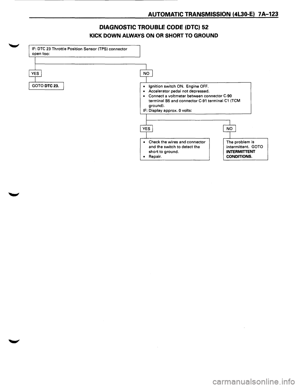
DIAGNOSTIC TROUBLE CODE (DTC) 52
KICK DOWN ALWAYS ON OR SHORT TO GROUND
IF: DTC 23 Throttle Position Sensor (TPS) connector
• Ignition switch ON. Engine OFF.
• Accelerator pedal not depressed. • Connect a voltmeter between connector C-90
terminal B5 and connector C-91 terminal C1 (TCM
ground).
IF: Display approx. 0 volts:
•
Check the wires and connector
and the switch to detect the
short to ground.
• Repair. The
problem is
intermittent. GOTO INTERMITTENT
CONDITIONS.
Page 997 of 1928
AUTOMATIC TRANSMISSION (4l30-E) 7 A-125
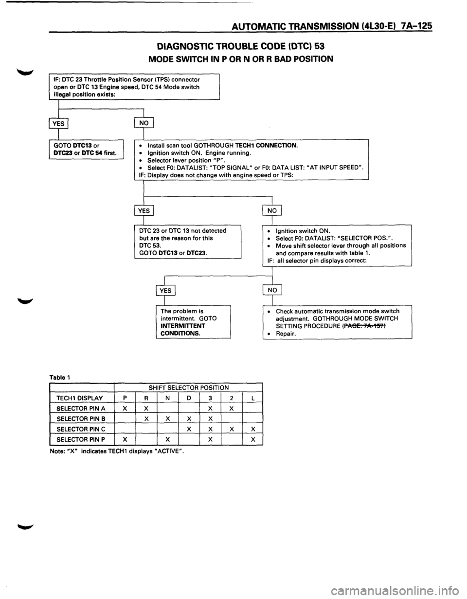
DIAGNOSTIC TROUBLE CODE (DTC) 53
MODE SWITCH IN P OR N OR R BAD POSITION
IF: DTC 23 Throttle Position Sensor (TPS) connector
open or DTC 13 Engine speed, DTC 54 Mode switch
illegal position exists:
Table 1
TECH1 DISPLAY p
SELECTOR PIN A X
SELECTOR PIN B
SELECTOR PIN C
SELECTOR PIN P X
• Install scan tool GOTHROUGH TECH1 CONNECTION.
• Ignition switch ON. Engine running.
• Selector lever position "P". • Select FO: DATALIST: "TOP SIGNAL" or FO: DATA LIST: "AT INPUT SPEED".
IF: Display does not change with engine speed or TPS:
DTC 23 or DTC 13 not detected
but are the reason for this DTC 53.
GOTO DTC13 or DTC23.
R
X
X
The problem is
intermittent. GOTO
INTERMITTENT
CONDITIONS.
SHIFT
SELECTOR POSITION
N D
3
X
X X X
X
X
X X
2 L
X
X X
X
• Ignition switch ON.
• Select FO: DATALIST: "SELECTOR POS.".
• Move shift selector lever through all positions
and compare
results with table 1. IF: all selector pin displays correct:
• Check automatic transmission mode switch
adjustment. GOTHROUGH MODE SWITCH
SETTING PROCEDURE (~. ;"A•1~'Yl
• Repair.
Note:
"X" indicatesTECH1 displays "ACTIVE".
Page 998 of 1928
7A-126 AUTOMATIC TRANSMISSION (4L30-E)
DIAGNOSTIC TROUBLE CODE (DTC) 54
MODE SWITCH ILLEGAL POSITION
This DTC flashes the CHECK TRANS indicator and
sets the BACKUP
MODE.
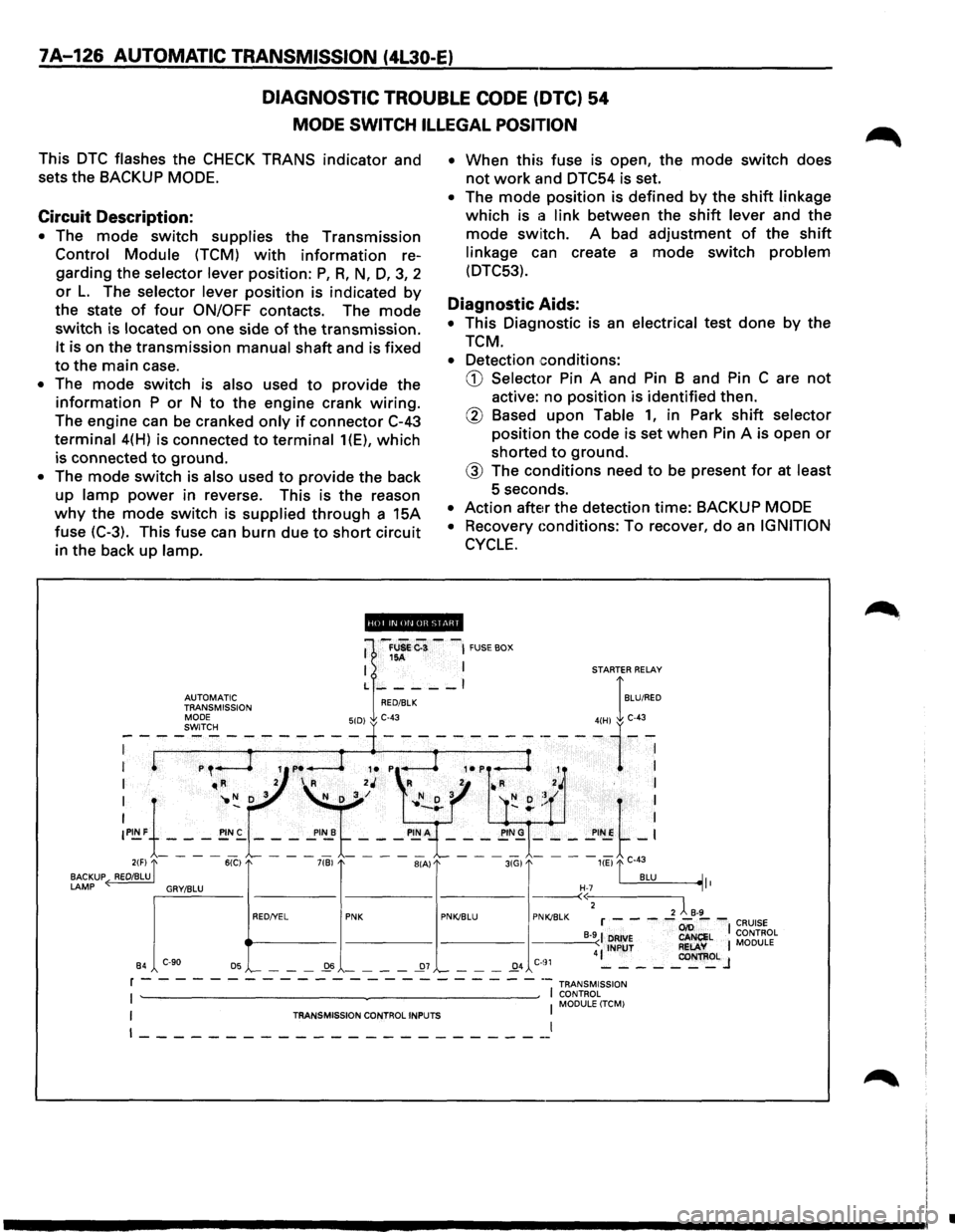
Circuit Description:
• The mode switch supplies the Transmission
Control Module (TCM) with information re
garding the
selector lever position: P, R, N, D, 3, 2
or L. The selector lever position is indicated by
the state of four ON/OFF contacts. The mode
switch is located on one side of the transmission.
It is on the transmission manual shaft and is fixed
to the main case.
• The mode switch is also used to provide the
information P or N to the engine crank wiring.
The engine can be cranked only if connector C-43
terminal 4(H) is connected to terminal 1(E), which
is connected to ground.
• The mode switch is also used to provide the back
up
lamp power in reverse. This is the reason
why the mode switch is supplied through a 15A
fuse (C-3). This fuse can burn due
to short circuit
in the back
up lamp. •
When
this fuse is open, the mode switch does
not work and DTC54 is set.
• The mode position is defined by the shift linkage
which is a link between the shift lever and the
mode switch. A bad adjustment of the shift
linkage can create a mode switch problem
(DTC53).
Diagnostic Aids:
• This Diagnostic is an electrical test done by the
TCM.
• Detection conditions:
CD Selector Pin A and Pin B and Pin C are not
active: no position is identified then.
@ Based upon Table 1, in Park shift selector
position the code is set when Pin A is open or
shorted to ground.
@ The conditions need to be present for at least
5 seconds.
• Action after the detection time: BACKUP MODE
•
Recovery Gonditions: To recover, do an IGNITION
CYCLE.
ii!Qpi.lifiiUI@ii!ll
•
Page 999 of 1928
AUTOMATIC TRANSMISSION (4L30-E) 7A-127
DIAGNOSTIC TROUBLE CODE (DTC) 54
MODE SWITCH ILLEGAL POSITION
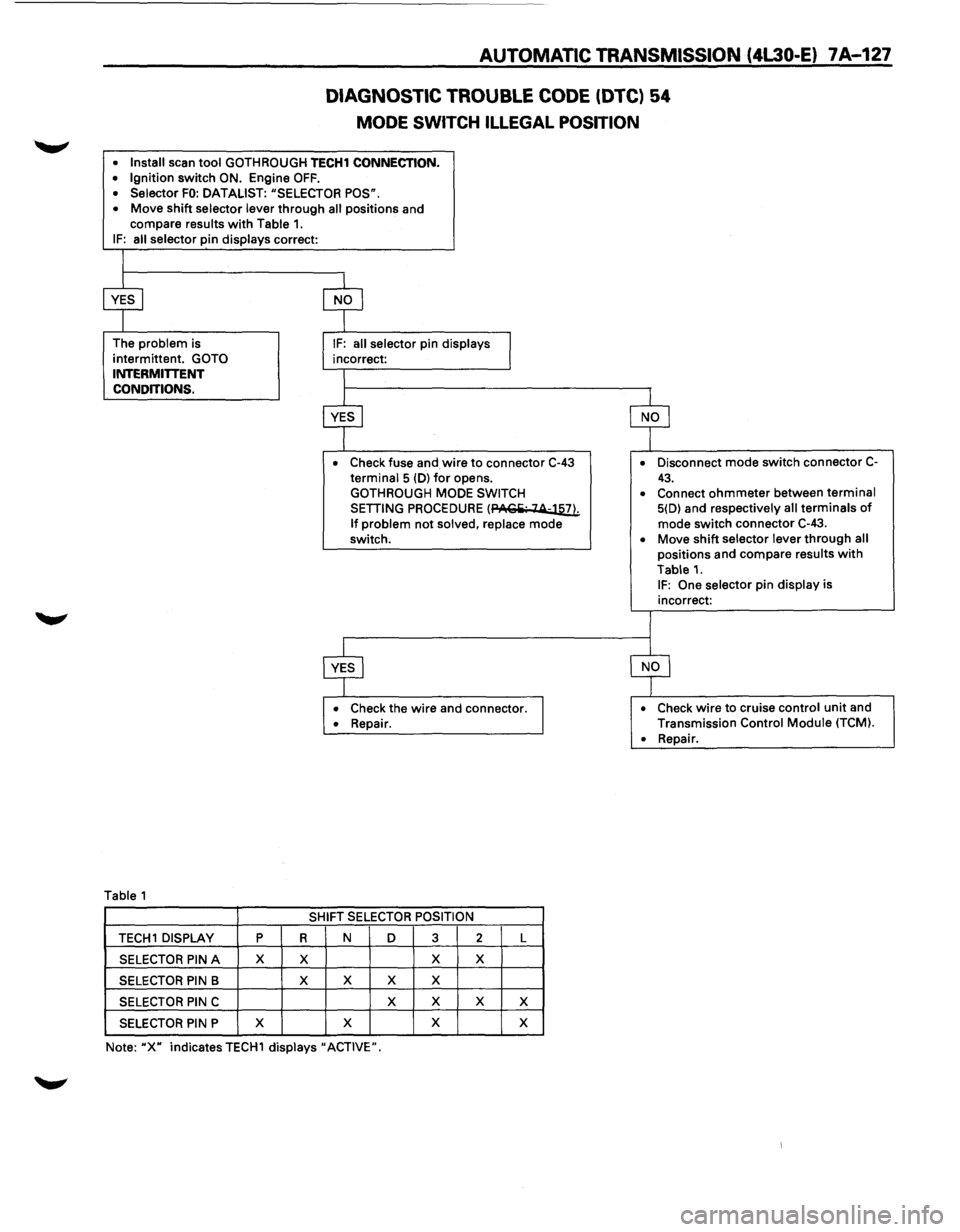
• Install scan tool GOTH ROUGH TECH1 CONNECTION. • Ignition switch ON. Engine OFF. • Selector FO: DATALIST: "SELECTOR POS".
• Move shift selector lever through all positions and
compare results with Table 1. IF: all selector pin displays correct:
The
problem is
intermittent.
GOTO INTERMITTENT
CONDITIONS.
Table 1
• Check fuse and wire to connector C-43 terminal 5 (D) for opens.
GOTHROUGH MODE SWITCH
SETTING PROCEDURE (PACiii· 14-llli
If problem not solved, replace mode
switch.
• Check the wire and connector. • Repair.
SHIFT SELECTOR POSITION
TECH 1 DISPLAY p R N D 3 2 L
SELECTOR PIN A X X X X
SELECTOR PIN B X
X X X
SELECTOR PIN C X
X X X
SELECTOR PIN P X
X X
X
Note: "X" indicates TECH1 displays" ACTIVE". •
Disconnect
mode switch connector C-
43. • Connect ohmmeter between terminal 5(D) and respectively all terminals of mode switch connector C-43.
• Move shift selector lever through all positions and compare results with
Table 1. IF: One selector pin display is
incorrect:
• Check wire to cruise control unit and
Transmission Control Module (TCM).
•
Repair.
Page 1000 of 1928
7A-128 AUTOMATIC TRANSMISSION (4L30-E)
DIAGNOSTIC TROUBLE CODE (DTC) 55
BRAKE SWITCH SHORT TO GROUND OR OPEN
This DTC does NOT flash the CHECK TRANS
indicator and does NOT set the BACKUP MODE.
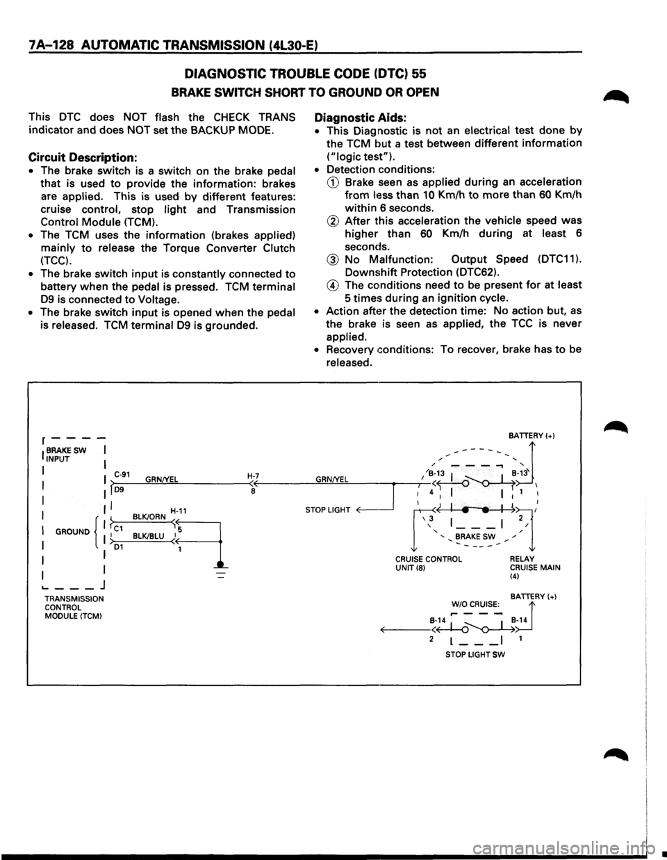
Circuit Description:
• The brake switch is a switch on the brake pedal
that is used to provide the information: brakes
are
applied. This is used by different features:
cruise control, stop
light and Transmission
Control Module (TCM).
•
The TCM uses the information (brakes applied)
mainly to release the Torque Converter Clutch
(TCC).
•
The brake switch input is constantly connected to
battery when the pedal is pressed. TCM terminal
D9 is connected to Voltage.
• The brake switch input is opened when the pedal
is released.
TCM terminal D9 is grounded.
r----
IBRAKESW I INPUT I
I I C-91 GRN/YEL H-7 I >-D9--~~~------~<
I II a
II
I GROUND I C1 I { }
I I >D1
I I
I I ._ ___ j
TRANSMISSION
CONTROL
MODULE (TCM) BLK!ORN
~-11
B~LU~q
Diagnostic
Aids:
• This Diagnostic is not an electrical test done by
the TCM but a test between different information
("logic test").
• Detection conditions:
CD Brake seen as applied during an acceleration
from less than 10 Km/h to more than 60 Km/h
within 6 seconds.
@ After this acceleration the vehicle speed was
higher than 60 Km/h during at least 6
seconds.
@ No Malfunction: Output Speed (DTC11 ).
Downshift Protection (DTC62).
@ The conditions need to be present for at least
5
times during an ignition cycle.
• Action after the detection time: No action but, as
the brake is seen as applied, the TCC is never
applied.
• Recovery conditions: To recover, brake has to be
released.
CRUISE CONTROL UNIT(8) RELAY
CRUISE MAIN (4)
BATTERY(+)
!'~~s:_ d B-14 ~ _ I _B-14 ~--<~~
2 L--_I 1
STOP LIGHT SW
•
Page 1001 of 1928
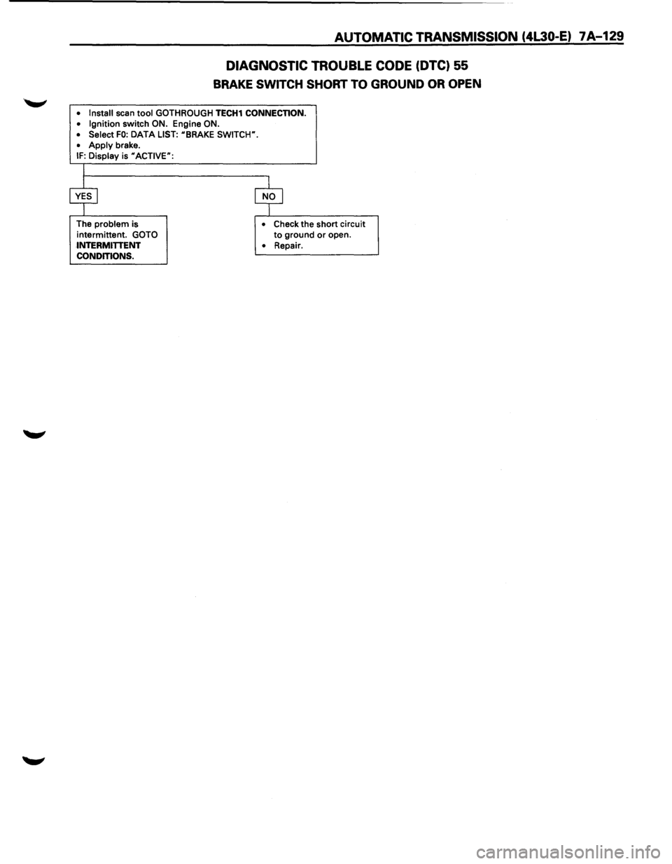
AUTOMATIC TRANSMISSION (4L30-E) 7A-129
DIAGNOSTIC TROUBLE CODE (DTC) 55
BRAKE SWITCH SHORT TO GROUND OR OPEN
• Install scan tool GOTHROUGH TECH1 CONNECTION.
• Ignition switch ON. Engine ON.
• Select FO: DATA LIST: uBRAKE SWITCW.
•
Apply brake. IF: Display is uACTIVE":
The problem is
intermittent.
GOTO
INTERMITTENT
CONDITIONS. •
Check the short circuit to ground or open.
• Repair.
Page 1002 of 1928
7A-130 AUTOMATIC TRANSMISSION (4l30-E)
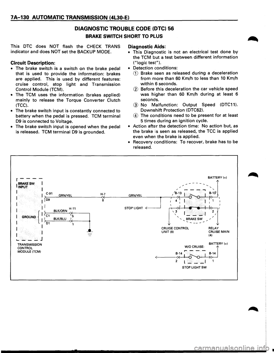
DIAGNOSTIC
TROUBLE CODE (DTC)·56
BRAKE SWITCH SHORT TO PLUS
This DTC does NOT flash the CHECK TRANS
indicator and does
NOT set the BACKUP MODE.
Circuit Description:
• The brake switch is a switch on the brake pedal
that is used to provide the information: brakes
are
applied. This is used by different features:
cruise
control, stop light and Transmission
Control Module (TCM).
•
The TCM uses the information (brakes applied)
mainly to release the Torque Converter Clutch
(TCC).
• The brake switch input is constantly connected to
battery when the pedal is pressed. TCM terminal
D9 is connected to Voltage.
•
The brake switch input is opened when the pedal
is released. TCM terminal D9 is grounded.
r----
IBRAKESW I INPUT I
I I C-91 GRN!YEL H-7 I lf~D-9--~~~------~~
I II I
I GROUND { 1 ?c1 II I >o1
I I
I I
.._ ___ J
TRANSMISSION
CONTROL
MODULE (TCM)
H-11
BLK!ORN sq
BLK!BLU ~
1
Diagnostic Aids:
• This Diagnostic is not an electrical test done by
the TCM but a test between different information
("logic test").
•
Detection conditions:
CD Brake seen as released during a deceleration
from more than 60 Km/h to less than 10 Km/h
within 6 seconds.
® Before this deceleration the car vehicle speed
was
higher than 60 Km/h during at least 6
seconds.
@ No Malfunction: Output Speed (DTC11).
Downshift Protection (DTC62).
@ The conditions need to be present for at least
5 times; during an ignition cycle.
•
Action atte~r the detection time: No action but, as
the brake is seen as released, the TCC is applied
even when the brake is applied.
•
Recovery conditions: To recover, brake has to be
released.
BATTERY(+)
,.------, d / '
GRN/YEL I /~;3 I ~-~3' I
~4 I I 1 I
STOP LIGHT <0---.Jr ~~l/ \3 1 ___ , 2/
' / ' BRAKE SW ,. .......... -----.......
CRUISE CONTROL UNIT(8) RELAY CRUISE MAIN (4)
BATTERY(+)
~~~R~s:_ d
·:.:-: ---~~~-14
2 L--_I 1
STOP LIGHT SW
•