ignition ISUZU TROOPER 1995 Workshop Manual
[x] Cancel search | Manufacturer: ISUZU, Model Year: 1995, Model line: TROOPER, Model: ISUZU TROOPER 1995Pages: 1928
Page 1015 of 1928
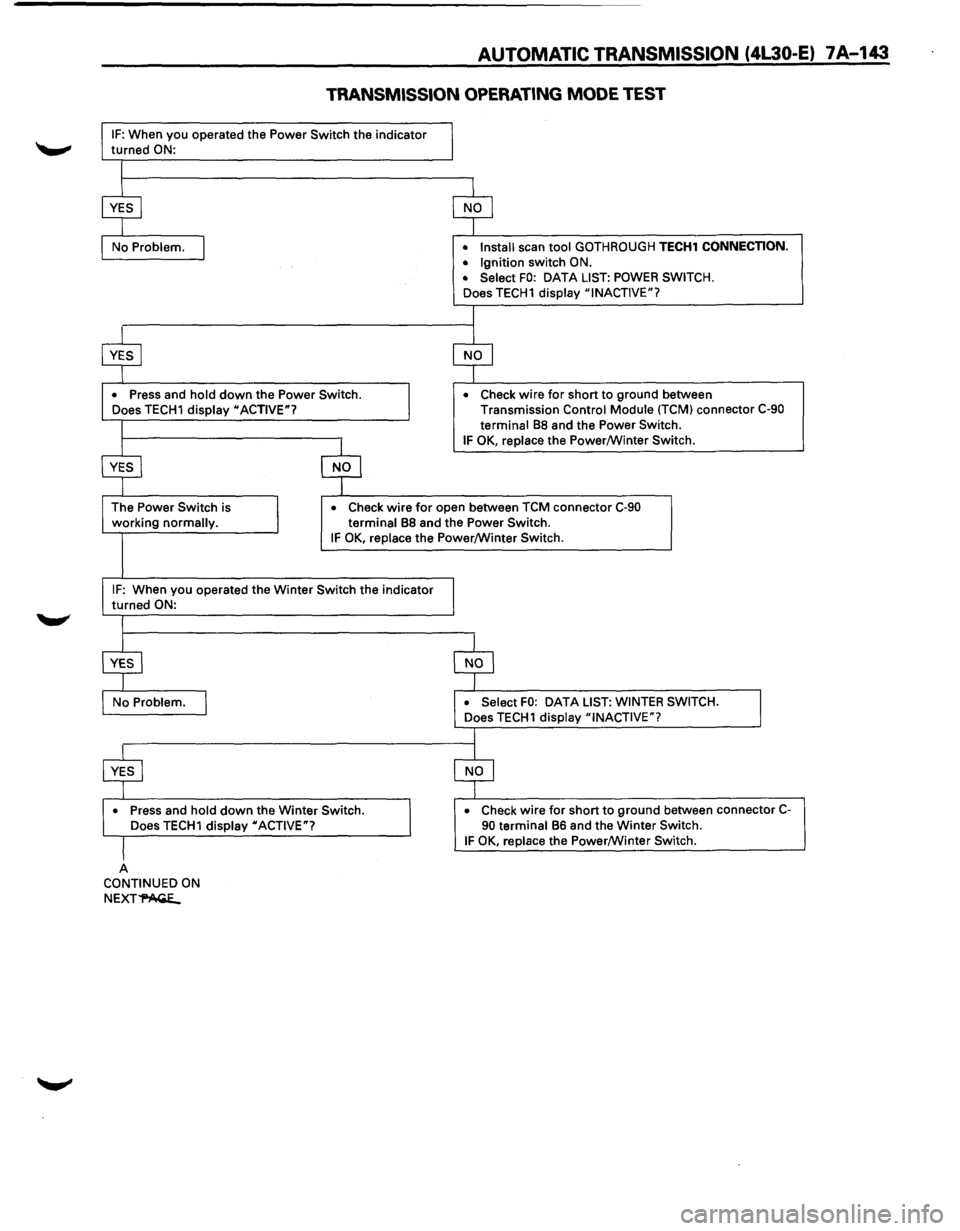
AUTOMATIC TRANSMISSION (4L30-E) 7A-143
TRANSMISSION OPERATING MODE TEST
IF: When you operated the Power Switch the indicator
turned ON:
•
Press and hold down the Power Switch.
Does TECH1 display "ACTIVE"? •
Install
scan tool GOTHROUGH TECH1 CONNECTION.
• Ignition switch ON.
• Select FO: DATA LIST: POWER SWITCH.
Does TECH1 display "INACTIVE"?
•
Check wire for short to ground between
Transmission Control Module (TCM) connector C-90
terminal
88 and the Power Switch.
IF OK, replace the Power/Winter Switch.
working
normally. •
Check wire for open
between TCM connector C-90
terminal 88 and the Power Switch. IF OK, replace the Power/Winter Switch.
IF: When you operated the Winter Switch the indicator
turned ON:
•
Press and hold down the Winter Switch.
Does TECH1 display "ACTIVE"?
A CONTINUED ON
NEXT~
DATA LIST: WINTER SWITCH.
•
Check wire for short to ground between connector C-90 terminal 86 and the Winter Switch. IF OK, replace the Power/Winter Switch.
Page 1016 of 1928
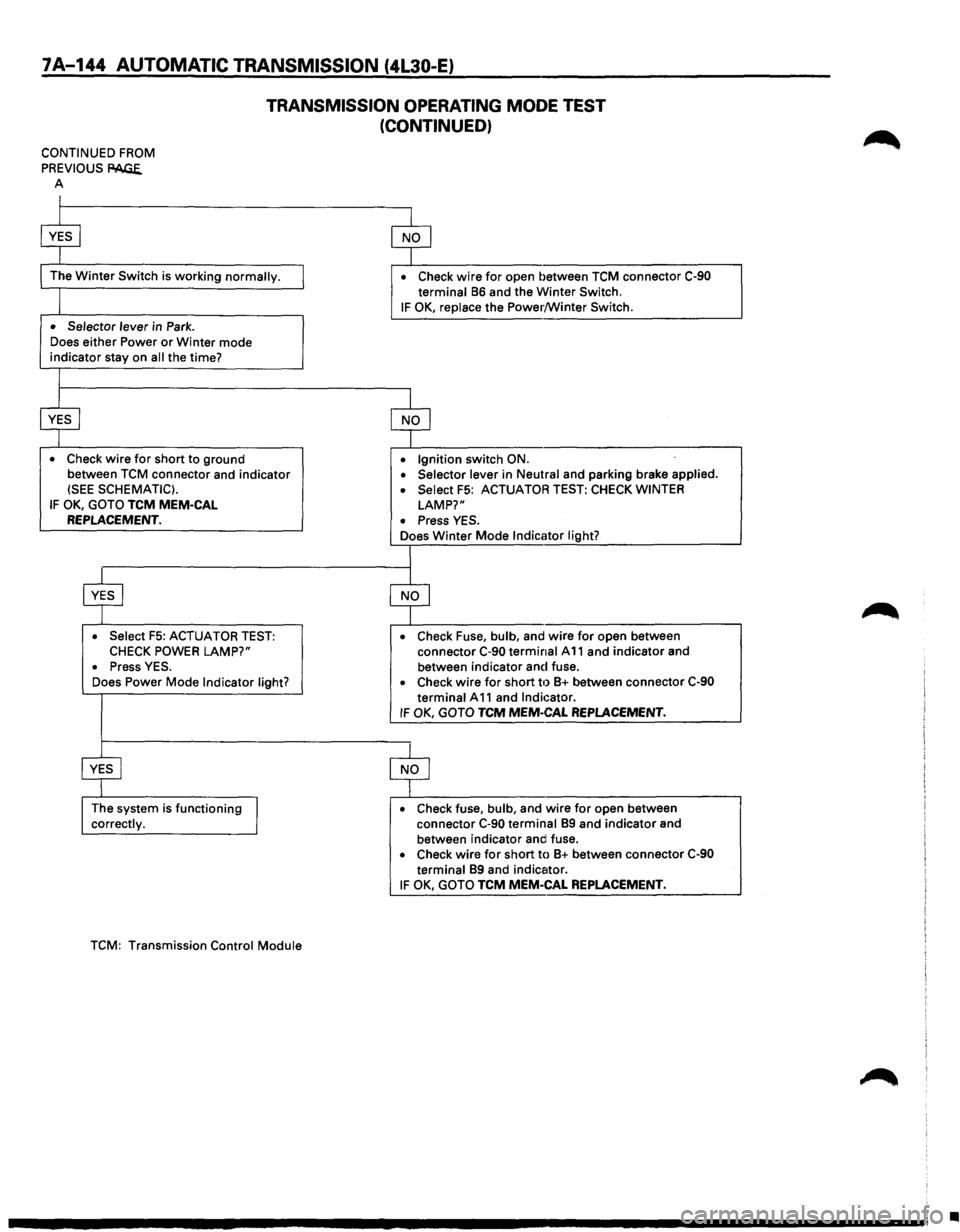
7A-144 AUTOMATIC TRANSMISSION (4L30-E)
TRANSMISSION OPERATING MODE TEST
(CONTINUED)
CONTINUED FROM
PREVIOUS
PAGE. A
I
$
The Winter Switch is working normally.
I
• Selector lever in Park .
Does
either Power or Winter mode indicator stay on all the time?
I
$
• Check wire for short to ground
between
TCM connector and indicator (SEE SCHEMATIC).
IF OK, GOTO TCM MEM-CAL REPLACEMENT.
$
• Select F5: ACTUATOR TEST: CHECK POWER LAMP?"
• Press YES .
Does Power Mode Indicator light?
~
The system is functioning
J correctly.
TCM:
Transmission Control Module
$
• Check wire for open between TCM connector C-90 terminal 86 and the Winter Switch.
IF OK, replace the Power/Winter Switch.
$
• Ignition switch ON .
• Selector lever in Neutral and parking brake applied .
• Select F5: ACTUATOR TEST: CHECK WINTER
LAMP?"
• Press YES .
Does Winter Mode Indicator light?
I
$
• Check Fuse, bulb, and wire for open between
connector C-90 terminal A 11 and indicator and
between indicator and fuse.
• Check wire for short til 8+ between connector C-90
terminal A 11 and Indicator. IF OK, GOTO TCM MEM-CAL REPLACEMENT.
$
• Check fuse, bulb, and wire for open between
connector C-90 terminal 89 and indicator and
between indicator andl fuse.
• Check wire for short to 8+ between connector C-90 terminal 89 and indicator.
IF OK, GOTO TCM MEM-CAL REPLACEMENT.
•
Page 1019 of 1928
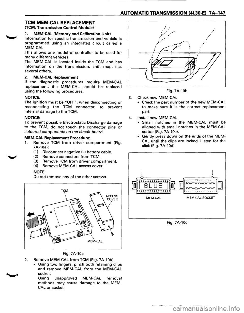
AUTOMATIC TRANSMISSION (4L30-E) 7A-147
TCM MEM-CAL REPLACEMENT
(TCM: Transmission Control Module)
1. MEM-CAL (Memory and Calibration Unit)
Information for specific transmission and vehicle is
programmed using an integrated circuit called a
MEM-CAL.
This allows one model of controller to be used for
many different vehicles.
The MEM-CAL is located inside the TCM and has
information on the transmission, shift map, etc.
several others.
2. MEM-CAL Replacement
If the diagnostic procedures require MEM-CAL
replacement,
the MEM-CAL should be replaced
using the following procedures.
NOTICE:
The ignition must be "OFF", when disconnecting or
reconnecting the TCM connector, to prevent
internal damage to the TCM.
NOTICE:
To prevent possible Electrostatic Discharge damage
to the TCM, do not touch the connector pins or
soldered components on the circuit board.
MEM-CAL Replacement Procedure:
1. Remove TCM from driver compartment (Fig.
7A-10a):
( 1) Disconnect negative (-) battery cable.
(2) Remove connectors from TCM.
(3) Remove TCM from driver compartment.
(4) Remove MEM-CAL access cover.
NOTE:
Do not remove any of the other screws.
Fig.
7A-10a
2. Remove MEM-CAL from TCM (Fig. 7A-10b).
•
Using two fingers, pinch both retaining clips
and remove MEM-CAL from the MEM-CAL
socket.
Using unapproved
methods may cause
CAL or socket.
MEM-CAL removal
damage to the MEM- Fig.
7A-10b
3. Check new MEM-CAL
• Check
the part number of the new MEM-CAL
to make sure it is the correct replacement
part.
4. Install new MEM-CAL
• Small notches in the MEM-CAL must be
aligned with small notches in the MEM-CAL
socket (Fig.
7A-10c).
• Gently
press down on the ends of the MEM
CAL
until the clips are locked. Listen for the
click (Fig. 7A-10d).
! !
($I~rn~ ~~~) . . . . . . . . . . . . . . . ............ .
MEM-CAL MEM-CAL SOCKET
Fig. 7A-10c
Page 1020 of 1928
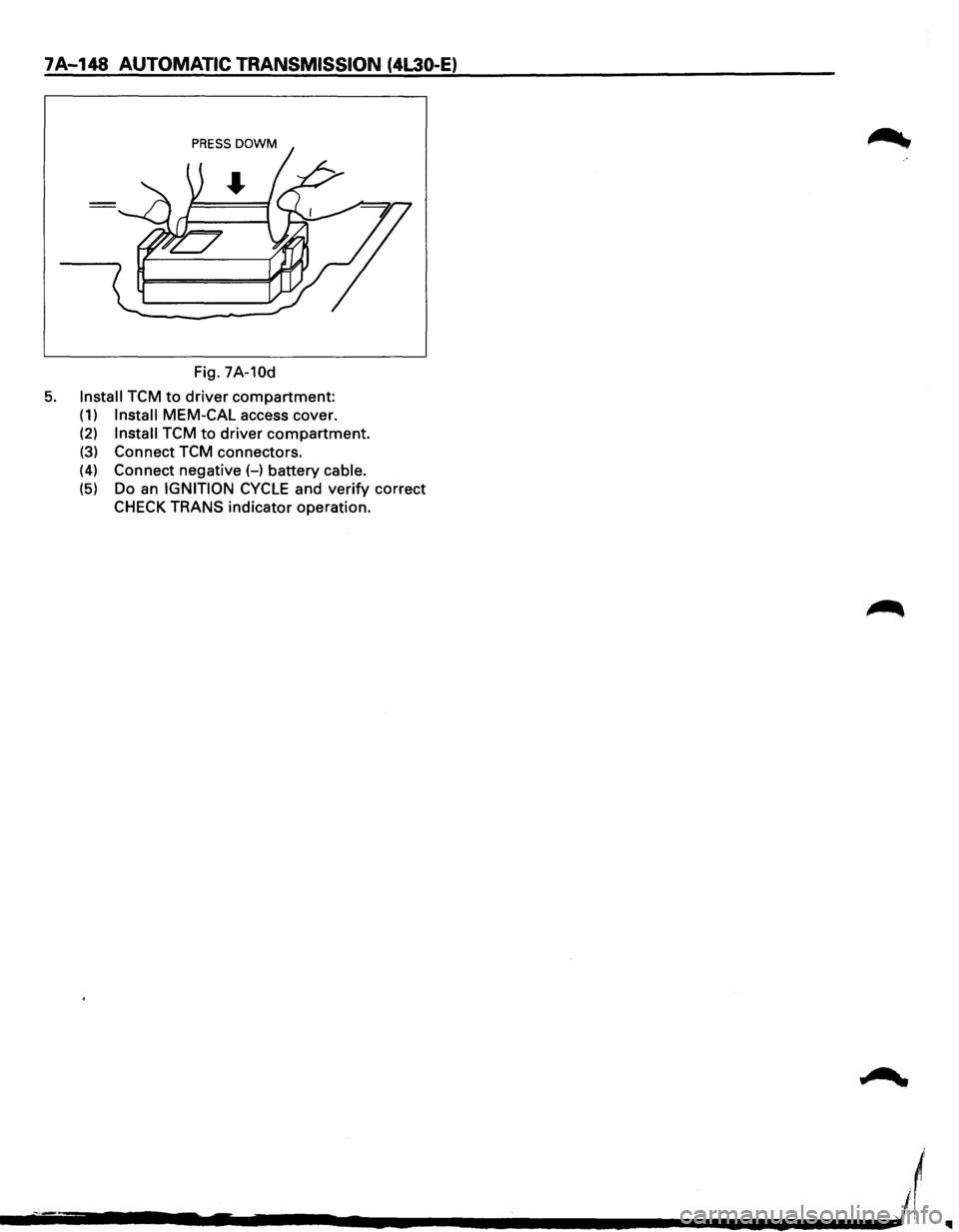
7A-148 AUTOMATIC TRANSMISSION (4L30-E)
Fig. 7A-10d
5. Install TCM to driver compartment:
(1) Install MEM-CAL access cover.
(2) Install TCM to driver compartment.
(3) Connect TCM connectors.
(4) Connect negative(-) battery cable.
(5) Do an IGNITION CYCLE and verify correct
CHECK TRANS indicator operation.
l
--------~.-------~------------~~--~'1
Page 1024 of 1928
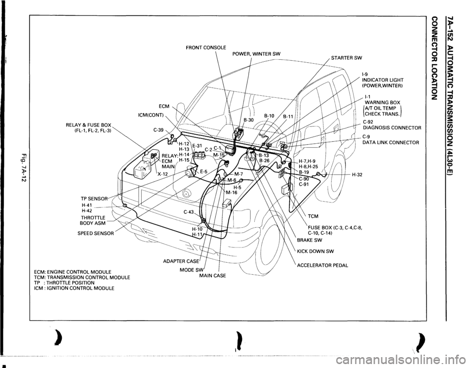
•
, cCi" -.J )> I .... N
RELAY
& FUSE BOX
(FL-1, FL-2, FL-3)
THROTTLE BODYASM SPEED SENSOR
ECM:
ENGINE CONTROL
MODULE
TCM:
TRANSMISSION CONTROL
MODULE
TP :THROTTLE
POSITION
ICM
: IGNITION CONTROL
MODULE
)
ECM
ICM(CONT) FRONT
CONSOLE
MODESW
MAIN
CASE
,}
~H-32
FUSE BOX
(C-3,
C-4,C-8,
C-10,
C-14)
BRAKE
SW
KICK DOWN
SW
ACCELERATOR PEDAL
1-9 INDICATOR LIGHT
(POWER, WINTER) 1-1 WARNING BOX (AfT
OIL
TEMP )
CHECK TRANS.
C-92 DIAGNOSIS CONNECTOR C-9 DATA
LINK CONNECTOR
}
(') 0 2
2 m a ::IJ r-0 (') !4 0 2
" t .... C1l N l> c: a s: !4 n -4 ::IJ l> 2 rA s: c;; rA 0 2 ~ ~ 0 I m
Page 1199 of 1928
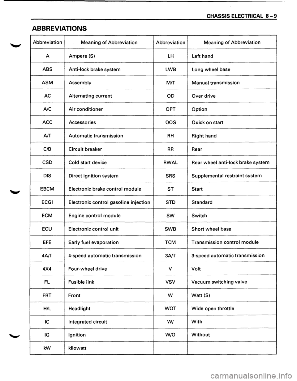
CHASSIS ELECTRICAL 8-9
ABBREVIATIONS
Abbreviation
Meaning of Abbreviation Abbreviation Meaning of Abbreviation
A Ampere
(S) LH Left
hand
ABS Anti-lock brake system LWB Long wheel base
ASM Assembly M!f Manual transmission
AC Alternating current OD Over drive
A/C
Air conditioner OPT Option
ACC Accessories QOS Quick on start
A/T Automatic
transmission
RH Right hand
C/8 Circuit
breaker
RR Rear
CSD Cold start device RWAL Rear
wheel anti-lock brake system
DIS Direct ignition system SRS Supplemental restraint system
EBCM Electronic brake control module
ST Start
ECGI Electronic control gasoline injection STD Standard
ECM Engine control module sw Switch
ECU Electronic control unit SWB Short wheel
base
EFE Early fuel evaporation TCM Transmission
control module
4A/T 4-speed
automatic transmission
3A/T 3-speed
automatic transmission
4X4 Four-wheel drive
v Volt
FL Fusible link vsv Vacuum switching valve
FRT Front w Watt {S)
H/L Headlight WOT Wide open throttle
IC Integrated circuit WI With
IG Ignition W/0 Without
kW
kilowatt
Page 1214 of 1928
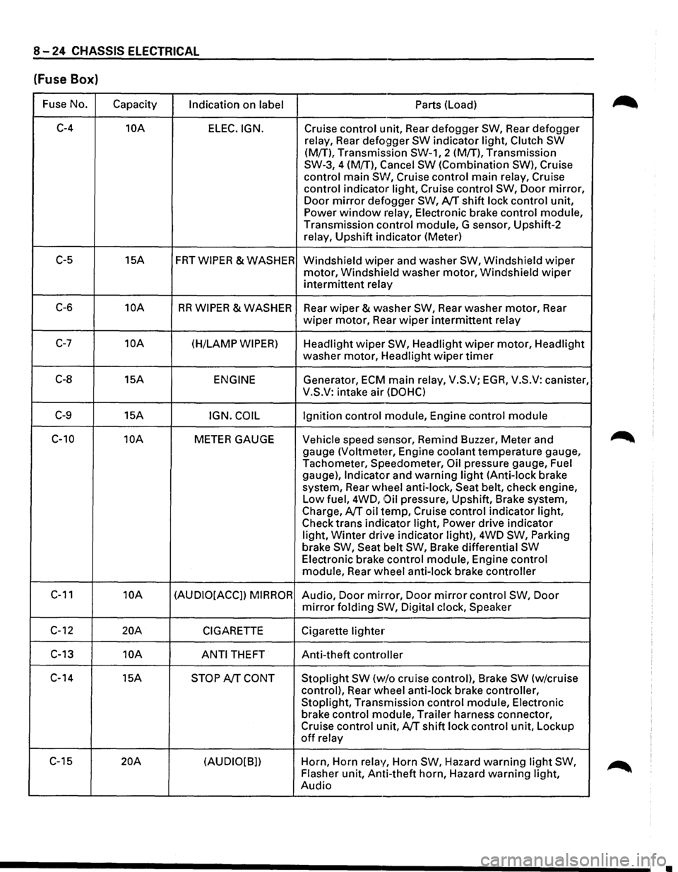
8-24 CHASSIS ELECTRICAL
(Fuse Box)
Fuse No.
Capacity Indication on label Parts (Load)
C-4 10A
ELEC.IGN. Cruise control unit, Rear defogger SW, Rear defogger
relay, Rear
defo9ger SW indicator light, Clutch SW
(M{T), Transmission SW-1, 2 (M!T), Transmission
SW-3, 4 (M{T), Cancel
SW (Combination SW), Cruise
control main
SW, Cruise control main relay, Cruise
control indicator light, Cruise control
SW, Door mirror,
Door mirror defogger SW, AfT shift lock control unit,
Power window relay, Electronic brake control module,
Transmission control module, G sensor, Upshift-2
relay, Upshift indicator (Meter)
C-5 15A FRTWIPER &WASHER
Windshield wipt~r and washer SW, Windshield wiper
motor, Windshit~ld washer motor, Windshield wiper
intermittent relay
C-6 10A RR WIPER & WASHER
Rear wiper & washer SW, Rear washer motor, Rear
wiper motor, Rear wiper intermittent relay
C-7 10A (H/LAMP WIPER) Headlight wiper SW, Headlight wiper motor, Headlight
washer motor, Headlight
wiper timer
C-8 15A ENGINE Generator, ECM main relay, V.S.V; EGA, V.S.V: canister,
V.S.V: intake air
(DOHC)
C-9 15A IGN. COIL Ignition control module, Engine control module
C-10 10A METER GAUGE Vehicle speed stmsor, Remind Buzzer, Meter and
gauge
(Voltmeter, Engine coolant temperature gauge,
Tachometer, Speedometer,
Oil pressure gauge, Fuel
gauge),
Indicator and warning light (Anti-lock brake
system, Rear wheel anti-lock, Seat belt, check engine,
Low fuel, 4WD,
Oil pressure, Upshift, Brake system,
Charge,
AfT oil temp, Cruise control indicator light,
Check trans indicator light,
Power drive indicator
light,
Winter drive indicator light), 4WD SW, Parking
brake SW, Seat belt SW, Brake differential SW
Electronic brake control module, Engine control
module, Rear wheel anti-lock brake controller
C-11 10A (AUDIO[ACCJ) MIRROR Audio, Door mirror, Door mirror control SW, Door
mirror folding SW, Digital clock, Speaker
C-12 20A CIGARETTE Cigarette lighter
C-13 10A
ANTI THEFT Anti-theft controller
C-14 15A
STOP AfT CONT Stoplight SW (w/o cruise control), Brake SW (w/cruise
control), Rear wheel anti-lock brake controller,
Stoplight, Transmission control module, Electronic
brake control module, Trailer harness connector,
Cruise control unit,
AfT shift lock control unit, Lockup
off relay
C-15
20A (AUDIO[B]) Horn,
Horn relay, Horn SW, Hazard warning light SW,
Flasher unit, Anti-theft horn, Hazard warning light,
Audio
•
Page 1220 of 1928
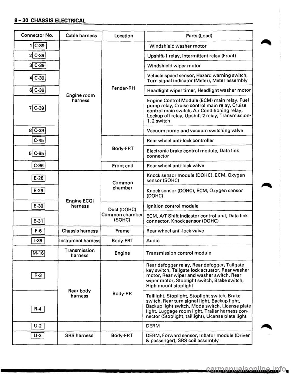
8-30 CHASSIS ELECTRICAL
Connector No.
Cable harness
Location Parts (load)
1jC-39I Windshield washer motor
21 C-391 Upshift-1 relay, Intermittent relay (Front)
31 C-391 Windshield wiper motor
41 C-39j Vehicle speed
sensor, Hazard warning switch,
Turn
signal indicator (Meter), Meter assembly
sl C-391 Fender-RH Headlight wiper timer, Headlight washer motor
Engine room
harness Engine Control Module (ECM)
main relay, Fuel
71 C-391 pump relay, Cruise control main relay, Cruise
control main switch, Air Conditioning relay,
Lockup off relay, Upshift-2 relay, Transmission-
1, 2 switch
al C-391 Vacuum pump and vacuum switching valve
I C-451 Rear wheel anti-lock controller
sl c-asl
Body-FRT Electronic brake control module, Data link
connector
I C-961 Front end Rear wheel
anti-lock valve
I E-281 Knock sEmsor module (DOHC), ECM, Oxygen
Common sensor (SOHC)
I E-291 chamber Knock sensor (DOHC), ECM, Oxygen sensor
(DOHC)
Engine
ECGI
I E-30 I harness Duct (DOHC) Ignition control
module
Common chamber
ECM, AfT Shift indicator control unit, Data link
I
E-311 (SOHC) connector, Knock sensor (DOHC)
~ Chassis harness Frame
Rear wheel anti-lock valve
11-391 Instrument
harness
Body-FRT Audio
IM-161 Transmission
Engine Transmission control module harness
Rear defogger
relay, Rear defogger, Tailgate
~
key switch, Tailgate lock actuator, Rear washer
motor, A:ear wiper and washer switch, Rear
wiper motor, Stoplight switch, Brake switch,
High
mount stoplight
Rear body Body-RR
harness Taillight, Stoplight, Stoplight switch, Brake
switch,
near turn signal light, Backup light,
~
Backup light switch, Mode switch, License plate
light, Lu!;)gage room light, Trailer harness con-
nector
(Stoplight, taillight), License plate light
~ DERM
00 SRS harness Body-FRT
DERM, Forward sensor, Inflator module (Driver
& passenger),
SRS coil assembly
•
Page 1237 of 1928
CHASSIS ELECTRICAL 8-47
ENGINE CONTROL MODULE (ECM)
GENERAL DESCRIPTION
The ECM is used to control the fuel system of the
vehicle, especially in controlling the following items.
1. FUEL CONTROL
The amount of fuel and air sent into the combus
tion chamber is controlled by controlling the fuel
sent through the injector.
2. ELECTRIC FUEL PUMP (INSTALLED IN
THE FUEL TANK)
The in-tank fuel pump is controlled by the ECM.
When starter switch is turned on, the pump will
run for 2 seconds, then stop unless the engine is
cranking
or running.
3. IGNITION CONTROL
The system is controlled by the spark timing con
trol function of the ECM.
4. CIRCULATION OF EXHAUST GAS
The system controls the formation of NOx by
returning a small amount of exhaust gas to the
intake manifold
through the control valve.
'-" lAC: Idle air control
5. CONTROL OF AIR CONDITIONING (A/C)
For improved engine idling performance, the sys
tem controls the operation of the air conditioner
by regulating the
clutch operation ofthe A/C com
pressor in accordance
with changes in operation.
6. IDLE AIR CONTROL
The system controls the lAC Valve for the desired
idle speed in accordance
with changes in
operation.
7. DIAGNOSIS OF TROUBLES
When a sensor detects any signal that the ECM is
in
an abnormal condition, the ECM turns on the
malfunction
indicator (CHECK ENGINE) light in
the meter, and stores at the same
time the corre
sponding diagnostic
trouble code (DTC) in the
memory to indicate to which system or circuit the
trouble represented by the
DTC belongs.
The ECM inspection connector (data link connec
tor) is used
to retrieve the DTCs stored from the
ECM.
Refer to Section 6 "ENGINE DIAGNOSIS" for de
tails.
Page 1238 of 1928
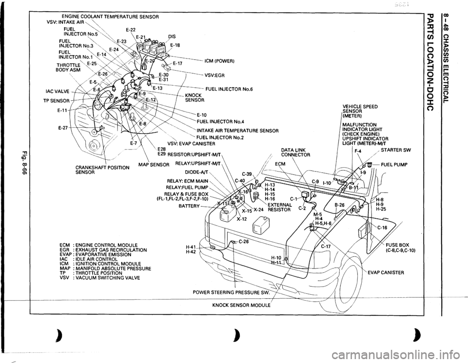
.~·-
, ca· CIO I O'l O'l
ENGINE
COOLANT TEMPERATURE SENSOR
VSV:
INTAKE
AIR~""-"-,
FUEL
~,
'"-
E-22
INJECTOR
No.5
'~~
FUEL
~
"':·.E-23
INJECTOR
No.3
"-
'"<
FUEL
"-
·,,,
E-~
4 /'
INJECTOR
No.'1'~-
1~4 "...
.......
. .......
' '
/
BODY
ASM
"-..'-
>
DIS / / E-18
ICM !POWER)
THROTILE '
E-~5·.-..,
.. '-, ·,/
r
E-2~,,
/E-5v~~;>o~~
--vsv:EGR
FUEL
INJECTOR
No.6
E-11
~E-10 ~FUEL
INJECTOR
No.4
E-27-+
"'
:1
~
.........
_
'-......
"·INTAKE
AIR TEMPERATURE SENSOR
ECM EGR EVAP
lAC
ICM MAP TP vsv )
X
·"
~
FUEL
INJECTOR
No.2
VSV: EVAP CANISTER
E28
E29
RESISTOR:UPSHIFT-M/T
CRANKSHAFT
POSITION
SENSOR
MAP
SENSOR RELAY:UPSHIFT-M/T ,
ENGINE
CONTROL
MODULE
EXHAUST GAS RECIRCULATION
EVAPORATIVE EMISSION IDLE
AIR CONTROL
IGNITION CONTROL
MODULE
MANIFOLD ABSOLUTE PRESSURE
THROTILE POSITION VACUUM
SWITCHING
VALVE
DIODE-AfT
'...,
RELAY:
ECM
MAIN
~"'-.,'...,
RELAY:FUEL
PUMP
'....
'
RELAY
& FUSE BOX
(FL-1,FL-2,FL-3,F-2,F-10)
BATIERY~
H-41 H-42~
KNOCK SENSOR
MODULE
)
DATA
LINK
CONNECTOR
VEHICLE
SPEED
SENSOR
(METER)
MALFUNCTION INDICATOR LIGHT (CHECK ENGINE) UPSHIFT INDICATOR LIGHT
(METER)-M/T
STARTER
SW
·~FUEL
PUMP
EVAP CANISTER
)
~
co I
~
~ co
(/)
0
r-
:::t
0
)> C/)
0
C/)
~
Cii
-
m
0
r-m
2
0
I
~
c
:a
0
0 )>
J:
r-
0