ignition ISUZU TROOPER 1995 Workshop Manual
[x] Cancel search | Manufacturer: ISUZU, Model Year: 1995, Model line: TROOPER, Model: ISUZU TROOPER 1995Pages: 1928
Page 981 of 1928
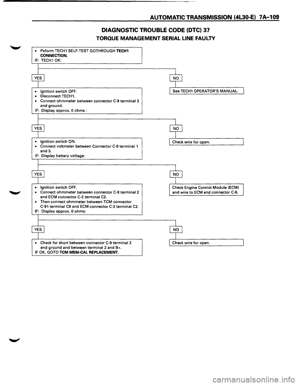
AUTOMATIC TRANSMISSION (4L30-E) 7A-109
DIAGNOSTIC
TROUBLE CODE (DTC) 37
TORQUE MANAGEMENT SERIAL LINE FAULTY
• Peform TECH1 SELF-TEST GOTHROUGH TECH1 CONNECTION. IF: TECH1 OK:
• Ignition switch OFF. • Disconnect TECH1.
• Connect ohmmeter between connector C-9 terminal 3
and ground.
IF: Display approx. 0 ohms :
• Ignition switch ON.
• Connect voltmeter between Connector C-9 terminal 1
and 3.
IF: Display battery voltage:
• Ignition switch OFF. • Connect ohmmeter between connector C-9 terminal2 and ECM connector C-2 terminal C2. • Then connect ohmmeter between TCM connector C-91 terminal CB and ECM connector C-2 terminal C2. IF: Display approx. 0 ohms:
• Check for short between connector C-9 terminal 2
and ground and between terminal 2 and B+. IF OK, GOTO TCM MEM·CAL REPLACEMENT.
See TECH1 OPERATOR'S MANUAL
Check wire for open.
Check Engine Control
Module (ECM)
and wire
to ECM and connector C-9.
Page 982 of 1928
7A-110 AUTOMATIC TRANSMISSION (4L30-E)
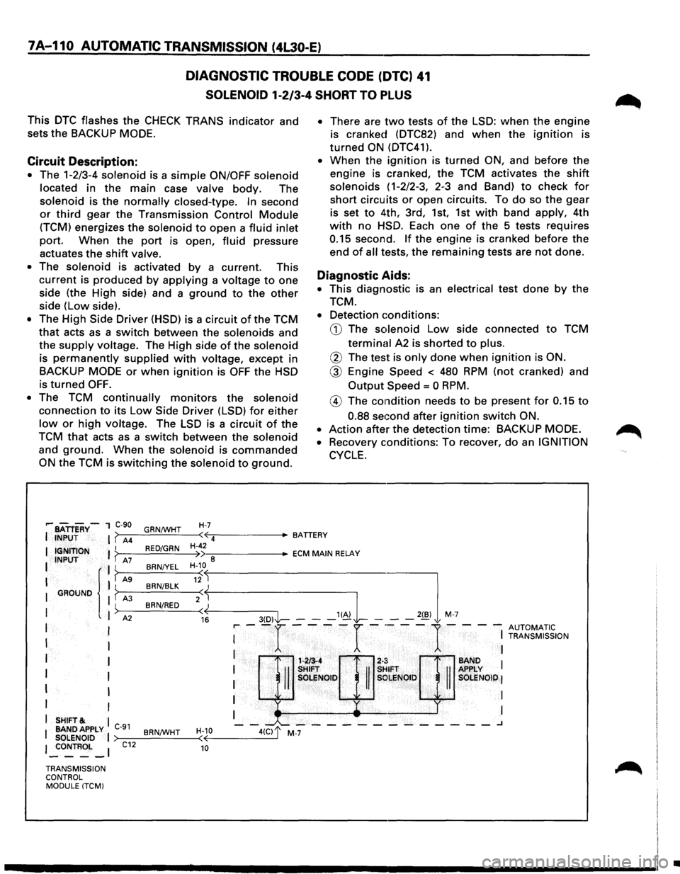
DIAGNOSTIC TROUBLE CODE (DTC) 41
SOLENOID 1-2/3-4 SHORT TO PLUS
This DTC flashes the CHECK TRANS indicator and
sets
the BACKUP MODE.
Circuit Description:
• The 1-2/3-4 solenoid is a simple ON/OFF solenoid
located in the main case valve body. The
solenoid is the normally closed-type. In second
or third gear the Transmission Control Module
(TCM) energizes the solenoid to open a fluid inlet
port. When the port is open, fluid pressure
actuates
the shift valve.
• The solenoid is activated by a current. This
current is produced by applying a voltage to one
side (the High side) and a ground to the other
side (Low side).
• The High Side Driver (HSD) is a circuit of the TCM
that acts as a switch between the solenoids and
the supply voltage. The High side of the solenoid
is permanently supplied with voltage, except in
BACKUP MODE or when ignition is OFF the HSD
is
turned OFF.
•
The TCM continually monitors the solenoid
connection to its Low Side Driver (LSD) for either
low or high voltage. The LSD is a circuit of the
TCM that acts as a switch between the solenoid
and ground. When the solenoid is commanded
ON the TCM is switching the solenoid to ground.
H-7
• There are two tests of the LSD: when the engine
is cranked (DTC82) and when the ignition is
turned ON (DTC41 ).
• When the ignition is turned ON, and before the
engine is cranked, the TCM activates the shift
solenoids ( 1-2/2-3, 2-3 and Band) to check for
short circuits or open circuits. To do so the gear
is set to 4th, 3rd, 1st, 1st with band apply, 4th
with no HSD. Each one of the 5 tests requires
0.15 second. If the engine is cranked before the
end of all tests, the remaining tests are not done.
Diagnostic Aids:
• This diagnostic is an electrical test done by the
TCM.
• Detection conditions:
CD The solenoid Low side connected to TCM
terminal A2 is shorted to plus.
@ The test is only done when ignition is ON.
@ Engine Speed < 480 RPM (not cranked) and
Output Speed = 0 RPM.
@ The condition needs to be present for 0.15 to
0.88 seGond after ignition switch ON.
•
Action after the detection time: BACKUP MODE.
•
Recovery conditions: To recover, do an IGNITION
CYCLE.
,.... BATTERY-1 C-90
I INPUT I ( A4 GRN/WHT
I { I r"'
( 12 BRN/BLK I I GROUND I f A3 BRN/RED 2(~
I
I A2 ( 16 I I
I I
I
I
I I
I I
I I
I
SHIFT& I
I BANDAPPLY C-91 BRN/WHT H-10
SOLENOID I (
I _:oNTROL _I C12 10
·~ ciJr
SHifT . SHIFT
II II SOLENOID II SOLENOID
' y
-"--------------.J
•-::------ECM MAIN RELAY
>---=---=--~--< ~----3(-D-,1'1-- --"~ L -2(B,l M 7
r-- -r ----r -·---
1-- --
AUTOMATIC I
I TRANSMISSION
I I
I BAND 1 APPLY I SOLENOID I
I I
I I
TRANSMISSION
CONTROL MODULE (TCMI
•
Page 983 of 1928
AUTOMATIC TRANSMISSION (4L30-E) 1 A-111
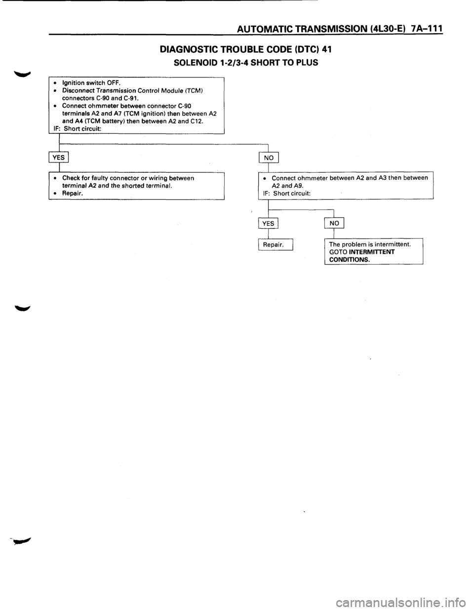
DIAGNOSTIC TROUBLE CODE (DTC) 41
SOLENOID 1·2/3-4 SHORT TO PLUS
• Ignition switch OFF.
• Disconnect Transmission Control Module (TCM)
connectors C-90 and C-91.
• Connect ohmmeter between connector C-90 terminals A2 and A7 (TCM ignition) then between A2 and A4 (TCM battery) then between A2 and C12.
IF: Short circuit:
• Check for faulty connector or wiring between terminal A2 and the shorted terminal.
• Repair.
• Connect ohmmeter between A2 and A3 then between
A2 and A9.
IF: Short circuit:
The
problem is intermittent. GOTO INTERMITTENT
CONDITIONS.
Page 984 of 1928
7A-112 AUTOMATIC TRANSMISSION (4l30-E)
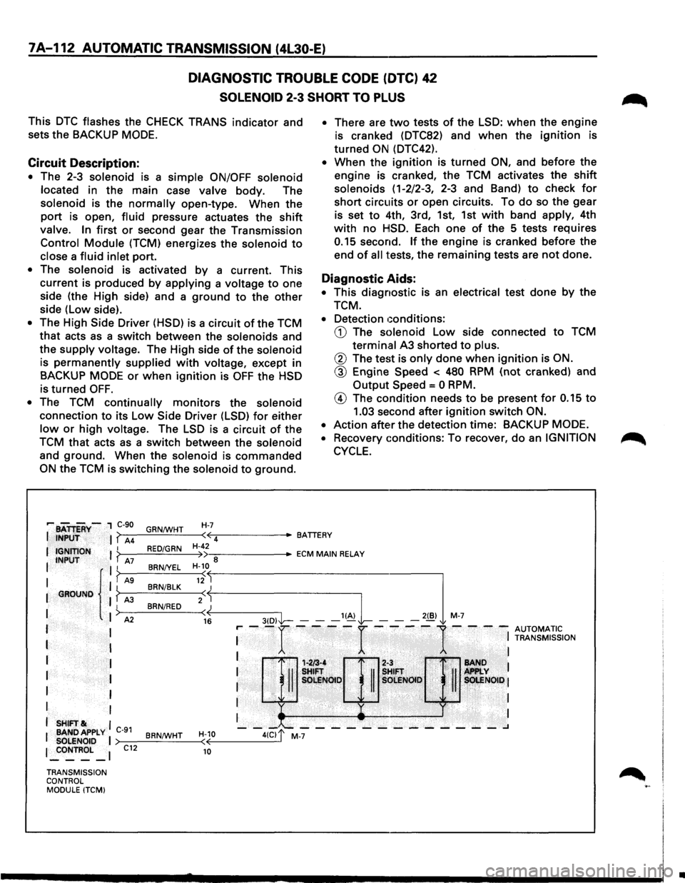
DIAGNOSTIC TROUBLE CODE (DTC) 42
SOLENOID 2-3 SHORT TO PLUS
This DTC flashes the CHECK TRANS indicator and
sets the BACKUP MODE.
Circuit Description:
• The 2-3 solenoid is a simple ON/OFF solenoid
located
in the main case valve body. The
solenoid is the normally open-type. When the
port is open, fluid pressure actuates the shift
valve. In first or second gear the Transmission
Control Module (TCM) energizes the solenoid to
close a fluid inlet port.
• The solenoid is activated by a current. This
current is produced
by applying a voltage to one
side (the High side) and a
ground to the other
side (Low side).
• The High Side Driver (HSD) is a circuit of the TCM
that acts as a switch between the solenoids and
the
supply voltage. The High side of the solenoid
is permanently supplied with voltage, except in
BACKUP
MODE or when ignition is OFF the HSD
is turned OFF.
• The TCM continually monitors the solenoid
connection to its Low Side Driver (LSD) for either
low or high voltage. The LSD is a circuit of the
TCM
that acts as a switch between the solenoid
and ground. When the solenoid is commanded
ON the TCM is switching the solenoid to ground.
• There are two tests of the LSD: when the engine
is cranked (DTC82) and
when the ignition is
turned ON (DTC42).
• When the ignition is turned ON, and before the
engine is cranked, the TCM activates the
shift
solenoids (1-2/2-3, 2-3 and Band) to check for
short circuits or open circuits. To do so the gear
is set
to 4th, 3rd, 1st, 1st with band apply, 4th
with no HISD. Each one of the 5 tests requires
0.15 second. If the engine is cranked before the
end
of all tests, the remaining tests are not done.
Diagnostic Aids:
• This diagnostic is an electrical test done by the
TCM.
• Detection ~:onditions:
CD The solenoid Low side connected to TCM
terminal A3 shorted to plus.
® The test is only done when ignition is ON.
® Engine Speed < 480 RPM (not cranked) and
Output Speed = 0 RPM.
@ The condition needs to be present for 0.15 to
1.03 second after ignition switch ON.
•
Action after the detection time: BACKUP MODE.
• Recovery conditions: To recover, do an IGNITION
CYCLE.
•
Page 985 of 1928
AUTOMATIC TRANSMISSION (4L30-E) 7A-113
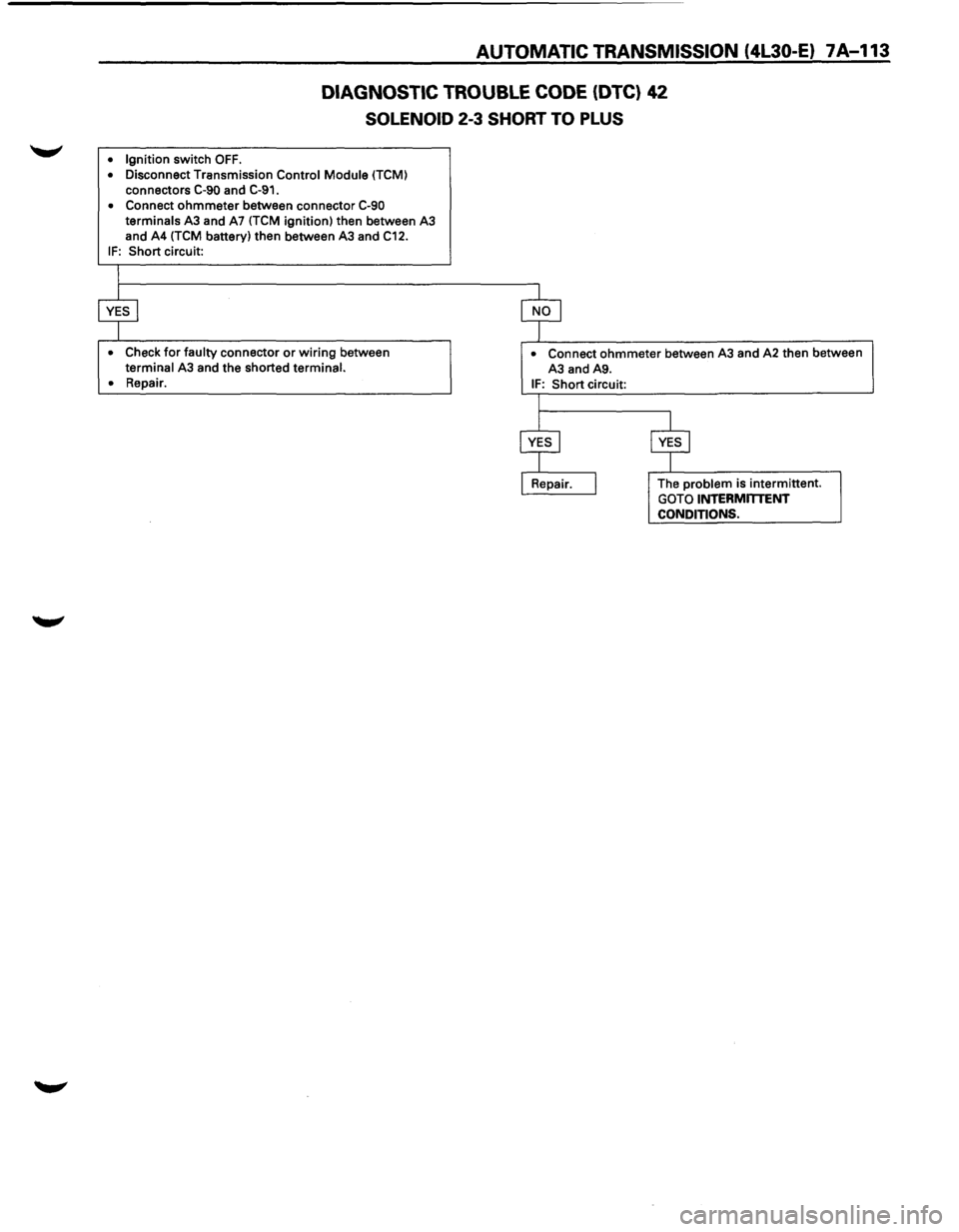
DIAGNOSTIC TROUBLE CODE (DTC) 42
SOLENOID 2-3 SHORT TO PLUS
• Ignition switch OFF.
• Disconnect Transmission Control Module (TCM)
connectors C-90 and C-91.
• Connect ohmmeter between connector C-90 terminals A3 and A7 (TCM ignition) then between A3
and A4 (TCM battery) then between A3 and C12.
IF: Short circuit:
• Check for faulty connector or wiring between terminal A3 and the shorted terminal.
•
Repair.
• Connect ohmmeter between A3 and A2 then between
A3 and A9.
IF: Short circuit:
The
problem is intermittent. GOTO INTERMmENT CONDITIONS.
Page 986 of 1928
7A-114 AUTOMATIC TRANSMISSION (4l30-E)
DIAGNOSTIC TROUBLE CODE (DTC) 43
TCC HIGH SHORT TO GROUND
This DTC does NOT flash the CHECK TRANS
indicator and does NOT set the BACKUP MODE.
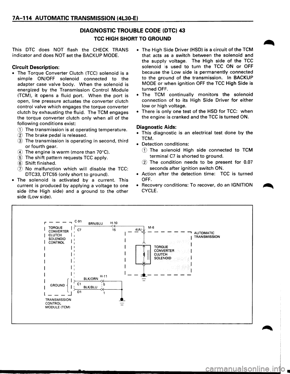
Circuit Description:
• The Torque Converter Clutch (TCC) solenoid is a
simple ON/OFF solenoid connected to the
adapter case
valve body. When the solenoid is
energized
by the Transmission Control Module
(TCM), it opens a fluid port. When the port is
open,
line pressure actuates the converter clutch
control valve
which engages the torque converter
clutch by exhausting the fluid. The TCM engages
the
torque converter clutch only when all of the
following conditions exist:
G) The transmission is at operating temperature.
@ The brake pedal is released.
® The transmission is operating in second, third
or fourth gear.
® The engine is warm (more than 70°C).
@ The shift pattern requests TCC apply.
® Shift finished.
(f) No malfunction which will disable the TCC:
DTC33, DTC55 (only short to ground).
• The solenoid is activated by a current. This
current is produced
by applying a voltage to one
side (the High side) and a
ground to the other
side (low side).
• The High Side Driver (HSD) is a circuit of the TCM
that acts as a switch between the solenoid and
the supply voltage. The High side of the TCC
solenoid is used to turn the TCC ON or OFF
because the Low side is permanently connected
to the ground of the transmission. In BACKUP
MODE or when ignition OFF the TCC High Side is
turned OFIF.
• The TCM continually monitors the solenoid
connection of to its High Side Driver for either
low or high voltage.
• There is only one test of the HSD for TCC: when
the engine is cranked and the TCC is turned ON.
Diagnostic .Aids:
• This diagnostic is an electrical test done by the
TCM.
• Detection conditions:
G) The solenoid High side connected to TCM
terminal C7 is shorted to ground.
@ The condition needs to be present for 0.07
seconds after ignition switch ON.
•
Action after the detection time: TCC is turned
OFF.
• Recovery eonditions: To recover, do an IGNITION
CYCLE.
r - - --, C-S1 BRN/BLU H-10 TORQUE I >-----__:_---<1 ~ ~'---------4-(A~) \1, M-6
g~~i~~TER I C7 II --1-- -- ---, AUTOMATIC
SOLENOID 1 TRANSMISSION
I
I
CONTROL
I I
I {I? GROUND I I C1 )
l---~ 01
TRANSMISSION CONTROL
MODULE (TCM)
I
: II
I
TORQUE CONVE:RTER CLUTCH
SOLEt\A0
I I H-11 - -~· - - - - - - -BLKJORN ~
9
-=-,5 BLK/BLU (
1
•
Page 987 of 1928
AUTOMATIC TRANSMISSION (4L30•E) 7A-115
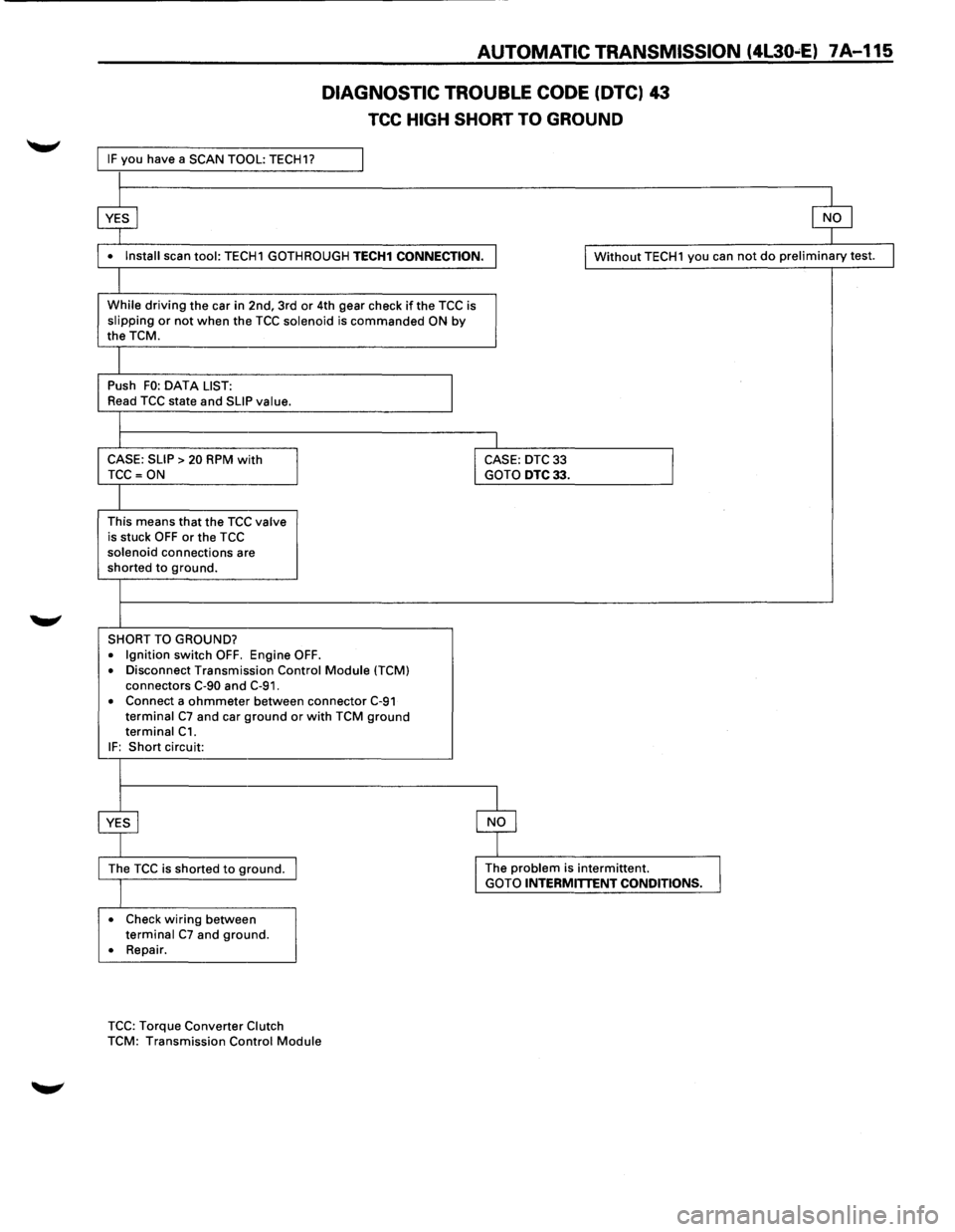
IF you have a SCAN TOOL: TECH1?
$
DIAGNOSTIC TROUBLE CODE (OTC) 43
TCC HIGH SHORT TO GROUND
$
• Install scan tool: TECH1 GOTHROUGH TECH1 CONNECTION . I Without TECH1 you can not do preliminary test.
While driving the car in 2nd, 3rd or 4th gear check if the TCC is slipping or not when the TCC solenoid is commanded ON by the TCM.
Push FO: DATA LIST:
I Read TCC state and SLIP value.
CASE: SLIP
> 20 RPM with I CASE: DTC 33
I TCC =ON GOTO DTC33.
This means that the TCC valve is stuck OFF or the TCC solenoid connections are shorted to ground.
SHORT TO GROUND?
• Ignition switch OFF. Engine OFF .
• Disconnect Transmission Control Module ITCM) connectors C-90 and C-91.
• Connect a ohmmeter between connector C-91 terminal C7 and car ground or with TCM ground terminal C1.
IF: Short circuit:
~ $
The TCC is shorted to ground. I The problem is intermittent.
I GOTO INTERMITTENT CONDITIONS.
• Check wiring between terminal C7 and ground.
• Repair .
TCC: Torque Converter Clutch
TCM: Transmission Control Module
I
Page 988 of 1928
7A-116 AUTOMATIC TRANSMISSION (4L30-E)
DIAGNOSTIC TROUBLE CODE (DTC) 44
BAND APPLY SOLENOID SHORT TO PLUS
This DTC flashes the CHECK TRANS indicator and
sets the BACKUP
MODE.
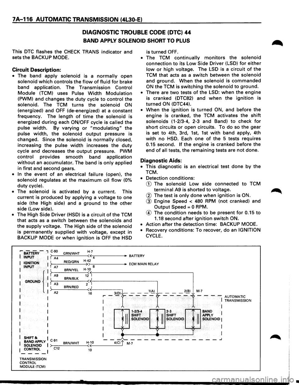
Circuit Description:
• The band apply solenoid is a normally open
solenoid which controls the flow of fluid for brake
band
application. The Transmission Control
Module (TCM) uses Pulse Width Modulation
(PWM) and changes the duty cycle to control the
solenoid. The TCM turns the solenoid ON
(energized) and OFF (de-energized) at a constant
frequency. The
length of time the solenoid is
energized
during each ON/OFF cycle is called the
pulse width. By varying or "modulating" the
pulse width, the solenoid output pressure is
changed.
Since the solenoid is normally closed,
increasing the pulse width increases the duty
cycle and decreases the output pressure. PWM
control provides smooth band application
without an accumulator. The band is only applied
in first and second gears.
• In the event of an electrical failure (open), the
solenoid regulates at the maximum oil flow (0%
duty cycle).
•
The solenoid is activated by a current. This
current is produced by
applying a voltage to one
side (the High side) and a
ground to the other
side (low side).
• The High Side Driver (HSD) is a circuit of the TCM
that acts as a switch between the solenoids and
the
supply voltage. The High side of the solenoid
is permanently supplied with voltage, except in
BACKUP
MODE or when ignition is OFF the HSD
H-7
is turned OFF.
• The TCM continually monitors the solenoid
connection to its Low Side Driver (LSD) for either
low or high voltage. The LSD is a circuit of the
TCM
that acts as a switch between the solenoid
and ground. When the solenoid is commanded
ON the TCM is switching the solenoid to ground.
• There are two tests of the LSD: when the engine
is cranked (DTC82) and
when the ignition is
turned
ON (DTC44).
• When the ignition is turned ON, and before the
engine is cranked, the TCM activates the
shift
solenoids (1-2/3-4, 2-3 and Band) to check for
short circuits or open circuits. To do so the gear
is set
to 4th, 3rd, 1st, 1st with band apply, 4th
with no HSD. Each one of the 5 tests requires
0.15 second. If the engine is cranked before the
end
of all tests, the remaining tests are not done.
Diagnostic Aids:
• This diagnostic is an electrical test done by the
TCM.
• Detection conditions:
CD The solenoid Low side connected to TCM
termin.al A9 is shorted to voltage.
@ The test is only done when ignition is ON.
@ Engine Speed < 480 RPM (not cranked) and
Output
Speed = 0 RPM.
@ The condition needs to be present for 0.15 to
1.18 second after ignition switch ON.
•
Action after the detection time: BACKUP MODE.
•
Recovery conditions: To recover, do an IGNITION
CYCLE.
,... BATTERY-, C-90
I INPUT I? A4 GRN/WHT ·~-----BATTERY
( 4
I IGNITION I ? I INPUT A7 II
I { I? AS I GROUND I ? A3
I
)
I A2
I I
I
I
I I
I I
I
I
I I
I SHIFT& I
I BANDAPPLY C-91 SOLENOID I 1 _:oNTROL _ 1
TRANSMISSION
CONTROL MODULE (TCMI
C12
RED/GRN
BRN/YEL
BRN/BLK
BRN/RED
BRN/WHT
H-42 •--::------ECM MAIN RELAY )) 8 H-10
«--------3-(D--,I'l----- --'~L -,,,l M-7
( 12
2:j
16 r-- -r ----r ----
1-- --
AUTOMATIC I
I TRANSMISSION
: H::Q]:;& : I OLE SOlENOID I
I I
I I
1-213-4 2-:
-II
SHIFT
II
s SOLE NOlO s
-"--------_______ .J
H-10 ( 10
•
Page 989 of 1928
AUTOMATIC TRANSMISSION (4L30-E) 7A-117
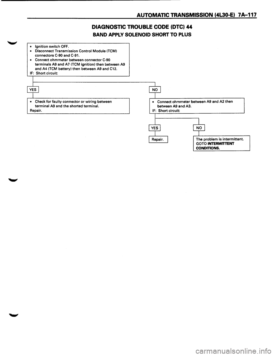
DIAGNOSTIC TROUBLE CODE (DTC) 44
BAND APPLY SOLENOID SHORT TO PLUS
• Ignition switch OFF.
• Disconnect Transmission Control Module (TCM)
connectors C-90 and C-91.
• Connect ohmmeter between connector C-90 terminals A9 and A7 ITCM ignition) then between A9
and A4 (TCM battery) then between A9 and C12. IF: Short circuit:
• Check for faulty connector or wiring between terminal A9 and the shorted terminal. Repair.
• Connect ohmmeter between A9 and A2 then
between A9 and A3.
IF: Short circuit:
The
problem is intermittent.
GOTO INTERMnTENT CONDinONS.
Page 990 of 1928
7A-118 AUTOMATIC TRANSMISSION (4L30-E)
DIAGNOSTIC TROUBLE CODE (DTC) 46
SHIFT HIGH SHORT TO PLUS
This DTC flashes the CHECK TRANS indicator and
sets
the BACKUP MODE.
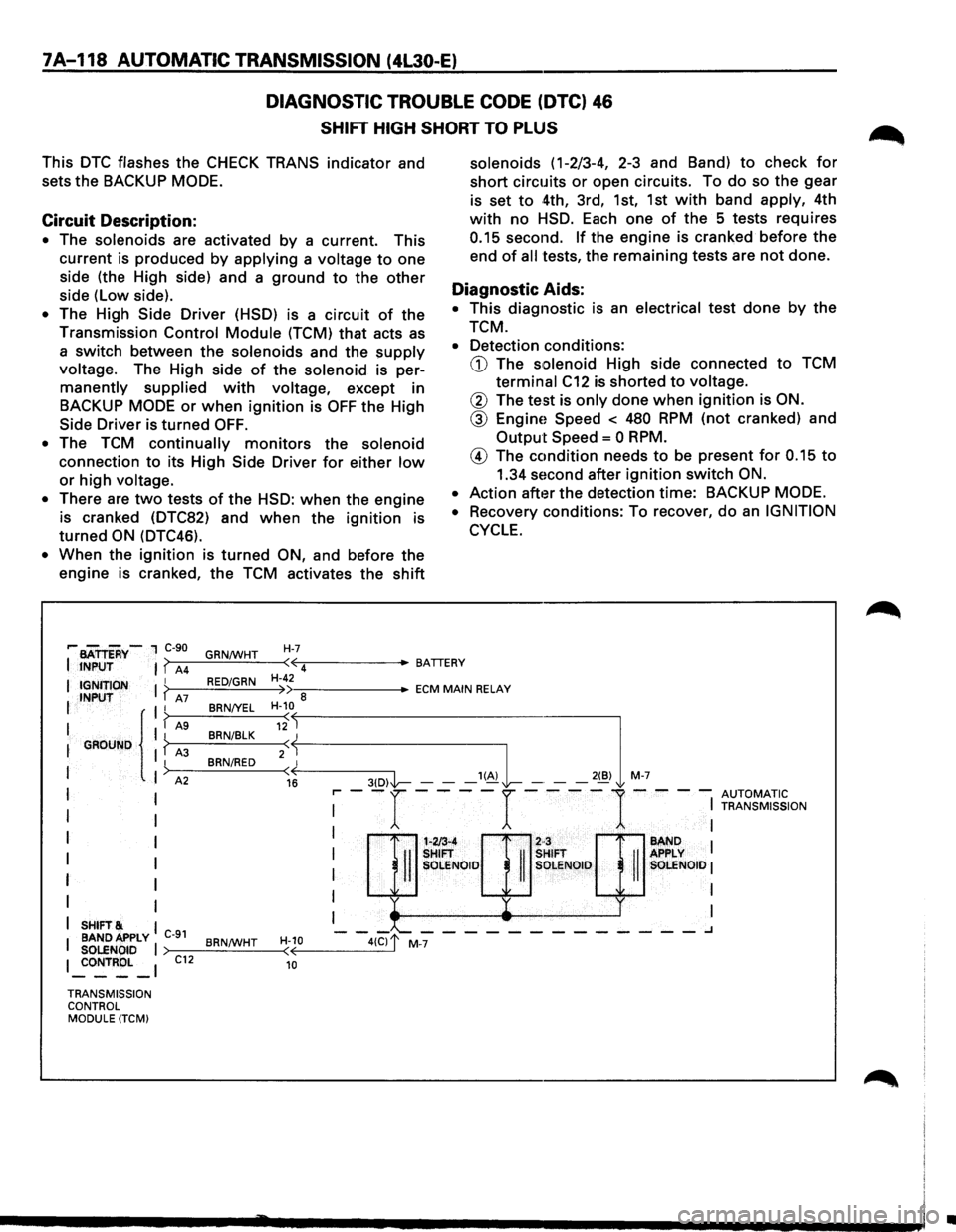
Circuit Description:
• The solenoids are activated by a current. This
current is produced by applying a voltage to one
side (the High side) and a ground to the other
side (Low side).
• The High Side Driver (HSD) is a circuit of the
Transmission Control Module (TCM) that acts as
a
switch between the solenoids and the supply
voltage. The High side of the solenoid is per
manently supplied with voltage, except in
BACKUP
MODE or when ignition is OFF the High
Side
Driver is turned OFF.
•
The TCM continually monitors the solenoid
connection to its High Side Driver for either low
or high voltage.
•
There are two tests of the HSD: when the engine
is cranked (DTC82) and when the ignition is
turned ON (DTC46).
• When the ignition is turned ON, and before the
engine is cranked, the TCM activates the shift
H-7
solenoids (1-2/3-4, 2-3 and Band) to check for
short circuits or open circuits. To do so the gear
is set to 4th, 3rd, 1st, 1st with band apply, 4th
with no HSD. Each one of the 5 tests requires
0.15 second. If the engine is cranked before the
end of all tests, the remaining tests are not done.
Diagnostic Aids:
• This diagnostic is an electrical test done by the
TCM.
•
Detection conditions:
CD The solenoid High side connected to TCM
terminal C12 is shorted to voltage.
@ The test is only done when ignition is ON.
@ EnginE! Speed < 480 RPM (not cranked) and
Output Speed = 0 RPM.
® The condition needs to be present for 0.15 to
1.34 second after ignition switch ON.
•
Action after the detection time: BACKUP MODE.
•
Recovery conditions: To recover, do an IGNITION
CYCLE.
,.. BATTERY-1 C-90
JNPUT ( A4 GRN/WHT
( 4
IGNJTION I RED/GRN H-42
INPUT ( A7 »a BRN/YEL H-10
-:::------ECM MAIN RELAY
G~UND {
I A9 12 I BRN/BLK
2
SHIFT& BAND APPLY C-91 SOLENOID I ~ONTROL _I C12
TRANSMISSION CONTROL MODULE (TCM) BRN/WHT
H-10 ( 10
H/3-4
2·3
II
SHIFT
II
SHIFT
II SOLENOID SOLENOID
:--r----r----1---: ~~~~;ION
BAND I
I APPLY I SOLENOID I
~ I I
I I
-'--------------.J
•