battery replacement ISUZU TROOPER 1995 Owner's Manual
[x] Cancel search | Manufacturer: ISUZU, Model Year: 1995, Model line: TROOPER, Model: ISUZU TROOPER 1995Pages: 1928
Page 1019 of 1928
AUTOMATIC TRANSMISSION (4L30-E) 7A-147
TCM MEM-CAL REPLACEMENT
(TCM: Transmission Control Module)
1. MEM-CAL (Memory and Calibration Unit)
Information for specific transmission and vehicle is
programmed using an integrated circuit called a
MEM-CAL.
This allows one model of controller to be used for
many different vehicles.
The MEM-CAL is located inside the TCM and has
information on the transmission, shift map, etc.
several others.
2. MEM-CAL Replacement
If the diagnostic procedures require MEM-CAL
replacement,
the MEM-CAL should be replaced
using the following procedures.
NOTICE:
The ignition must be "OFF", when disconnecting or
reconnecting the TCM connector, to prevent
internal damage to the TCM.
NOTICE:
To prevent possible Electrostatic Discharge damage
to the TCM, do not touch the connector pins or
soldered components on the circuit board.
MEM-CAL Replacement Procedure:
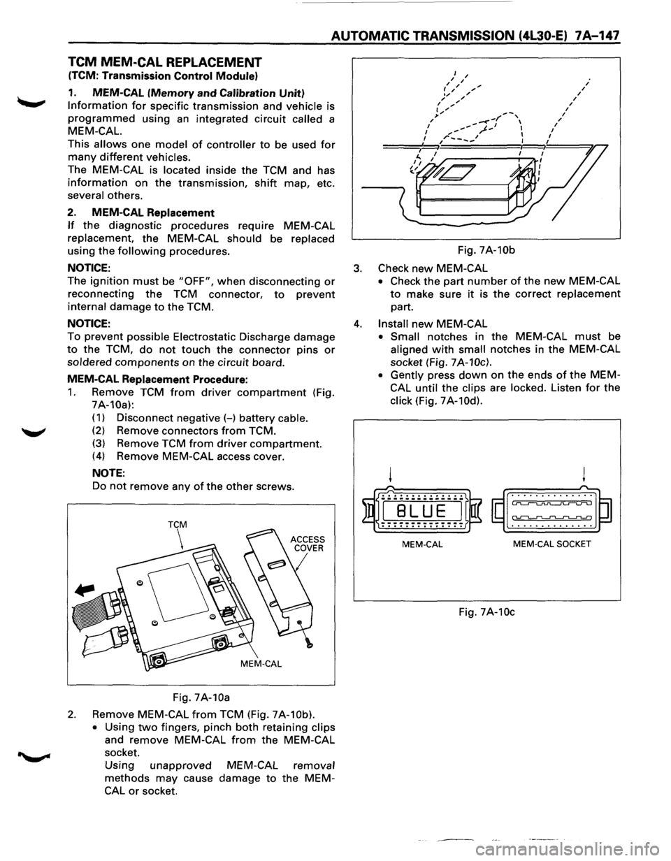
1. Remove TCM from driver compartment (Fig.
7A-10a):
( 1) Disconnect negative (-) battery cable.
(2) Remove connectors from TCM.
(3) Remove TCM from driver compartment.
(4) Remove MEM-CAL access cover.
NOTE:
Do not remove any of the other screws.
Fig.
7A-10a
2. Remove MEM-CAL from TCM (Fig. 7A-10b).
•
Using two fingers, pinch both retaining clips
and remove MEM-CAL from the MEM-CAL
socket.
Using unapproved
methods may cause
CAL or socket.
MEM-CAL removal
damage to the MEM- Fig.
7A-10b
3. Check new MEM-CAL
• Check
the part number of the new MEM-CAL
to make sure it is the correct replacement
part.
4. Install new MEM-CAL
• Small notches in the MEM-CAL must be
aligned with small notches in the MEM-CAL
socket (Fig.
7A-10c).
• Gently
press down on the ends of the MEM
CAL
until the clips are locked. Listen for the
click (Fig. 7A-10d).
! !
($I~rn~ ~~~) . . . . . . . . . . . . . . . ............ .
MEM-CAL MEM-CAL SOCKET
Fig. 7A-10c
Page 1202 of 1928
8-12 CHASSIS ELECTRICAL
FUSIBLE LINK
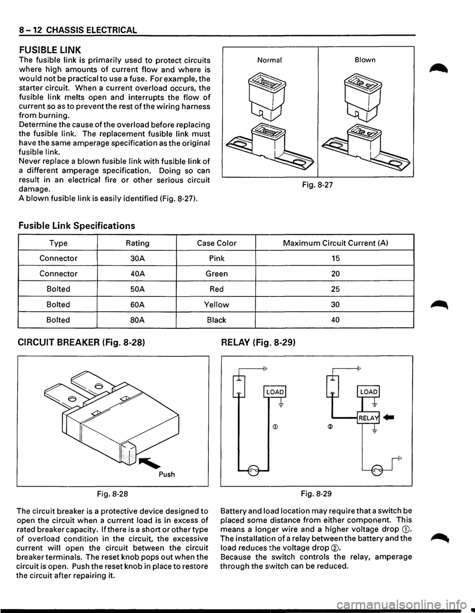
The fusible link is primarily used to protect circuits
where high amounts
of current flow and where is
would not be practical to use a fuse. For example, the
starter circuit. When a current
overload occurs, the
fusible link melts open and interrupts the flow of
current so as to prevent the rest of the wiring harness
from burning.
Determine the cause
ofthe overload before replacing
the fusible link. The replacement fusible link must
have the same amperage specification as the original
fusible link.
Never replace a blown fusible link with fusible link of
a different amperage specification. Doing so can
result in an electrical fire or other serious circuit
damage.
A
blown fusible link is easily identified (Fig. 8-27).
Fusible Link Specifications
Normal Blown
Fig.
8-27
Type Rating
Case Color Maximum Circuit Current (A)
Connector
30A Pink 15
Connector 40A Green 20
Bolted 50 A Red 25
Bolted 60A Yellow 30
Bolted
BOA Black 40
CIRCUIT BREAKER (Fig. 8-28)
Push
Fig. 8-28
The circuit breaker is a protective device designed
to
open the circuit when a current load is in excess of
rated breaker capacity. If there is a short or other type
of overload condition in the circuit, the excessive
current
will open the circuit between the circuit
breaker
terminals. The reset knob pops out when the
circuit is open. Push the reset knob in
place to restore
the circuit after repairing it.
RELAY (Fig. 8-29)
Fig. 8-29
Battery and
load location may require that a switch be
placed some distance from either component. This
means a
longer wire and a higher voltage drop G).
The installation of a relay between the battery and the
load reduces the voltage drop®.
Because the switch controls the relay, amperage
through the switch can be reduced.
..
Page 1637 of 1928
Supplemental Restraint System 9J-13
ON-VEHICLE SERVICE
SERVICE PRECAUTIONS
WARNING: WHEN PERFORMING SERVICE ON OR
AROUND SRS COMPONENTS OR SRS WIRING,
FOLLOW
THE PROCEDURES LISTED BELOW TO
TEMPORARILY DISABLE THE SRS. FAILURE TO
FOLLOW PROCEDURES COULD RESULT IN
POSSIBLE AIR
BAG DEPLOYMENT, PERSONAL
INJURY OR OTHERWISE
UNNEEDED SRS
REPAIRS.
The DERM in Driver-Passenger SRS can maintain
sufficient voltage to cause a deployment for up to 2
minutes after the ignition switch is turned
"OFF," the
battery is disconnected, or the fuse powering the DERM
is removed.
Many of the service procedures require removal of the
"AIR BAG" fuse, and disconnection of the inflator
modules from the deployment loop to avoid an accidental
deployment.
If the inflator module is disconnected from
the deployment loop as noted in the "Disabling the
SRS"
procedure that follows, service can begin immediately
without waiting for the 2-minute time period to expire.
DISABLING THE SRS
REMOVAL
Turn the ignition switch to "OFF"
1. Remove SRS fuse C-21, C-22, C-23 and C-24 from
left dash side lower fuse block.
2. Disconnect yellow 3-way connector at the base of
steering column.
3. Remove 1/P compartment door assembly, Refer to
"Passenger inflator module replacement" in section
9J-132.
4. Disconnect yellow 4-way connector behind the 1/P
compartment door assembly.
IMPORTANT
• With the "AIR BAG" fuse removed and ignition switch
"ON," if Fuse 21 left. the "AIR BAG" warning lamp will
be "ON." This is normal operation and does not
indicate an
SRS malfunction.
ENABLING THE SRS
INSTALLATION
Turn ignition switch to "LOCK" and remove key.
1. Connect yellow 4-way connector for passenger
inflator module.
2. 1/P compartment door assembly, Refer to
"Passenger inflator module replacemenf' in section
9J-3.
3. Connect yellow 2-way connector at the base of the
steering column.
4. Install "AIR BAG" fuse C-21, C-22, C-23 and C-24 to
left dash side lower fuse block.
Turn ignition switch to
"RUN" and verify that the "AIR
BAG"
warning lamp flashes seven times and then turns
"OFP' If it does not operate as described, perform the
"SRS Diagnostic System Check" in section 9J-2.
HANDLING/INSTALLATION/DIAGNOSIS
1. Inflator modules should not be subjected to
temperatures above
65°C{150°F).
2. Discriminating sensors, inflator modules, arming
sensors, or DERMs should not be used if they have
been dropped from a height
of 91.4 centimeters
{3feet).
3. When a discriminating sensor or arming sensor is
replaced, it must be oriented with the arrow on the
sensor pointing toward the front of the vehicle.
It is
very important for the discriminating sensors and
arming sensor to be located flat on the mounting
surface, parallel to the vehicle datum line.
It is
important that the sensor mounting surface is free of
any dirt or other foreign material.
4. Do not apply power to the SRS unless all
components are connected or a diagnostic chart
requests it, as this
will set a diagnostic trouble code.
5. The "SRS Diagnostic System Check" must be the
starting point of any
SRS diagnostics. The "SRS
Diagnostic System Check" will verify proper "AIR
BAG"
warning lamp operation and will lead you to the
correct chart to diagnose any
SRS malfunctions.
Bypassing these procedures may result
in extended
diagnostic time, incorrect diagnosis, and incorrect
parts replacements.
Page 1654 of 1928
9J-30 Supplemental Restraint System (SRS)
HOW TO USE THIS SECTION
DIAGNOSTIC PROCEDURES
WARNING: TO AVOID DEPLOYMENT WHEN
TROUBLESHOOTING THE SRS, DO NOT USE
ELECTRICAL TEST EQUIPMENT SUCH AS A
BATTERY-POWERED OR AC-POWERED
VOLTMETER, OHMMETR,ETC. ,OR ANY TYPE OF
ELECTRICAL EQUIPMENT OTHER THAN THAT
SPECIFIED IN THIS MANUAL. DO NOT USE A
NON-POWERED PROBE TYPE TESTER.
INSTRUCTIONS IN THIS MANUAL MUST BE
FOLLOWED CAREFULLY, OTHERWISE PERSONAL
INJURY
MAY RESULT.
The diagnostic procedures used in this section are
designed to aid
in finding and repairing SRS problems.
Outlined below
are the steps to find and repair SRS
problems quickly
and effectively. Failure to carefully
follow these procedures may result in extended
diagnostic time, incorrect diagnosis and incorrect parts
replacement.
1. Perform the "SRS Diagnostic System Check". The
"SRS Diagnostic System Check" should always be
the starting point of any SRS diagnostics. The "SRS
Diagnostic System Check" checks for proper "AIR
BAG" indicator operation and checks for SRS trouble
codes using both "Flash Code" and "Scan Tool"
Methods.
2. Refer to the proper diagnostic chart as directed by
the
"SRS Diagnostic System Check". The "SRS
Diagnostic System Check" will lead you to the correct
chart to diagnose any
SRS problems. Bypassing
these procedures may
result in extended diagnostic
time, incorrect diagnosis and incorrect parts
replacement.
3. Repeat the "SRS Diagnostic System Check" after
any repair
or diagnostic procedures have been
performed.Performing the
"SRS Diagnostic System
Check" after all repair or diagnostic procedures will
assure that the repair has been made correctly and
that no other conditions exist.
DIAGNOSTIC CODES
The Diagnostic Energy Reserve Module (DERM)
maintains a history record of all diagnostic codes that
have been detected since the
SRS codes were last
cleared
during service.
1. Current Codes -Faults that are presently detected
this ignition
cycle. Active and Cycle codes are stored
in RAM (Random Access Memory).
2. History
Codes-All faults detected since the last time
the history
fault memory was cleared. History codes
are stored in EEPROM (Electrically Erasable
Programmable Read Only Memory )
HOW TO READ TROUBLE CODES
All codes (Active cycle and history) can be read (or
cleared) by using a Scan Tool (Portable Diagnostic Tool
[PDT)) or equivalent. If a PDT is not available, have the
vehicle serviced by a Saturn Dealer.
HOW TO CLEAR TROUBLE CODES
Trouble codes can only be cleared by using a Scan Tool.
If
a "Scan Tool" is not available, then inform the owner of
the stored codes and suggest that the codes are
cleared
upon the next visit to a ISUZU dealership.
SCAN TOOL DIAGNOSTICS
A Scan Tool can be used to read current and history
codes and to
clear all history codes after a repair is
complete. The scan tool must be updated to
communicate with the
SRS through a replaceable
cartridge or a manufacturer's update before it can be
used for
SRS diagnostics. To use the scan tool, connect
it to the ALDL connector and turn the ignition switch
"ON". Then follow the manufacturer's directions for
communication with the
SRS. The scan tool reads serial
data from the DERM "Serial Data" output (terminal A 11)
to the ALDL connector (terminal M) Via ISUZU
Convertible Connector (terminal 2).
BASIC KNOWLEDGE REQUIRED
Before using this section of the Service Manual, there is
some basic
knowledge which will be required. Without
this knowledge, you
will have trouble using the diagnostic
procedures
in this section. Use care to prevent harm or
unwanted
deployment. Read all cautions in the service
manual and on warning labels attached to SRS
components.
BASIC ELECTRICAL CIRCUITS
You should understand the basic theory of electricity
including series and parallel circuits, and understand the
voltage drops across series resistors. You should know
the meaning of
voltage (volts), current (amps), and
resistance (ohms). You should understand what
happens in a circuit with an open or a shorted wire. You
should be able to read and understand a wiring diagram.
"FLASH CODE" DIAGNOSTICS
"Flash Code" diagnostics are not implemented for SRS
diagnostic on TROOPER(UX)Vehicles.
Page 1656 of 1928
9J-32 Supplemental Restraint System (SRS)
SRS DIAGNOSTIC SYSTEM CHECK
WARNING: TO AVOID DEPLOYMENT WHEN
TROUBLESHOOTING THE SRS, DO NOT USE
ELECTRICAL TEST EQUIPMENT SUCH AS A
BATTERY-POWERED OR AC-POWERED
VOLTMETER, OHMMETER, ETC., OR ANY TYPE OF
ELECTRICAL EQUIPMENT OTHER THAN THAT
SPECIFIED IN THIS MANUAL. DO NOT USE A
NON-POWERED PROBE TYPE TESTER.
INSTRUCTIONS IN THIS MANUAL MUST BE
FOLLOWED CAREFULLY, OTHERWISE PERSONAL
INJURY
MAY RESULT.
The diagnostic procedures used in this section are
designed to find and repair
SRS malfunctions. To get the
best results, it is important to use the diagnostic charts
and
follow the sequence listed below:
A. PERFORM THE "SRS DIAGNOSTIC SYSTEM
CHECK."
The "SRS Diagnostic System Check" must be the
starting point of any
SRS diagnostics. The "SRS
Diagnostic System Check" checks for proper "AIR
BAG"
warning lamp operation, the ability of the
DERM to communicate through the
"Serial Data" line
and whether SRS diagnostic trouble codes exist.
B. REFER TO THE PROPER DIAGNOSTIC CHART
AS
DIRECTED BY THE SRS DIAGNOSTIC
SYSTEM CHECK."
The "SRS Diagnostic System Check" will lead you to
the correct chart to diagnose any
SRS malfunctions.
Bypassing these procedures may result
in extended
diagnostic time, incorrect diagnosis and incorrect
parts replacement.
C. REPEAT THE "SRS DIAGNOSTIC SYSTEM
CHECK" AFTER ANY REPAIR OR DIAGNOSTIC
PROCEDURES HAVE
BEEN PERFORMED.
Performing
the "SRS Diagnostic System Check"
after all repair or diagnostic procedures will ensure
that the repair has been made correctly and that no
other malfunctions exist.
CIRCUIT DESCRIPTION
When the ignition switch is first turned "ON,""Ignition 1"
voltage is applied from the "C-22·C-23" fuse to the
DERM at the
"Ignition 1" input terminals "A9" and "A10"
and from the "C-21" fuse to the DERM at the "Redundant
Indicator Ignition 1" input terminal "B2". The DERM
responds by flashing the
"AIR BAG" warning lamp seven
times while performing tests on the
SRS.When the
engine is being cranked,
"Starter'' voltage is applied from
the
"C-1" fuse to the DERM at the "Crank" input terminal
"B10".The DERM responds by grounding the "SRS
Indicator"
output terminal "B 1" until "Starter" voltage is
removed from the "Crank" input. This results in the "AIR
BAG" warning lamp being "ON" steady during
cranking.After cranking, the DERM will flash the "AIR
BAG"
warning lamp six times and perform tests on the
SRS.
NOTES ON SYSTEM CHECK CHART ~
1. The "AIR BAG" warning lamp should flash seven
times after ignition is first turned
"ON."
2. The "AIR BAG" warning lamp should remain "ON"
steady during cranking.
3. When the "AIR BAG" warning lamp flashes four
times during
"Bulb Check" this indicates a
malfunction
in the redundant lamp driver circuitry.
These malfunctions are diagnosed by
DTC 62 chart.
4. After cranking, the "AIR BAG" warning lamp should
flash six times then go
"OFF."
5. Improper operation of the "AIR BAG" warning lamp
is indicated. This test differentiates a warning lamp
stays
"ON" condition from a warning lamp does not
come
"ON" condition.
6. This test checks for the proper operation of the
"Serial Data" line. This test will also determine
whether history diagnostic trouble codes are stored
and, if so, identify them.
7. This test checks for proper operation of the
"Serial
Data"
line. This test will also identify the stored
diagnostic trouble codes and
whether they are
current or history.
~
DIAGNOSTIC AIDS
The order in which diagnostic trouble codes are
diagnosed is very important. Failure to diagnose the
diagnostic trouble codes in the order specified may result
in extended diagnostic time, incorrect diagnosis and
incorrect parts replacement.
Page 1741 of 1928
Supplemental Restraint System 9J-117
SERVICE PRECAUTIONS
CAUTION: WHEN PERFORMING SERVICE ON OR
AROUND SRS COMPONENTS OR SRS WIRING,
FOLLOW
THE PROCEDURES LISTED BELOW TO
TEMPORARILY
DISABLE THE SRS. FAILURE TO
FOLLOW PROCEDURES COULD RESULT IN
POSSIBLE AIR BAG DEPLOYMENT, PERSONAL
INJURY OR OTHERWISE UNNEEDED SRS
REPAIRS.
The DERM in Driver-Passenger SRS can maintain
sufficient voltage to cause a deployment for up to 2
minutes after the ignition switch is turned to
"OFF," the
battery is disconnected, or the fuse powering the DERM
is removed.
Many of the service procedures require removal of the
"AIR BAG" fuse, and disconnection of the inflator
modules from the deployment loop to avoid an accidental
deployment.
If the inflator module is disconnected from
the deployment loop as noted in the "Disabling the
SRS"
procedure that follows, service can begin immediately
without waiting for the 2 minute time period to expire.
DISABLING THE SRS
REMOVAL
• Turn the steering wheel so that the vehicle's wheels
are pointing straight ahead.
• Turn the ignition switch to "OFF"
1. Remove SRS fuse C-21, C-22, C-23 and C-24 from
left dash side lower fuse block.
2. Disconnect yellow
3-way connector at the base of
the steering column.
3. Remove
liP compartment door assembly, Refer to
"Passenger inflator module replacemenf' in section
9J-135.
4. Disconnect yellow 4-way connector behind the liP
compartment door assembly.
NOTE
• With the" AIR BAG" fuse removed and ignition switch
"ON," the "AiR BAG" warning lamp will be "ON." This
is normal operation and does not indicate
an SRS
malfunction.
ENABLING THE SRS
INSTALLATION
Turn ignition switch to "LOCK" and remove key.
1. Connect yellow 4-way connector of passenger
inflator module.
2. Install liP compartment door assembly, Refer to
"Passenger inflator module replacement" in section
9J-3.
3. Connect yellow 3-way connector at the base of the
steering column.
4. Install" AIR BAG" fuse C-21, C-22, C-23 and C-24 to
left dash side lower fuse block.
Tum ignition switch to
"RUN" and verify that the "AIR
BAG"
warning lamp flashes seven times and then turns
"OFF" If it does not operate as described, perform the
"SRS Diagnostic System Check" in section 9J-32.
HANDLING/INSTALLATION/DIAGNOSIS
1. Inflator modules should not be subjected to
temperatures above 65°C(150°F).
2. Discriminating s~nsors, inflator modules, arming
sensors, or DERMs should not be used if they have
been dropped from a height of 1
00 centimeters (3.28
feet) or more.
3. When a discriminating sensor or arming sensor is
replaced, it MUST be oriented with the arrow
on the
sensor pointing toward the front of the vehicle.
It is
very important for the discriminating sensors and
arming sensor to be located flat on the mounting
surface, parallel to the vehicle datum line.
It is
important that the sensor mounting surface is free of
any dirt or other foreign material.
4. Do not apply power to the SRS unless all
components are connected or a diagnostic chart
requests it, as this
will set a diagnostic trouble code.
5. The
"SRS Diagnostic System Check'' must be the
starting point of any SRS diagnostics. The
"SRS
Diagnostic System Check" will verify proper "AIR
BAG" warning lamp operation and will lead you to the
correct chart to diagnose any SRS malfunctions.
Bypassing these procedures may result in extended
diagnostic time, incorrect diagnosis, and incorrect
parts replacements.
INSPECTIONS REQUIRED AFTER ACCI
DENT
CAUTION: CERTAIN SRS COMPONENTS MUST BE
REPLACED AFTER A FRONTAL
CRASH INVOLVING
AIR
BAG DEPLOYMENT.
In all types of accident regardless of "Air Bag"
deployment, visually inspect all the following
components and their points and replace as required:
- Passenger
Inflator Module
- Steering wheel
- SRS coil assembly
- Steering column
- Knee bolster and
Instrument panel mounting