brake fluid ISUZU TROOPER 1995 Owner's Manual
[x] Cancel search | Manufacturer: ISUZU, Model Year: 1995, Model line: TROOPER, Model: ISUZU TROOPER 1995Pages: 1928
Page 341 of 1928
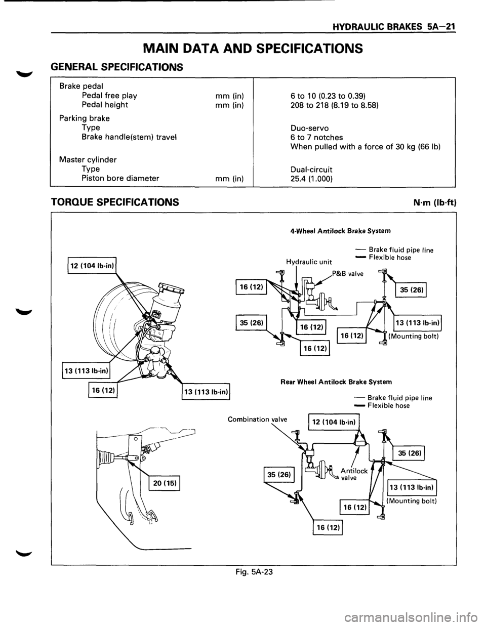
HYDRAULIC BRAKES 5A-21
MAIN DATA AND SPECIFICATIONS
GENERAL SPECIFICATIONS
Brake pedal
Pedal
free play
Pedal
height
Parking brake
Type Brake
handle(stem) travel
Master cylinder
Type
Piston bore diameter
TORQUE SPECIFICATIONS
mm (in)
mm (in)
mm (in)
13 (1131b·in)
Fig. 5A-23 6
to 10 (0.23 to 0.39)
208 to 218
(8.19 to 8.58)
Duo-servo
6 to 7 notches
When
pulled with a force of 30 kg (66 lb)
Dual-circuit
25.4 (1.000)
4-Wheel Antilock Brake System
N·m {lb·ft}
-Brake fluid pipe line -Flexible hose
Rear Wheel Antilock Brake System
-Brake fluid pipe line -Flexible hose
Page 344 of 1928
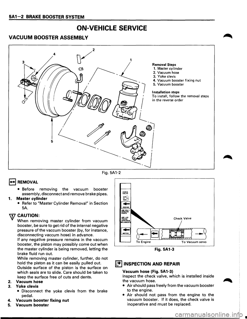
SA 1-2 BRAKE BOOSTER SYSTEM
ON-VEHICLE SERVICE
VACUUM BOOSTER ASSEMBLY
4
7
'
I ,
l_
Removal Steps 1. Master cylinder
2. Vacuum hose
3. Yoke clevis 4. Vacuum booster fixing nut 5. Vacuum booster
Installation steps
To install, follow the removal steps in the reverse order
®I
®'
Fig. 5A1-2
1••1 REMOVAL
• Before removing the vacuum booster
assembly, disconnect and remove brake pipes.
1. Master cylinder
• Refer to "Master Cylinder Removal" in Section
5A.
'\fCAUTION:
When removing master cylinder from vacuum
booster, be sure to get rid
of the internal negative
pressure
of the vaccum booster (by, for instance,
disconnecting vaccum hose) in advance.
If any negative pressure remains in the vaccum
booster, the piston may
possibly come out when
the master cylinder is being removed, letting the
brake
fluid run out.
While removing master cylinder, further, do not
hold the piston as it can be easily pulled out.
Outside surface of the piston is the surface on
which
seals are to slide. Care should be taken to
keep the surface free of cuts and dents.
2. Vacuum hose
3. Yoke clevis
• Disconnect the yoke clevis from the brake
pedal.
4. Vacuum booster fixing nut
5. Vacuum booster
Fig. 5A1-3
~ INSPECTION AND REPAIR
Vacuum hose (Fig. 5A1-3)
Inspect the check valve, which is installed inside
the vacuum hose.
• Air should pass freely from the vacuum booster
to the engine.
• Air should not pass from the engine to the
vacuum booster.
If it does, the check valve is
inoperative and
must be replaced.
•
Page 351 of 1928
DISC BRAKES 5A2-1
SECTION 5A2
DISC BRAKES
w CAUTION:
All brake attaching fasteners are an important attaching part in that they could affect performance of vital
parts and systems, and/or could result in major repair expense. They must be replaced with one of the same
part
number or with an equivalent part if replacement becomes necessary. Do not use replacement parts of
lesser quality or substitute design. Torque values must be used as specified during reassembly to assure
proper retention of these parts.
CONTENTS
General Description . . . . . . . . . . . . . . . . . . . . 5A2-1
Operation . . . . . . . . . . . . . . . . . . . . . . . . . . . . 5A2-1
Diagnosis
..................... See Section SA
On-Vehicle Service . . . . . . . . . . . . . . . . . . . . 5A2-2
Front Disc Brakes . . . . . . . . . . . . . . . . . . . . 5A2-2
Brake Pads
Inspection . .
. . . . . . . . . . . . 5A2-2
Brake Pads Replacement . . . . . . . . . . . 5A2-3
Servicing
the Rotor . . . . . . . . . . . . . . . . 5A2-4
Caliper Replacement . .
. . . . . . . . . . . . . 5A2-6
Rebuilding
the Caliper . . . . . . . . . . . . . 5A2-8 Rear
Disc Brakes .................... 5A2-1 0
Brake
Pads Inspection ............. 5A2-1 0
Brake Pads Replacement ........... 5A2-1 0
Servicing the Rotor ............... 5A2-12
Caliper Replacement .............. 5A2-14
Rebuilding the
Caliper ............. 5A2-17
Parking Brakes . . . . . . . . . . . . . . . .
See Section SC
Main Data and Specifications ........... 5A2-19
General Specifications ............... 5A2-19
Torque Specifications
............... 5A2-19
GENERAL DESCRIPTION
The disc brake assembly consists of a caliper, piston,
rotor, pad assembly and
support bracket. The caliper
assembly has a single bore and is mounted to the
support bracket with 2 mounting bolts. The support
bracket allows the caliper to move laterally against the
rotor. The
caliper is a one-piece casting with the
inboard side containing the piston bore. A square cut
rubber
seal is located in a groove in the piston bore
which provides the hydraulic seal between the piston
and the cylinder
wall.
NOTE:
• Replace all components included in repair kits
used
to service this caliper.
• Lubricate rubber parts with clean brake fluid to
ease assembly.
• If any hydraulic component is removed or
disconnected, it may be necessary to bleed all or
part of the brake system.
• Replace pads in axle sets only.
•
The torque values specified are for dry,
unlubricated fasteners.
• Perform service operation a clean bench free
from all mineral oil materials.
OPERATION
Hydraulic pressure, created by applying the brake
pedal, is converted by the caliper to a stopping force.
This force acts
equally against the piston and the
bottom of the caliper bore to move the piston outward
and to move (slide) the caliper inward resulting in a
clamping action on the rotor. This clamping action
forces the
linings against the rotor, creating friction to
stop the vehicle.
Page 353 of 1928
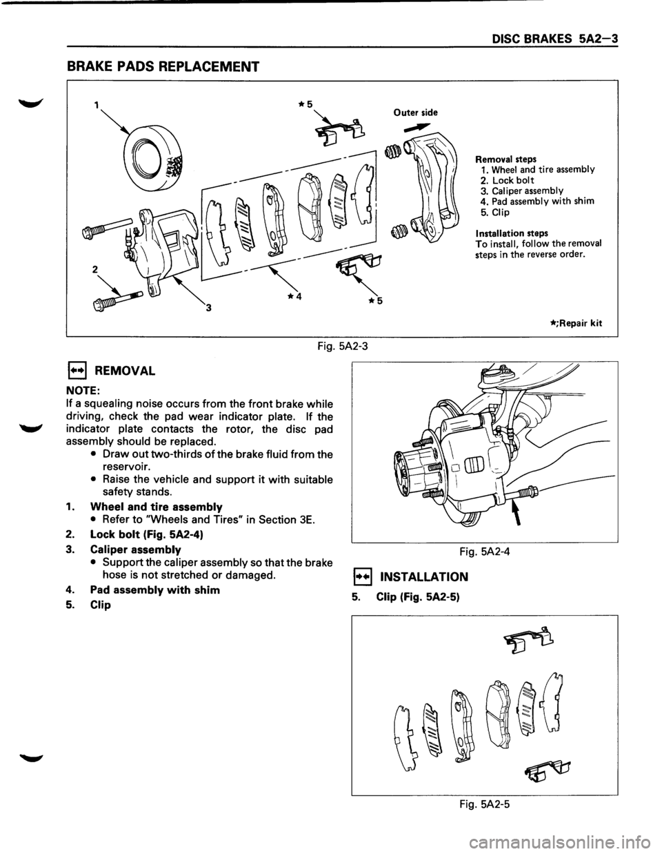
BRAKE PADS REPLACEMENT
1 Outer side
2
DISC BRAKES 5A2-3
Removal steps
1. Wheel and tire assembly
2. Lock
bolt 3. Caliper assembly
4. Pad assembly with shim
5. Clip
Installation
steps To install, follow the removal
steps in the reverse order.
*;Repair kit
Fig. 5A2-3
1••1 REMOVAL
NOTE:
If a squealing noise occurs from the front brake while
driving, check the pad wear indicator plate. If the
........., indicator plate contacts the rotor, the disc pad
assembly should be replaced.
•
Draw out two-thirds of the brake fluid from the
reservoir.
• Raise the vehicle and support it with suitable
safety stands.
1. Wheel and tire assembly
•
Refer to "Wheels and Tires" in Section 3E.
2. Lock bolt (Fig. 5A2-4)
3. Caliper assembly
• Support
the caliper assembly so that the brake
hose
is not stretched or damaged.
4. Pad assembly with shim
5. Clip
Fig. 5A2-4
1••1 INSTALLATION
5. Clip (Fig. 5A2-5)
Fig. 5A2-5
Page 354 of 1928
5A2-4 DISC BRAKES
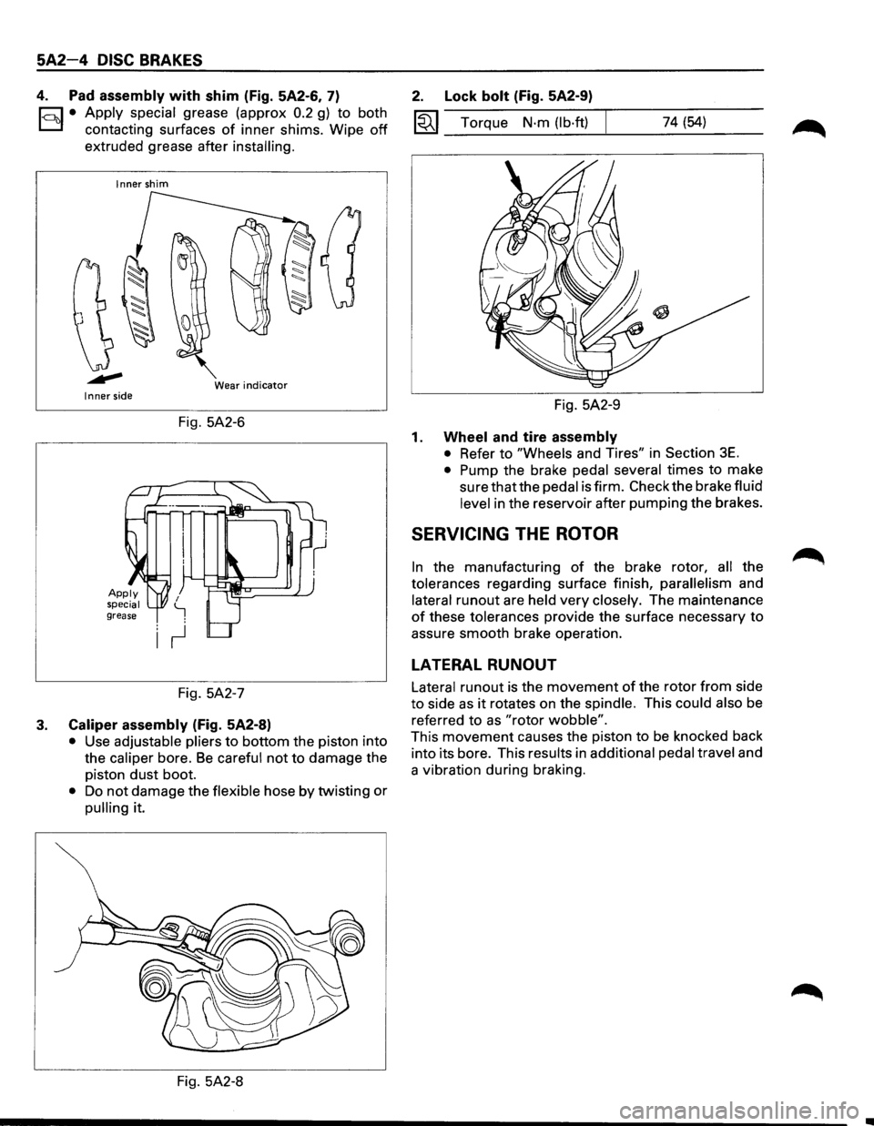
4. Pad assembly with shim (Fig. 5A2-6, 7)
1-c::~t:.l• Apply ~pecial grease (approx 0.2 g) to both
contactmg surfaces
of inner shims. Wipe off
extruded grease after installing.
Inner shim
Wear
indicator Inner side
Fig. 5A2-6
Fig. 5A2-7
3. Caliper assembly (Fig. 5A2-8)
• Use adjustable pliers to bottom the piston into
the
caliper bore. Be careful not to damage the
piston
dust boot.
• Do not damage the flexible hose by twisting or
pulling it.
Fig. 5A2-8
2. Lock bolt (Fig. 5A2-9)
1«1 Torque N·m (lb·ft) 74 (54)
Fig. 5A2-9
1. Wheel and tire assembly
• Refer to "Wheels and Tires" in Section 3E.
• Pump the brake pedal several times to make
sure that the pedal is firm. Check the brake fluid
level in the reservoir after pumping the brakes.
SERVICING THE ROTOR
In the manufacturing of the brake rotor, all the
tolerances regarding surface finish,
parallelism and
lateral
runout are held very closely. The maintenance
of these tolerances provide the surface necessary to
assure smooth brake operation.
LATERAL RUNOUT
Lateral runout is the movement of the rotor from side
to side as it rotates on the spindle. This could also be
referred
to as "rotor wobble".
This movement causes the piston to be knocked back
into its bore. This results in
additional pedal travel and
a vibration during braking.
Page 358 of 1928
5A2-1 0 DISC BRAKES
REAR DISC BRAKE
BRAKE PADS INSPECTION (Fig. 5A2-28)
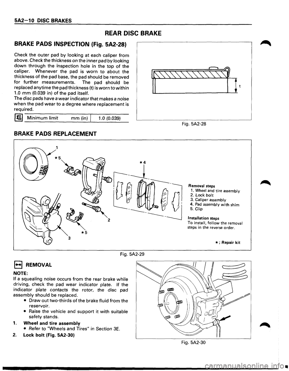
Check the outer pad by looking at each caliper from
above. Check the thickness on the inner pad by looking
down through the inspection hole in the top of the
caliper. Whenever the pad is worn to about the
thickness
of the pad base, the pad should be removed
for further measurements. The pad should be
replaced anytime the pad thickness (t) is worn to within
1.0 mm (0.039 in) of the pad itself. 'f'-~1~
The disc pads have a wear indicator that makes a noise
when the pad wear to a degree where replacement is
required.
~~~-M--in-im __ u_m_l-im--it _____ m_m--(i-n)-rl--,-.-0-(0-.-03_9_) ___
BRAKE PADS REPLACEMENT
EJ REMOVAL
NOTE:
1
*5
3
Fig. 5A2-29
If a squealing noise occurs from the rear brake while
driving, check the pad wear indicator plate. If the
indicator
plate contacts the rotor, the disc pad
assembly should be replaced.
•
Draw out two-thirds of the brake fluid from the
reservoir.
• Raise the vehicle and support it with suitable
safety stands.
1. Wheel and tire assembly
•
Refer to "Wheels and Tires" in Section 3E.
2. Lock bolt (Fig. 5A2-30) Fig.
5A2-28
Removal steps
1. Wheel and tire assembly 2. Lock bolt 3. Caliper assembly
4. Pad assembly with shim 5. Clip
Installation
steps
To
install, follow the removal steps in the reverse order.
* ; Repair kit
Fig. 5A2-30
•
Page 360 of 1928
5A2-12 DISC BRAKES
1. Wheel and tire assembly
• Refer to "Wheels and Tires" in Section 3E.
• Pump the brake pedal several times to
make sure that the pedal
is firm. Check the
brake fluid level in the reservoir after
pumping the brakes.
SERVICING THE ROTOR
In the manufacturing of the brake rotor, all the
tolerances regarding surface finish, parallelism and
lateral runout are held very closely. The maintenance
of these tolerances provide the surface necessary to
assure smooth brake operation.
LATERAL RUNOUT
Lateral runout is the movement of the rotor from side
to side as it rotates on the spindle. This could also be
referred
to as "rotor wobble".
This movement causes the piston to be knocked back
into its bore. This
results in additional pedal travel and
a vibration during braking.
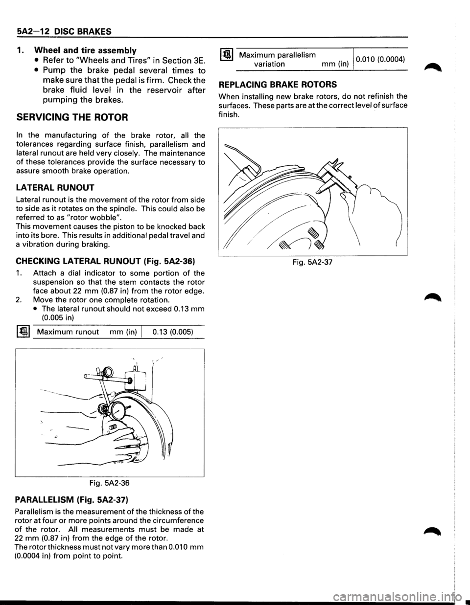
CHECKING LATERAL RUNOUT (Fig. 5A2-36)
1. Attach a dial indicator to some portion of the
suspension so
that the stem contacts the rotor
face about 22 mm (0.87 in) from the rotor edge.
2. Move the rotor one complete rotation.
• The lateral runout should not exceed 0.13 mm
(0.005 in)
~~~ Maximum runout mm (in) I 0.13 (0.005)
Fig. 5A2-36
PARALLELISM (Fig. 5A2-37)
Parallelism is the measurement of the thickness of the
rotor at
four or more points around the circumference
of the rotor. All measurements must be made at
22 mm (0.87 in) from the edge of the rotor.
The rotor thickness
must not vary more than 0.010 mm
(0.0004 in) from point to point.
Maximum parallelism variation mm (in) 0
·01 0 (0.000 4
)
REPLACING BRAKE ROTORS
When installing new brake rotors, do not refinish the
surfaces. These parts are at the correct
level of surface
finish.
Fig. 5A2-37
Page 362 of 1928
5A2-14 DISC BRAKES
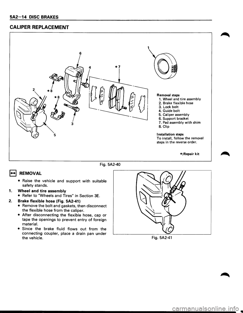
CALIPER REPLACEMENT
6
3
Fig. 5A2-40
1••1 REMOVAL
• Raise the vehicle and support with suitable
safety stands.
1. Wheel and tire assembly
• Refer to "Wheels and Tires" in Section 3E.
2. Brake flexible hose (Fig. 5A2-41)
• Remove the bolt and gaskets, then disconnect
the flexible hose
from the caliper.
• After disconnecting the flexible hose, cap or
tape the openings to prevent entry of foreign
material.
• Since the brake fluid flows out from the
connecting
coupler, place a drain pan under
the
vehicle.
1
Removal steps
1. Wheel and tire assembly
2. Brake flexible hose
3. Lock bolt 4. Guide bolt 5. Caliper assembly 6. Support bracket
7.
Pad assembly with shim
8.
Clip
Installation
steps
To install, follow the removal steps in the reverse order.
*;Repair kit
Fig. 5A2-41
Page 371 of 1928
REAR WHEEL ANTILOCK BRAKE SYSTEM 5A3-3
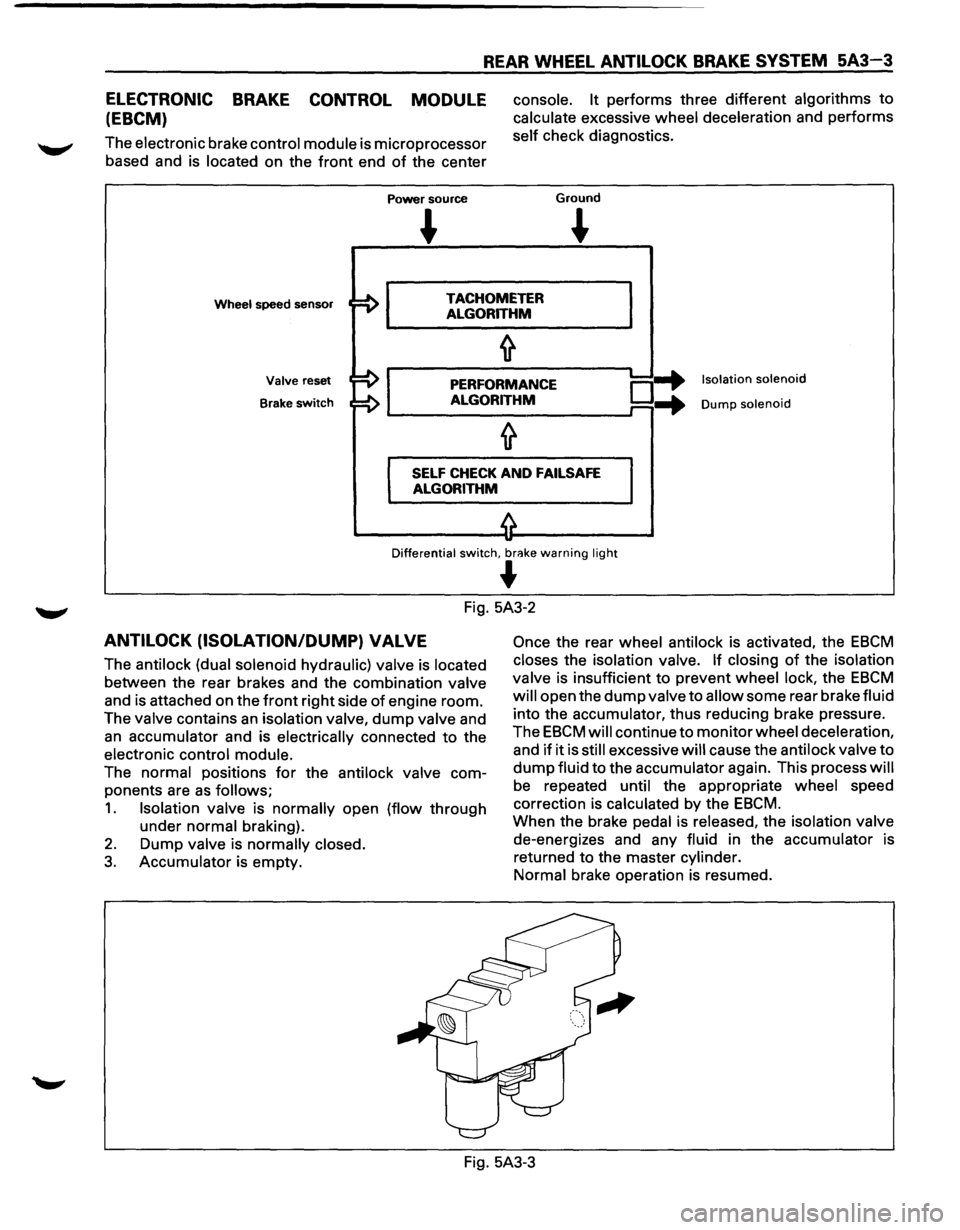
ELECTRONIC BRAKE CONTROL MODULE
(EBCM)
The electronic brake control module is microprocessor
based and is located on the
front end of the center
Power source
console. It performs three different algorithms to
calculate excessive wheel deceleration and performs
self check diagnostics.
Ground
~
Wheel speed sensor TACHOMETER
ALGORITHM
Valve reset
Brake
switch
PERFORMANCE
ALGORITHM o-+ ...
Isolation solenoid
Dump solenoid
SELF CHECK AND FAILSAFE
ALGORITHM
Differential switch, br<'!ke warning light
~
Fig. 5A3-2
ANTILOCK (ISOLATION/DUMP) VALVE
The antilock (dual solenoid hydraulic) valve is located
between the rear brakes and the combination valve
and is attached on the
front right side of engine room.
The valve contains
an isolation valve, dump valve and
an accumulator and is electrically connected to the
electronic control module.
The normal positions
for the antilock valve com
ponents are
as follows;
1. Isolation valve is normally open (flow through
under normal braking).
2. Dump valve is normally closed.
3. Accumulator is empty.
Once the rear wheel antilock is activated, the EBCM
closes the isolation valve. If closing of the isolation
valve is insufficient to prevent wheel lock, the
EBCM
will open the dump valve to allow some rear brake fluid
into the accumulator, thus reducing brake pressure.
The
EBCM will continue to monitor wheel deceleration,
and
if it is still excessive will cause the antilock valve to
dump fluid to the accumulator again. This process will
be repeated until the appropriate wheel speed
correction is calculated by the
EBCM.
When the brake pedal is released, the isolation valve
de-energizes and any fluid in the accumulator is
returned to the master cylinder.
Normal brake operation is resumed.
Fig. 5A3-3
Page 380 of 1928
5A3~12 REAR WHEEL ANTILOCK BRAKE SYSTEM
CHART C
Rr. ABS and Brake Lights 110N"
(No Flashout Code}
I • CHECK FOR BRAKE FLUID LEVEL AT THE RESERVOIR TANK.
I
I FLUID LEVEL LOW. I FLUID LEVEL OK.
I
• FIND AND REPAIR CAUSE OF LEAKAGE, AND RECHECK I • DISCONNECT THE HARNESS CONNECTOR FROM THE
SELF CHECK. COMBINATION SWITCH, AND START THE ENGINE, AND CHECK FOR LIGHTS.
I BOTH LIGHTS GO OFF. I BOTH LIGHTS REMAIN ON.
I
CHECK BRAKE SYSTEM FOR AIR IN LINES OR MECHANICAL I IGN. KEY OFF. DAMAGE, AND RECHECK THE SELF CHECK.
• DISCONNECT THE EBCM HARNESS CONNECTOR FROM EBCM, AND START THE ENGINE, AND CHECK uRr ABS" AND UBRAKE" LIGHTS.
I Rr. ABS LIGHT ON.
I
BRAKE LIGHT ON.
I I BOTH LIGHTS OFF. BRAKE LIGHT OFF. Rr. ABS LIGHT OFF.
I • CHECK FOR SHORT TO GROUND I • CHECK FOR SHORT TO GROUND I I
• CHECK FOR FUSE F-91N THE FUSE IN REAR ABS LIGHT WIRE. IN COMBINATION SWITCH WIRE. BOX OF ENGINE COMPARTMENT.
I I REPAIR
SHORT TO GROUND IN I REPAIR SHORT TO GROUND, AND J Continued on the next page REAR ABS LIGHT CIRCUIT, AND RECHECK THE SELF
CHECK.
RECHECK THE SELF CHECK.
EBCM -
Electronic Brake Control Module
•