brake fluid ISUZU TROOPER 1995 Owner's Guide
[x] Cancel search | Manufacturer: ISUZU, Model Year: 1995, Model line: TROOPER, Model: ISUZU TROOPER 1995Pages: 1928
Page 413 of 1928
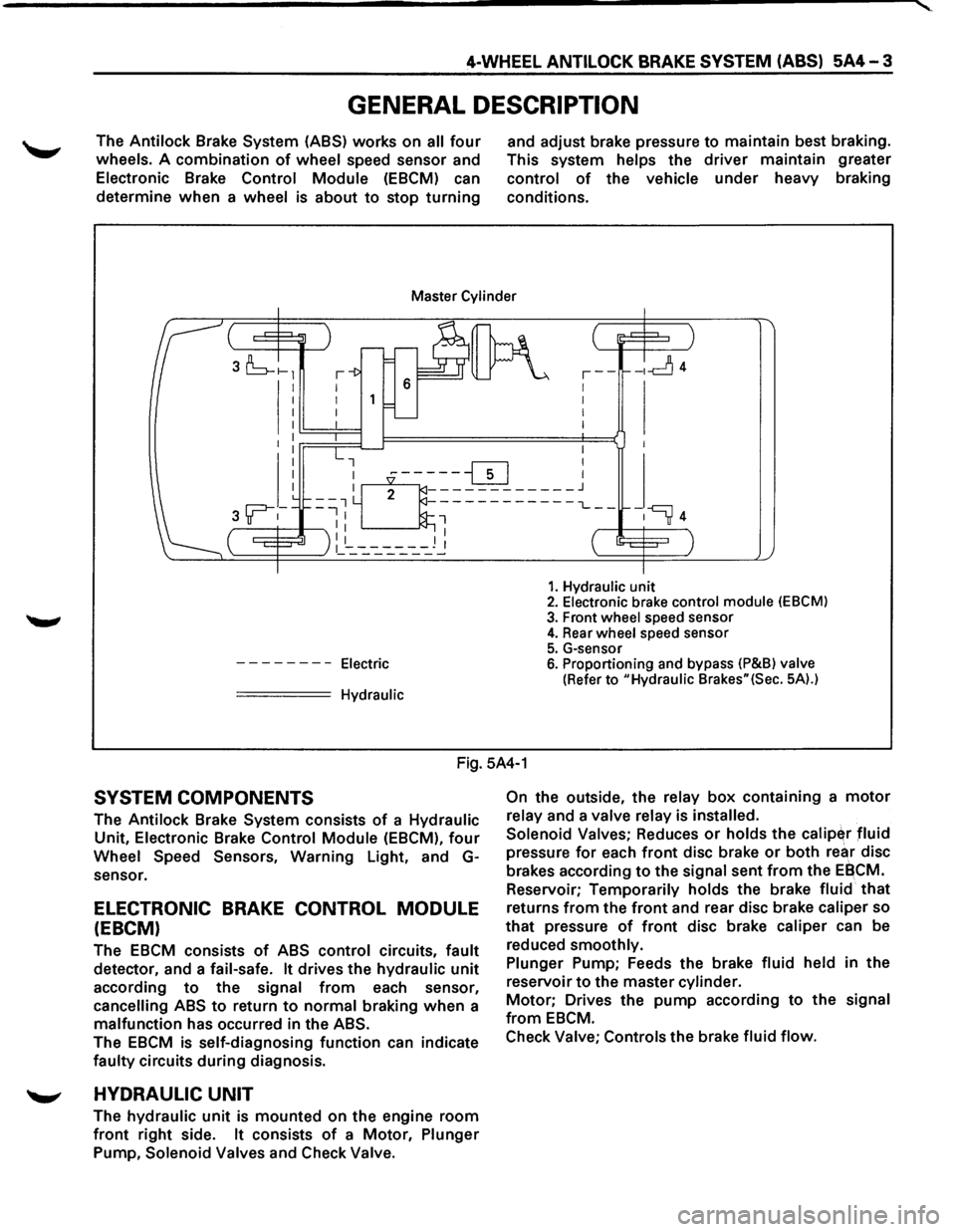
4-WHEEL ANTILOCK BRAKE SYSTEM (ABS) 5A4-3
GENERAL DESCRIPTION
The Antilock Brake System (ASS) works on all four
wheels. A combination of wheel speed sensor and
Electronic Brake Control Module (EBCM) can
determine
when a wheel is about to stop turning
and adjust brake pressure to maintain best braking.
This system
helps the driver maintain greater
control of the vehicle under heavy braking
conditions.
Master Cylinder
I I I I
--------Electric
===== Hydraulic
,--1 I
I
I
-ld4
1. Hydraulic unit 2. Electronic brake control module (EBCM)
3. Front wheel speed sensor 4. Rear wheel speed sensor
5. G-sensor 6. Proportioning and bypass (P&Bl valve
(Refer to "Hydraulic Brakes"(Sec. 5A).)
Fig. 5A4-1
SYSTEM COMPONENTS
The Antilock Brake System consists of a Hydraulic
Unit, Electronic Brake Control Module (EBCM), four
Wheel Speed Sensors, Warning Light, and G
sensor.
ELECTRONIC BRAKE CONTROL MODULE
(EBCM)
The EBCM consists of ABS control circuits, fault
detector, and a fail-safe. It drives the hydraulic unit
according to the signal from each sensor,
cancelling ABS to return to normal braking when a
malfunction has occurred in the ABS.
The EBCM is self-diagnosing function can indicate
faulty circuits during diagnosis.
'--" HYDRAULIC UNIT
The hydraulic unit is mounted on the engine room
front right side. It consists of a Motor, Plunger
Pump, Solenoid Valves and Check Valve. On
the
outside, the relay box containing a motor
relay and a valve relay is installed.
Solenoid Valves;
Reduces or holds the calip~r fluid
pressure for each front disc brake or both rear disc
brakes according
to the signal sent from the EBCM.
Reservoir;
Temporarily holds the brake fluid that
returns from the front and rear disc brake caliper so
that pressure of front disc brake caliper can be
reduced
smoothly.
Plunger
Pump; Feeds the brake fluid held in the
reservoir
to the master cylinder.
Motor; Drives the pump according to the signal
from EBCM.
Check
Valve; Controls the brake fluid flow.
Page 415 of 1928
4-WHEEL ANTILOCK BRAKE SYSTEM (ABS) 5A4-5
DIAGNOSIS
GENERAL INFORMATION
ABS troubles can be classified to two types, those
which can be detected by the ABS warning light
and those which can be detected as a vehicle
abnormality by the driver.
In either case, locate the fault in accordance with
the "BASIC DIAGNOSTIC FLOWCHART" and repair.
Please refer to Section 5A, 5A1, 5A2, 5C for the
diagnosis
of mechanical troubles such as brake
noise, brake
judder (brake pedal or vehicle vibration
felt when braking), uneven braking, and parking
brake
trouble.
ABS SYSTEM SERVICE PRECAUTIONS
Required Tools and Items
Box Wrench
• Brake Fluid
Special Tool
Some diagnosis procedures in this section require
the installation of a special tool.
PINOUT BOX
In order to prevent damage to the 35-pin Electronic
Brake
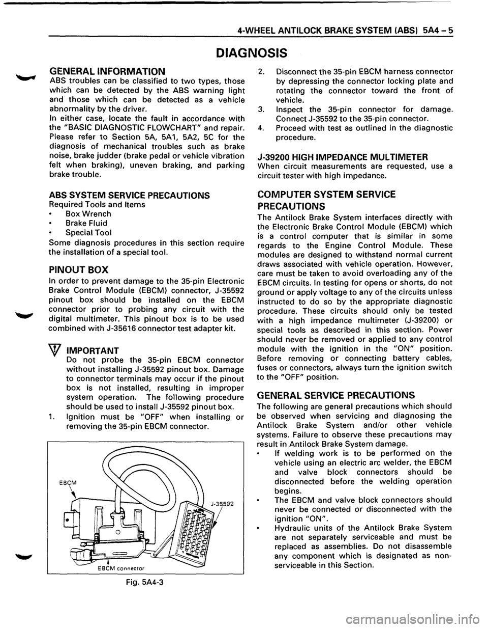
Control Module (EBCM) connector, J-35592
pinout box should be installed on the EBCM
connector prior to probing any circuit with the
digital
multimeter. This pinout box is to be used
combined with J-35616 connector test adapter kit.
W IMPORTANT
Do not probe the 35-pin EBCM connector
without installing J-35592 pinout box. Damage
to connector terminals may occur if the pinout
box is not installed, resulting in improper
system operation. The following procedure
should be used to install J-35592 pinout box.
1. Ignition must be "OFF" when installing or
removing the 35-pin EBCM connector.
Fig. 5A4-3
2. Disconnect the 35-pin EBCM harness connector
by depressing the connector locking plate and
rotating
the connector toward the front of
vehicle.
3. Inspect the 35-pin connector for damage.
Connect J-35592 to the 35-pin connector.
4. Proceed with test as outlined in the diagnostic
procedure.
J-39200 HIGH IMPEDANCE MUL TIMETER
When circuit measurements are requested, use a
circuit tester
with high impedance.
COMPUTER SYSTEM SERVICE
PRECAUTIONS
The Antilock Brake System interfaces directly with
the Electronic Brake Control Module (EBCM) which
is a
control computer that is similar in some
regards
to the Engine Control Module. These
modules are designed to withstand normal current
draws associated with vehicle operation. However,
care
must be taken to avoid overloading any of the
EBCM circuits. In testing for opens or shorts, do not
ground or apply voltage to any of the circuits unless
instructed to
do so by the appropriate diagnostic
procedure. These circuits should only be tested
with a high impedance multimeter (J-39200) or
special tools as described in this section. Power
should never be removed or applied to any control
module with the ignition in the "ON" position.
Before removing
or connecting battery cables,
fuses
or connectors, always turn the ignition switch
to the "OFF" position.
GENERAL SERVICE PRECAUTIONS
The following are general precautions which should
be observed when servicing and diagnosing the
Antilock Brake System and/or
other vehicle
systems. Failure
to observe these precautions may
result in Antilock Brake System damage.
If welding work is to be performed on the
vehicle using an electric arc welder, the EBCM
and valve block connectors should be
disconnected before the
welding operation
begins.
The
EBCM and valve block connectors should
never be connected or disconnected with the
ignition "ON".
Hydraulic units of the Antilock Brake System
are not separately serviceable and must be
replaced
as assemblies. Do not disassemble
any
component which is designated as non
serviceable in
this Section.
Page 454 of 1928
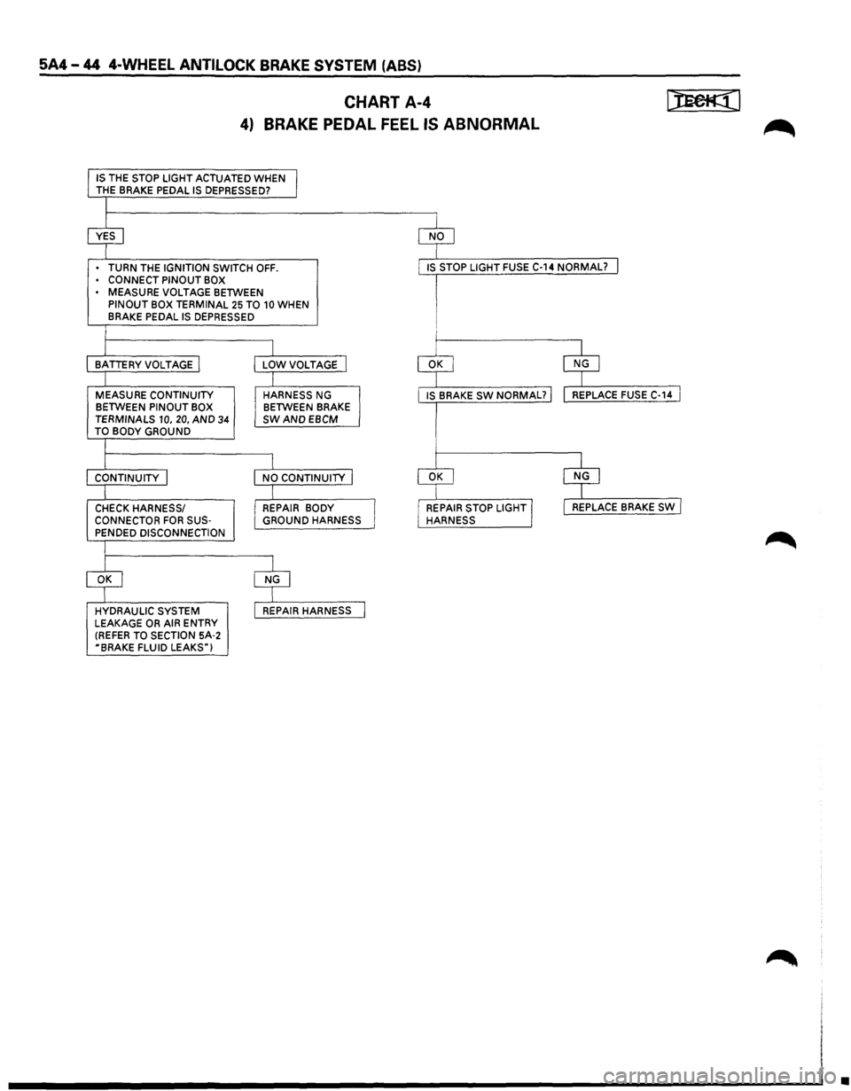
5A4-44 4-WHEEL ANTILOCK BRAKE SYSTEM (ASS)
CHART A-4
4) BRAKE PEDAL
FEEL IS ABNORMAL
IS THE STOP LIGHT ACTUATED WHEN
THE BRAKE PEDAL IS DEPRESSED?
TURN THE
IGNITION SWITCH OFF.
CONNECT PINOUT BOX
MEASURE VOLTAGE BETWEEN PINOUT BOX TERMINAL 25 TO 10 WHEN
BRAKE PEDAL IS DEPRESSED
MEASURE CONTINUITY BETWEEN PINOUT BOX
TERMINALS 10, 20, AND 34 TO BODY GROUND
CHECK HARNESS/
CONNECTOR
FOR SUSPENDED DISCONNECTION
HYDRAULIC SYSTEM
LEAKAGE OR AIR ENTRY (REFER TO SECTION 5A-2
"BRAKE FLUID LEAKS") HARNESS
NG
BETWEEN BRAKE
SWANDEBCM
•
Page 483 of 1928
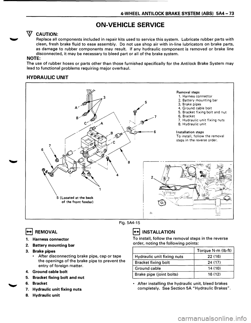
4-WHEEL ANTILOCK BRAKE SYSTEM (ABS) 5A4-73
ON-VEHICLE SERVICE
W CAUTION:
~ Replace all components included in repair kits used to service this system. Lubricate rubber parts with
clean, fresh brake fluid to ease assembly. Do not use shop air with in-line lubricators on brake parts,
as
damage to rubber components may result. If any hydraulic component is removed or brake line
disconnected,
it may be necessary to bleed part or all of the brake system.
NOTE:
The use of rubber hoses or parts other than those furnished specifically for the Anti lock Brake System may
lead to functional problems requiring major overhaul.
HYDRAULIC UNIT
5 (Located at the back
of the front fender) Removal
steps
1. Harness connector 2. Battery mounting bar 3. Brake pipes 4. Ground cable bolt 5. Bracket fixing bolt and nut 6. Bracket 7. Hydraulic unit fixing nuts 8. Hydraulic unit
Installation steps To install, follow the removal
steps in the reverse order.
1••1 REMOVAL
Fig. 5A4-15
I••IINSTALLATION
1. Harness connector
2. Battery mounting bar
3. Brake pipes
• After disconnecting brake pipe, cap or tape
the
openings of the brake pipe to prevent the
entry of foreign matter.
4. Ground cable bolt
5. Bracket fixing bolt and nut
6. Bracket
7. Hydraulic unit fixing nuts
8. Hydraulic unit
To install, follow the removal steps in the reverse
order,
noting the following points:
Torque
N·m Ob·ftl
Hydraulic unit fixing nuts 22 (16)
Bracket fixing bolt 24 (17)
Ground cable 14 (10)
Brake pipe (joint bolts) 16 (12)
• After installing the hydraulic unit, bleed brakes
completely.
See Section 5A "Hydraulic Brakes".
Page 632 of 1928
68 - 4 ENGINE COOLING
ON-VEHICLE SERVICE
DRAINING AND REFILLING COOLING
SYSTEM
Before draining the cooling system, inspect the sys
tem and perform any necessary service to ensure that
it is clean, does not leak and is in proper working
order. The Engine Coolant (EC) level should be be
tween the "MIN" and "MAX" lines of reserve tank
when the engine is cold. If low, check for leakage and
add
EC up to the "MAX" line. There should not be any
excessive deposit of rust or scales around the radiator
cap
or radiator filler hole, and the EC should also be
free
from oil. Replace the EC if excessively dirty.
1. Completely drain the cooling system by opening
the drain petcock at the bottom of the radiator.
2. Remove the radiator cap.
W WARNING
To avoid the danger of being burned, do not
remove the cap while the engine and radiator
are still hot. Scalding fluid and steam can be
blown out under pressure.
3. Disconnect all hoses from the EC reserve tank.
Scrub and clean the inside of the reserve tank with
soap and water. Flush it well with clean water,
then drain it. Install the reserve tank and hoses.
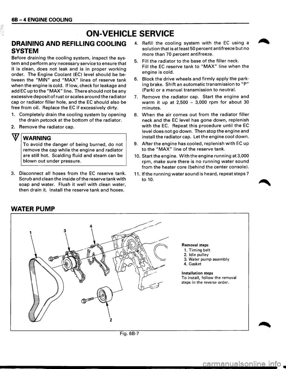
WATER PUMP
3
j
2
4. Refill the cooling system with the EC using a
solution that is at least 50 percent antifreeze but no
more than 70 percent antifreeze.
5. Fill the radiator to the base of the filler neck.
Fill the EC reserve tank to "MAX" line when the
engine is cold.
6. Block the drive wheels and firmly apply the park
ing brake.
Shift an automatic transmission to "P"
(Park) or a manual transmission to neutral.
7. Remove the radiator cap. Start the engine and
warm it up at 2,500 -3,000 rpm for about 30
minutes.
8. When the air comes out from the radiator filler
neck and the EC level has gone down, replenish
with the EC. Repeat this procedure until the EC
level does not go down. Then stop the engine and
install the radiator cap. Let the engine cool down.
9. After the engine has cooled, replenish with EC up
to the "MAX" line of the reserve tank.
10. Start the engine. With the engine running at 3,000
rpm, make sure there is no running water sound
from the heater core (behind the center console).
11. If the running water sound is heard, repeat steps 7
to 10.
Removal steps
1. Timing
belt 2. Idle pulley 3. Water pump assembly
4. Gasket
Installation steps To install, follow the removal steps in the reverse order.
Fig. 6B-7
•
Page 657 of 1928
ENGINE ELECTRICAL 601-3
ON-VEHICLE SERVICE
BATTERY CHARGING
Observe the following safety precautions when
charging the battery:
1. Never attempt to charge the battery when the
fluid level is below the lower level line on the
side
of the battery. In this case, the battery
must be replaced.
2. Pay close attention to the battery during the
charging procedure.
Battery charging
should be discontinued or the
rate
of charge reduced if the battery feels hot
to the touch.
Battery charging
should be discontinued or the
rate
of charge reduced if the battery begins to
gas or spew electrolyte from the vent holes.
3. In order to more easily view the hydrometer
blue dot or ring, it may be necessary to jiggle
or tilt the battery.
4. Battery temperature can have a great effect on
battery charging capacity.
5. The sealed battery used on this vehicle may be
either quick-charged or slow-charged in the
same manner
as other batteries.
Whichever method you decide
to use, be sure
that you
completely charge the battery. Never
partially charge the battery.
JUMP STARTING
JUMP STARTING WITH AN AUXILIARY
(BOOSTER)
BATTERY
W CAUTION:
Never push or tow the vehicle in an attempt to
start it.
Serious damage to the emission sys
tem as
well as other vehicle parts will result.
Treat both the discharged battery and the
booster battery
with great care when using
jumper cables. Carefully follow the jump start
ing procedure, being
careful at all times to
avoid sparking.
wwARNING:
Failure to carefully follow the jump starting
procedure
could result in the following:
1. Serious personal injury, particulaly to your
eyes.
2. Property damage from a battery explo
sion, battery acid, or an electrical fire.
3. Damage to the electronic components of
one or both vehicles particularly.
Never expose the battery to an open flame or elec
trical
spark. Gas generated by the battery may catch
fire
or explode.
Remove any rings, watches, or other jewelry before
working around the battery. Protect
your eyes by
wearing
an approved set of goggles.
Never allow battery fluid to come in contact with
your eyes or skin.
Never
allow battery fluid to come in contact with
fabrics or painted surfaces.
Battery
fluid is a highly corrosive acid.
Should battery fluid come in contact with your eyes,
skin, fabric, or a painted surface,
immediately and
thoroughly rinse the affected area with clean tap
water. Never
allow metal tools or jumper cables to come
in contact with the positive battery
terminal, or any
other
metal surface of the vehicle. This will protect
against a short circuit.
Always keep batteries out of the reach of young
children.
JUMP STARTING PROCEDURE
1. Set the vehicle parking brake.
If the vehicle is equipped with an automatic
transmission,
place the selector lever in the
"PARK" position.
If the vehicle is equipped with a manual trans
mission
place the shift lever in the "NEUTRAL"
position.
Turn
"OFF" the ignition.
Turn
"OFF" all lights and any other accessory
requiring
electrical power.
2. Look at the built-in hydrometer.
If the indication area of the built-in hydrometer
is
completely clear, do not try to jump start.
3. Attach the end of one jumper cable to the posi
tive
terminal of the booster battery.
Attach the other end
of the same cable to the
positive
terminal of the discharged battery.
Do not allow the vehicles to touch each other.
This
will cause a ground connection, effectively
neutralizing
the charging procedure.
Be sure that the booster battery has a 12 volt
rating.
4. Attach one end of the remaining cable to the
negative
terminal of the booster battery.
Attach the other end
of the same cable to a
solid engine ground (such as the air condition
ing compressor bracket or the generator
mounting bracket)
of the vehicle with the dis
charged battery.
This ground connection must be at
least 450
mm (18 in) from the battery of the vehicle
whose battery is being charged.
Page 892 of 1928
7 A-20 AUTOMATIC TRANSMISSION (4L30-E)
CHECKING TRANSMISSION FLUID
LEVEL AND CONDITION
Checking fluid level and condition (color and odor)
at
regular intervals will provide early diagnosis
information about the transmission. This inform
ation may be used to correct a condition that, if not
detected early, could result in major transmission
repairs.
IMPORTANT: When new, automatic transmission
fluid is red in color. As the vehicle is driven, the
transmission
fluid will begin to look darker in color.
The
color may eventually appear light brown.
A DARK
brown color with burnt odor may indicate
excessive
fluid deterioration and signal a need for
fluid change.
FLUID LEVEL
When adding
or changing fluid, use only DEXRON
®-Ill.
Refer to the Maintenance and Lubrication (Section 0
of this manual) for maintenance information and
servicing
interval.
\f CAUTION: DO NOT OVERFILL
Overfilling will cause foaming, loss ~f fluid,
abnormal shifting and possible damage to
the transmission.
1. Start engine and drive vehicle until normal AfT
oil operating temperature is reached:
NOTE: The automatic transmission fluid level
must be checked with the vehicle at normal
A/T oil operating temperature: 75 TO 85°C
(167 TO 185°F) MEASURED WITH TECH1 SCAN
TOOL.
Temperature will greatly affect transmission
fluid level.
If the vehicle is not at normal AfT oil operating
temperature and the proper checking
procedures are
not followed, the result could
be a false reading of the fluid level indicator
and
an incorrect adjustment of the fluid level.
2. Park vehicle on level ground.
3. Move gear selector to "Park".
4. Apply parking brake and block wheels.
5. Allow vehicle to idle for 3 minutes with all
accessories turned off.
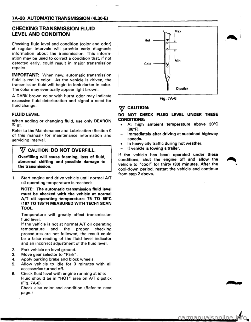
6. Check fluid level with engine running at idle:
Fluid should
be in "HOT" area on AfT dipstick
(Fig. 7A-6).
Check also color and condition (Refer to next
page.)
Hot
Cold ---IIU 0
0
Min
Dipstick
Fig. 7A-6
\f CAUTION:
DO NOT CHECK FLUID LEVEL UNDER THESE
CONDITIONS: •
At high ambient temperature above 30°C
(86°F).
Immediately after driving at sustained highway
speeds.
• In heavy city traffic during hot weather.
If vehicle is towing a trailer.
If the vehicle has been operated under these
conditions,
shut the engine off and allow the
vehicle to "cool" for thirty (30) minutes. After the
cool-down period, restart the vehicle and continue
from step 2 above.
'~I
......
Page 896 of 1928
7 A-24 AUTOMATIC TRANSMISSION (4l30-E)
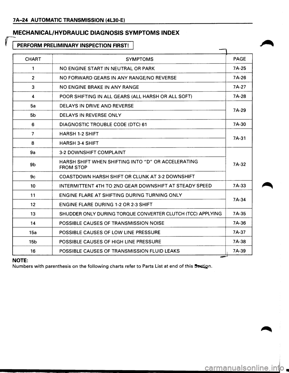
MECHANICAL/HYDRAULIC DIAGNOSIS SYMPTOMS INDEX
rr PERFORM PRELIMINARY INSPECTION FIRST! , -
CHART SYMPTOMS PAGE
1
NO ENGINE START IN NEUTRAL OR PARK 7A-25
2
NO FORWARD GEARS IN ANY RANGE/NO REVERSE 7A-26
3
NO ENGINE BRAKE IN ANY RANGE 7A-27
4
POOR SHIFTING IN ALL GEARS (ALL HARSH OR ALL SOFT) 7A-28
Sa DELAYS IN DRIVE AND REVERSE 7A-29
5b DELAYS
IN REVERSE ONLY
6 DIAGNOSTIC TROUBLE CODE (DTC) 61 7A-30
7 HARSH 1-2
SHIFT 7A-31
8 HARSH 3-4
SHIFT
9a 3-2 DOWNSHIFT
COMPLAINT
9b HARSH SHIFT WHEN SHIFTING INTO "D" OR ACCELERATING 7A-32 FROM STOP
9c COASTDOWN HARSH SHIFT OR CLUNK AT 3-2 DOWNSHIFT
10 INTERMITTENT 4TH TO 2ND GEAR DOWNSHIFT AT STEADY SPEED 7A-33
11 ENGINE FLARE AT SHIFTING
DURING TURNING ONLY 7A-34
12 ENGINE FLARE DURING 1-2 OR 2-3 SHIFT
13 SHUDDER ONLY DURING TORQUE CONVERTER CLUTCH (TCC) APPLYING 7A-35
14
POSSIBLE CAUSES OF TRANSMISSION NOISE 7A-36
15a
POSSIBLE CAUSES OF LOW LINE PRESSURE 7A-37
15b
POSSIBLE CAUSES OF HIGH LINE PRESSURE 7A-38
16
POSSIBLE CAUSES OF TRANSMISSION FLUID LEAKS It 7A-39
= -NOTE:
Numbers with parenthesis on the following charts refer to Parts List at end of this ~n.
•
Page 913 of 1928
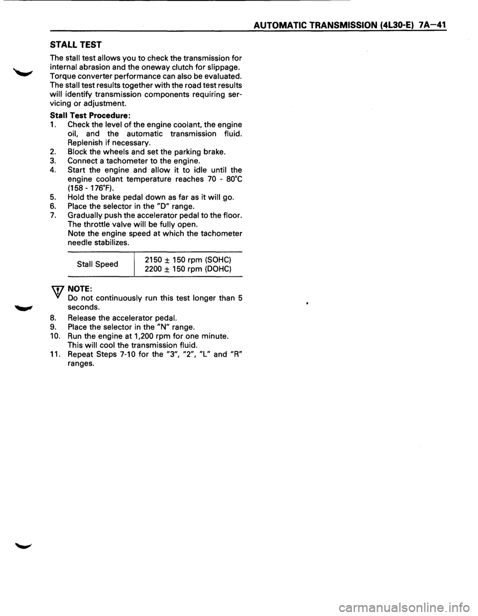
STALL TEST
The stall test allows you to check the transmission for
internal abrasion and the oneway clutch for slippage.
Torque converter performance can also be evaluated.
The
stall test results together with the road test results
will identify transmission components requiring ser
vicing or adjustment.
Stall Test Procedure:
1. Check the level of the engine coolant, the engine
oil, and the automatic transmission fluid.
Replenish
if necessary.
2. Block the wheels and set the parking brake.
3. Connect a tachometer to the engine.
4. Start the engine and allow it to idle until the
engine coolant temperature reaches
70 -8o·c
(158 -176.F).
5. Hold the brake pedal down as far as it will go.
6. Place the selector in the "D" range.
7. Gradually push the accelerator pedal to the floor.
The throttle valve
will be fully open.
Note the engine speed at which the tachometer
needle stabilizes.
Stall Speed
\fl NOTE:
2150 ± 150 rpm (SOHC)
2200 ± 150 rpm (DOHC)
VI Do not continuously run this test longer than 5
........, seconds.
8. Release the accelerator pedal.
9. Place the selector in the "N" range.
10. Run the engine at 1,200 rpm for one minute.
This
will cool the transmission fluid.
11. Repeat Steps 7-10 for the "3", "2", "L" and "R"
ranges.
AUTOMATIC TRANSMISSION (4L30-E) 7A-41
Page 914 of 1928
7 A-42 AUTOMATIC TRANSMISSION (4L30-E)
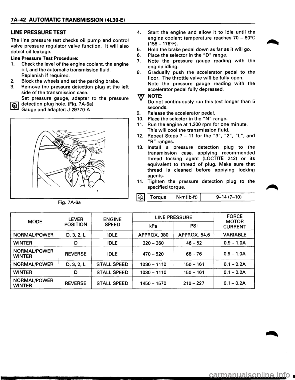
LINE PRESSURE TEST
The line pressure test checks oil pump and control
valve
pressure regulator valve function. It will also
detect oil leakage.
Line Pressure Test Procedure:
1. Check the level of the engine coolant, the engine
oil, and the automatic transmission fluid.
Replenish
if required.
2. Block the wheels and set the parking brake.
3. Remove the pressure detection plug at the left
side of the transmission case.
Set pressure gauge, adapter
to the pressure
l"iC\1 detection plug hole. (Fig. 7 A-6a)
~ Gauge and adapter: J-29770-A
Fig. 7A-6a
LEVER ENGINE
MODE
POSITION
SPEED
NORMAL/POWER D,3,2, L IDLE
WINTER D IDLE
NORMAL/POWER REVERSE IDLE WINTER
NORMAL/POWER
D,3,2,L STALL SPEED
WINTER D STALL SPEED
NORMAL/POWER REVERSE STALL SPEED WINTER
4.
5.
6.
7.
8.
9.
10.
11.
Start the engine and allow it to idle until the
engine
coolant temperature reaches 70 -80°C
(158-176°F).
Hold
the brake pedal down as far as it will go.
Place the selector in the "D" range.
Note the pressure gauge reading
with the
engine
idling.
Gradually
push the accelerator pedal to the
floor. The throttle valve will be fully open.
Note the pressure gauge reading
with the
accelerator
pedal fully depressed.
NOTE:
Do not continuously run this test longer than 5
seconds.
Release the accelerator pedal.
Place
the selector in the "N" range.
Run the engine at
1,200 rpm for one minute.
This
will cool the transmission fluid.
12. Repeat Steps 7-11 for the "3", "2", "L", and
"R" ranges.
13.
Install a pressure detection plug to the
transmission case,
applying recommended
thread
locking agent (LOCTITE 242) or its
equivalent to thread
of plug. Make sure that
thread is cleaned before applying locking
agents.
14. Tighten the pressure detection plug to the
specified torque.
~~~ Torque N·mOb·ft) / 9-14 (7-10)
LINE
PRESSURE FORCE
MOTOR kPa PSI CURRENT
APPROX. 380 APPROX. 54.6 VARIABLE
320-360 46-52 0.9 -1.0A
470-520 68-76 0.9 -1.0A
1030-1110 150-161 0.1-0.2A
1030-1110 150-161 0.1-0.2A
1450-1570 210-227 0.1-0.2A
•