brake fluid ISUZU TROOPER 1995 Repair Manual
[x] Cancel search | Manufacturer: ISUZU, Model Year: 1995, Model line: TROOPER, Model: ISUZU TROOPER 1995Pages: 1928
Page 1375 of 1928
CHASSIS ELECTRICAL 8-185
REAR WHEEL ANTI-LOCK BRAKE SYSTEM (RWAL)
GENERAL DESCRIPTION
The circuit consists of the starter switch, stoplight switch (vehicle w/o cruise control), brake switch (vehicle
w/cruise control). RWAL controller, RWAL speed sensor, RWAL valve, brake differential switch, 4WD switch,
parking brake
SW, indicator light (RWAL, 4WD, BRAKE), and test connector.
In this system, when the service brake is applied the RWAL controller judges the wheel rotation difference
signals which have been sent from the RWAL speed sensor at the rear axle differential. The anti-lock valves
control
the brake fluid pressure which is applied to the rear wheels to prevent the wheels from locking.
When starting the engine, the RWAL indicator in the instrument panel lights up at the same time as the brake
indicator
to inform the driver that the system is operating normally. (The light goes off after two seconds.)
Refer
to Section 5A3, "RWAL (REAR WHEEL ANTI-LOCK BRAKE SYSTEM)" for detail.
Page 1478 of 1928
8-288 CHASSIS ELECTRICAL
METER AND WARNING/INDICATOR LIGHT
GENERAL DESCRIPTION
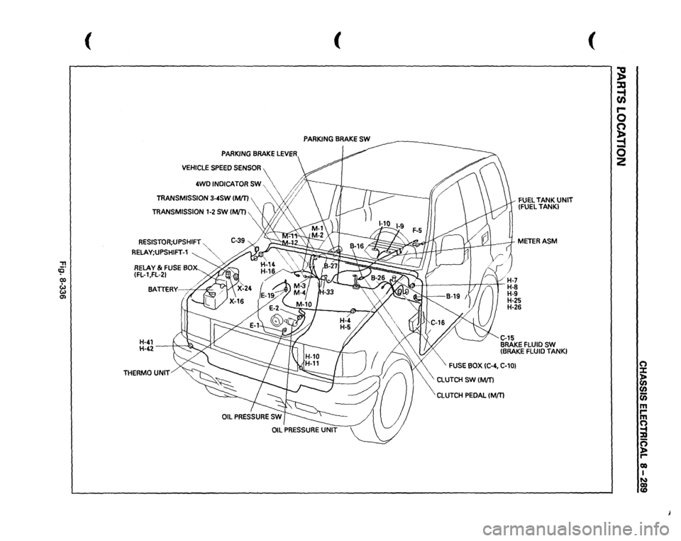
The circuit consists of the starter switch, meter assembly, vehicle speed sensor, clutch switch, transmission
switch, lighting switch,
turn signal switch, thermo unit, oil pressure unit, Engine Control Module, fuel tank unit,
4WD
SW, oil pressure switch, parking brake switch, brake fluid switch, seat belt switch and illumination
controller.
The meter ASM contains the speedometer, tachometer, voltmeter, engine coolant temperature gauge, oil
pressure gauge, fuel gauge and warning/indicator lights.
The meter warning/indicator lights and
their bulb sockets are a unit, they are installed from the back of the
speedometer assembly.
Page 1479 of 1928
::!!
(
(
PARKING
BRAKE
SW
PARKING
BRAKE
LEVER
VEHICLE
SPEED
SENSOR
4WD
INDICATOR
SW,
~
' '
/;~>
TRANSMISSION
3-4SW
IMJT)
"vf;/
RESISTOR;UPSHIFT
."
RELAY;UPSHIFT-1
~":'""
RELAY
& FUSE
BOX-_
(FL-1
,FL-21 BA.
TTERY--.;:;4"~
H-41 H-42
-----;1-"'.,.,-~
THERMO
UNIT
FUEL
TANK
UNIT
(FUEL
TANK)
METERASM
~
16)
1 /
1
(
H-7
/'1'-J
? I n
H-8 H-9 H-25
H-26 C..15 BRAKE
FLUID
SW
(BRAKE
FLUID
TANK}
FUSE
BOX
IC-4,
C-10}
\CLUTCH
SW
(M/T)
CLUTCH
PEDAL
(Mm
(
~ ::xs ~ r-0 0 ~ -0 2
(") :X: ~ en (i) m rm (") ~ g roo I ~
Page 1485 of 1928
CHASSIS ELECTRICAL 8-295
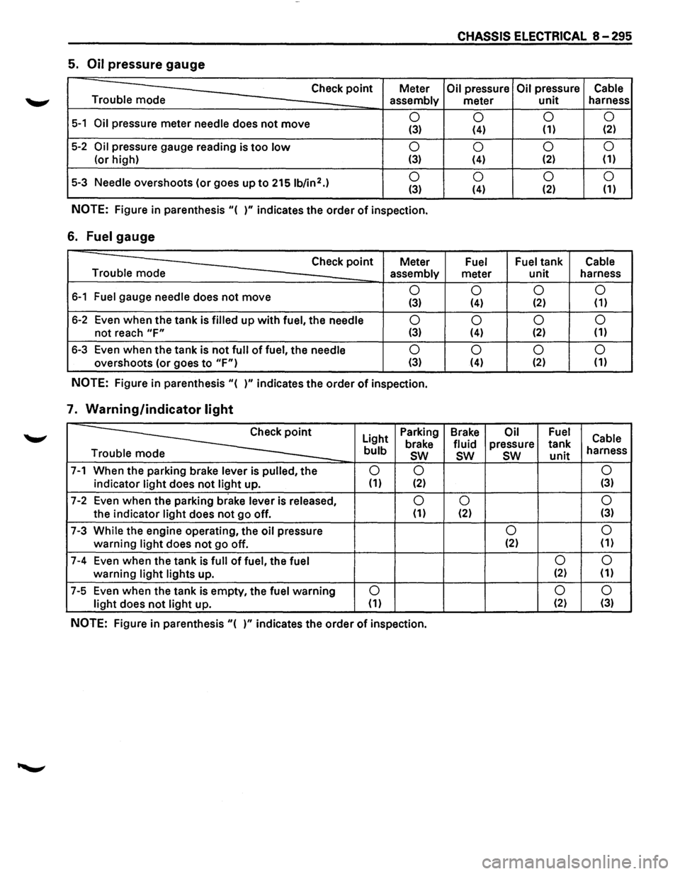
5. Oil pressure gauge
Check point Meter Oil pressure Oil pressure Cable
Trouble mode
assembly meter unit harness
5-1 Oil pressure meter needle does not move 0
0 0
0 (3) (4) (1) (2)
5-2 Oil pressure
gauge reading is too low 0
0 0
0
(or
high) (3) (4) (2) (1)
5-3 Needle overshoots
(or goes up to 2151b/in2.) 0
0 0 0 (3) (4) (2)
(1)
NOTE: Figure
in parenthesis "( )" indicates the order of inspection.
6. Fuel gauge
Check point Meter Fuel Fuel tank Cable
Trouble mode assembly
meter unit harness
6-1 Fuel gauge needle does not move 0
0 0 0 (3) (4) (2) (1)
6-2 Even when the tank is filled up with fuel, the needle 0
0 0
0
not reach "F" (3) (4) (2)
(1)
6-3
Even when the tank is not full of fuel, the needle 0
0 0
0
overshoots (or goes to "F") (3) (4) (2) (1)
NOTE: Figure
in parenthesis "( )" indicates the order of inspection.
7. Warning/indicator light
~
Light Parking
Brake Oil Fuel Cable brake fluid pressure tank bulb sw sw sw unit harness
e
7-1 When the parking brake lever is pulled, the 0 0 0
indicator light does not light up. (1) (2) (3)
7-2 Even
when the parking brake lever is released, 0 0 0
the indicator light does not go off. (1) (2) (3)
7-3 While the engine operating,
the oil pressure 0 0
warning light does not go
off. (2)
(1)
7-4 Even
when the tank is full of fuel, the fuel 0 0
warning light lights
up. (2) (1)
7-5 Even
when the tank is empty, the fuel warning 0 0
0
light does not light up. (1) (2)
(3)
NOTE: Figure in parenthesis "( )" indicates the order of inspection.
Page 1502 of 1928
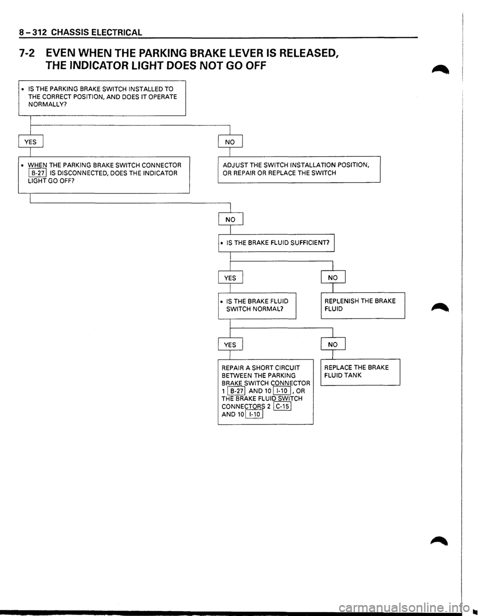
8-312 CHASSIS ELECTRICAL
7-2 EVEN WHEN THE PARKING BRAKE LEVER IS RELEASED,
THE
INDICATOR LIGHT DOES NOT GO OFF
• IS THE PARKING BRAKE SWITCH INSTALLED TO
THE CORRECT POSITION, AND DOES IT OPERATE NORMALLY?
I
I I
YES I NO I
I I
• WHEN THE PARKING BRAKE SWITCH CONNECTOR ADJUST THE SWITCH INSTALLATION POSITION,
I B-27lls DISCONNECTED, DOES THE INDICATOR OR REPAIR OR REPLACE THE SWITCH
LIGHT GO
OFF?
I
I
NO I
I
• IS THE BRAKE FLUID SUFFICIENT? J
I
I I
YES I NO J
I
I
• IS THE BRAKE FLUID REPLENISH THE
BRAKE
SWITCH NORMAL? FLUID
I
I
l
YES I NO I
I I
REPAIR A SHORT CIRCUIT REPLACE THE
BRAKE
BETWEEN THE
PARKING FLUID TANK
BRAKE SWITCH
CONNECTOR
1 I B-271 AND 10 [I!QJ' OR THE BRAKE FLUID SWITCH
CONNECTORS
21 C-151 AND10[IlQ]
Page 1523 of 1928
1. Fuel tank
• Refer to fuel tank removal steps in Section 6C
"ENGINE FUEL."
2. Fuel tank unit
• Disconnect the connectors.
• Remove the five screws.
B INSTALLATION
To install, follow the removal steps in the reverse
order.
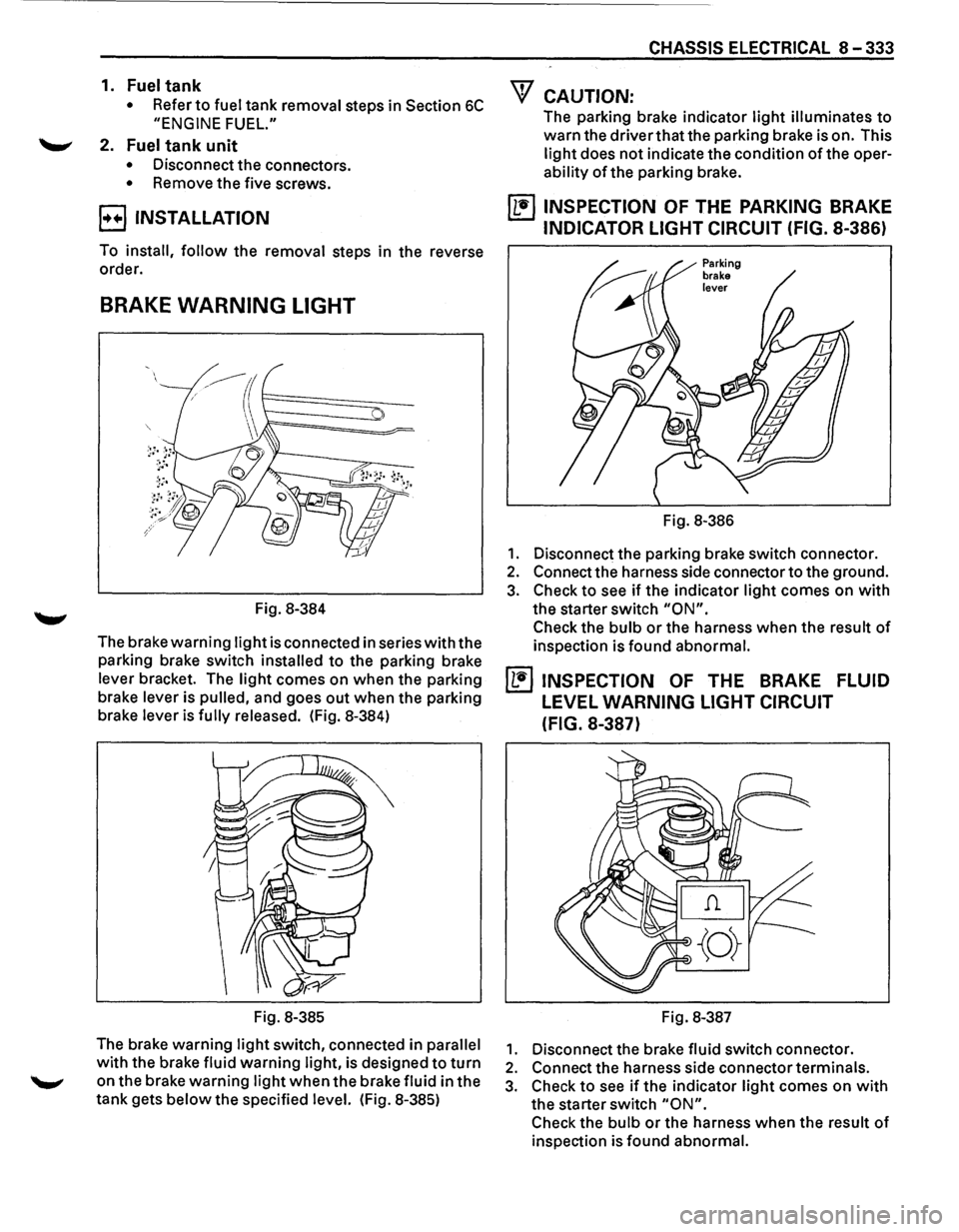
BRAKE WARNING LIGHT
Fig. 8-384
The brake
warning light is connected in series with the
parking brake switch
installed to the parking brake
lever bracket. The
light comes on when the parking
brake lever is
pulled, and goes out when the parking
brake lever is
fully released. (Fig. 8-384)
Fig. 8-385
The brake warning
light switch, connected in parallel
with the brake fluid warning light, is designed to turn
on the brake warning light when the brake fluid in the
tank gets
below the specified level. (Fig. 8-385)
CHASSIS ELECTRICAL 8-333
"f CAUTION:
The parking brake indicator light illuminates to
warn the driver that the parking brake is on. This
light does not indicate the condition of the oper
ability of the parking brake.
~ INSPECTION OF THE PARKING BRAKE
INDICATOR LIGHT CIRCUIT (FIG. 8-386)
Fig. 8-386
1. Disconnect the parking brake switch connector.
2. Connect the harness side connector to the ground.
3. Check to see if the indicator light comes on with
the starter switch "ON".
Check the bulb or the harness when the result of
inspection is found abnormal.
~ INSPECTION OF THE BRAKE FLUID
LEVEL WARNING LIGHT CIRCUIT
(FIG.
8-387)
Fig. 8-387
1. Disconnect the brake fluid switch connector.
2. Connect the harness side connector terminals.
3. Check to see if the indicator light comes on with
the starter switch "ON".
Check the bulb or the harness when the result of
inspection is found abnormal.
Page 1524 of 1928
8-334 CHASSIS ELECTRICAL
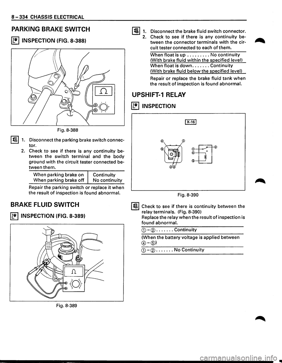
PARKING BRAKE SWITCH
~ INSPECTION (FIG. 8-388)
Fig. 8-388
I ti!!.l 1. Disconnect the parking brake switch connec
tor.
2. Check to see if there is any continuity be
tween the switch terminal and the
body
ground with the circuit tester connected be
tween them.
When parking brake on
Continuity
When parking brake off No continuity
Repair the parking switch
or replace it when
the result
of inspection is found abnormal.
BRAKE FLUID SWITCH
~ INSPECTION (FIG. 8-389)
Fig. 8-389
1311. Disconnectthebrakefluidswitchconnector.
2. Check to see if there is any continuity be-...-...
tween the connector terminals with the cir--..
cuit tester connected to each of them.
When float is up ......... No continuity
(With brake fluid within the specified level)
When float is
down ....... Continuity
(With brake fluid
below the specified level)
Repair
or replace the brake fluid tank when
the result
of inspection is found abnormal.
UPSHIFT-1 RELAY
~ INSPECTION
®ijf ®
-UJ
ill®
Fig. 8-390
131 Check to see if there is continuity between the
relay terminals. (Fig.
8-390)
Replace the relay when the result of inspection is
found abnormal.
G)-® ....... Continuity
(When the battery voltage is applied between
@-@)
G)-® ....... No Continuity
..