stop start ISUZU TROOPER 1995 Owner's Manual
[x] Cancel search | Manufacturer: ISUZU, Model Year: 1995, Model line: TROOPER, Model: ISUZU TROOPER 1995Pages: 1928
Page 447 of 1928
!! co U1 )> "" I .... w
(
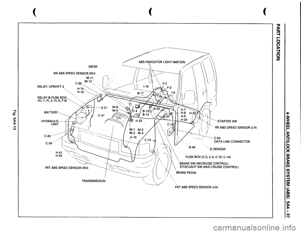
EBCM
RR
ABS SPEED SENSOR
(RHl
.
RELAY:
UPSHIFT-2
""·,'-....."
M-11_
. ·r·---
..
C-39
M-12"-~.·
··..
> .. , ,·
~'
...
,
~~~~~
~.-·
& FUSE
BOX
· ••.
(FL-1,
FL-2, FL-6,
F-9~
'•
BATTERY HYDRAULIC
--+1--.-.
UNIT
C-33
--~----
C-34.
H-41
H-42
TRANSMISSION
(
~·~ rl r
( STARTER
SW
RR
ABS SPEED SENSOR
(LH)
\~· \'
-.
.
B-46
' G SENSOR
\
FUSE
BOX (C-3, C-4, C-10, C-14)
BRAKE
SW
(W/CRUISE CONTROL)
STOPLIGHT SW
(W/0
CRUISE CONTROL)
BRAKE PEDAL FRT
ABS
SPEED SENSOR
(LH)
(
"V )> ~ r-0 s 5 2
.... :e ::I: m
m r-l> 2 ~ r-0 0 ~ CCI ~ ~ m ~ Cl) -t m s: ~ ~ c.n t I w .....
Page 457 of 1928
4-WHEEL ANTILOCK BRAKE SYSTEM (ASS) 5A4-47
DIAGNOSTIC TROUBLE CODES (DTCs)
When the warning light in the meter remains ON, the EBCM stores the fault identification and disables the
.........,.. ABS.
1. How to display and erase DTCs:
NOTE:
• If DTCs are not displayed, harness BB 14 may be disconnected. Repair the harness and try DTC
display again.
• DTCs can be displayed also by TECH 1. For further details, see "MODE F2: TROUBLE CODE" in this
section.
(1)
How to start DTC display:
• Confirm
that the vehicle has come to a complete stop (with the wheels standing still) and that the
brake pedal is not depressed. (Unless these two condition are satisfied, DTC display cannot be
started.)
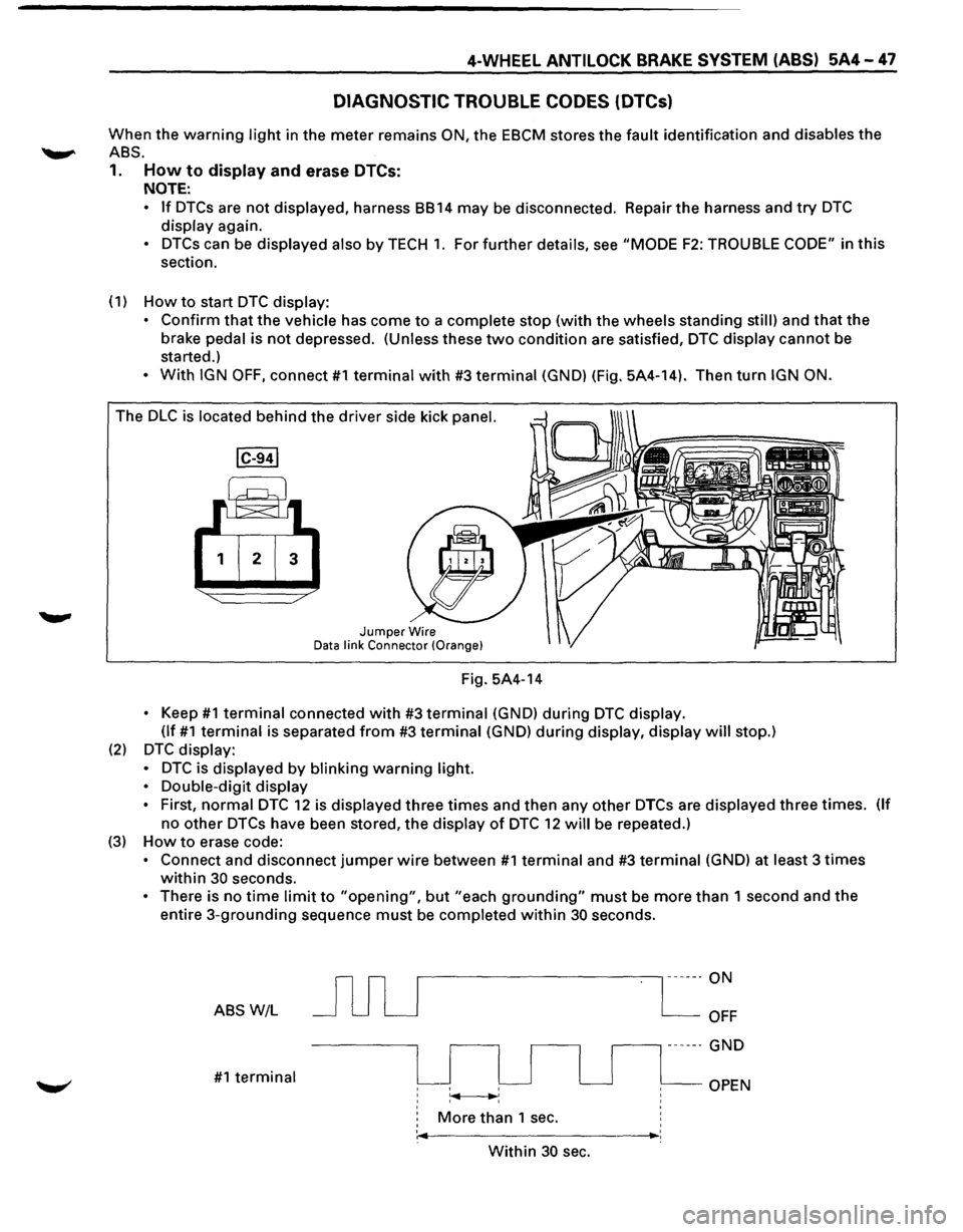
• With IGN OFF, connect #1 terminal with #3 terminal (GND) (Fig. 5A4-14). Then turn IGN ON.
The DLC is located behind the driver side kick panel.
1 2 3
Jumper Wire Data link Connector (Orange}
Fig. 5A4-14
• Keep #1 terminal connected with #3 terminal (GND) during DTC display.
(If
#1 terminal is separated from #3 terminal (GND) during display, display will stop.)
(2) DTC display:
•
DTC is displayed by blinking warning light.
•
Double-digit display
•
First, normal DTC 12 is displayed three times and then any other DTCs are displayed three times. (If
no other DTCs have been stored, the display of DTC 12 will be repeated.)
(3) How to erase code:
• Connect and disconnect jumper wire between #1 terminal and #3 terminal (GND) at least 3 times
within 30 seconds.
• There is no time limit to "opening", but "each grounding" must be more than 1 second and the
entire 3-grounding sequence must be completed within 30 seconds.
ABS W/L
#1 terminal
r---------------, ------ON
More than 1 sec.
OFF
.--------, ------ GND
OPEN
' ,._ _________ ,_:
Within 30 sec.
Page 514 of 1928
6-16 ENGINE DIAGNOSIS
ENGINE OIL PRESSURE CHECK
1. Check for dirt, gasoline or water in the engine
oil.
a. Change the oil if dirt, gasoline, or water
are present.
b. Check the viscosity of the oil.
c. Change the oil if the viscosity is outside
the specified standard.
d. Refer to the "Maintenance and Lubrication"
section of this manual.
2. Check the engine oil level.
The level should fall somewhere between the
"ADD" and the "FULL" marks on the oil level
dipstick.
If the oil level does not reach the "ADD" mark
on the
oil level dipstick, engine oil must be
added.
3. Remove the oil pressure unit.
4. Install an oil pressure gage.
5. Start the engine and allow the engine to reach
normal operating temperature (About 80°C).
6. Measure the oil pressure.
Oil pressure should be:
7. Stop the engine.
392-550 kPa (56.9-80.4 psi)
at
3000 rpm.
8. Remove the oil pressure gage.
9. Install the oil pressure unit.
10. Start the engine and check for leaks.
m ... cw
•
Page 632 of 1928
68 - 4 ENGINE COOLING
ON-VEHICLE SERVICE
DRAINING AND REFILLING COOLING
SYSTEM
Before draining the cooling system, inspect the sys
tem and perform any necessary service to ensure that
it is clean, does not leak and is in proper working
order. The Engine Coolant (EC) level should be be
tween the "MIN" and "MAX" lines of reserve tank
when the engine is cold. If low, check for leakage and
add
EC up to the "MAX" line. There should not be any
excessive deposit of rust or scales around the radiator
cap
or radiator filler hole, and the EC should also be
free
from oil. Replace the EC if excessively dirty.
1. Completely drain the cooling system by opening
the drain petcock at the bottom of the radiator.
2. Remove the radiator cap.
W WARNING
To avoid the danger of being burned, do not
remove the cap while the engine and radiator
are still hot. Scalding fluid and steam can be
blown out under pressure.
3. Disconnect all hoses from the EC reserve tank.
Scrub and clean the inside of the reserve tank with
soap and water. Flush it well with clean water,
then drain it. Install the reserve tank and hoses.
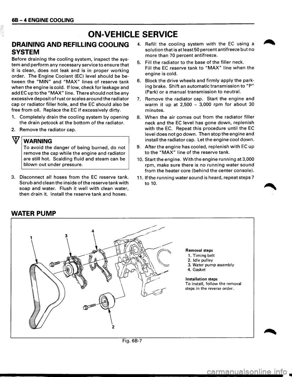
WATER PUMP
3
j
2
4. Refill the cooling system with the EC using a
solution that is at least 50 percent antifreeze but no
more than 70 percent antifreeze.
5. Fill the radiator to the base of the filler neck.
Fill the EC reserve tank to "MAX" line when the
engine is cold.
6. Block the drive wheels and firmly apply the park
ing brake.
Shift an automatic transmission to "P"
(Park) or a manual transmission to neutral.
7. Remove the radiator cap. Start the engine and
warm it up at 2,500 -3,000 rpm for about 30
minutes.
8. When the air comes out from the radiator filler
neck and the EC level has gone down, replenish
with the EC. Repeat this procedure until the EC
level does not go down. Then stop the engine and
install the radiator cap. Let the engine cool down.
9. After the engine has cooled, replenish with EC up
to the "MAX" line of the reserve tank.
10. Start the engine. With the engine running at 3,000
rpm, make sure there is no running water sound
from the heater core (behind the center console).
11. If the running water sound is heard, repeat steps 7
to 10.
Removal steps
1. Timing
belt 2. Idle pulley 3. Water pump assembly
4. Gasket
Installation steps To install, follow the removal steps in the reverse order.
Fig. 6B-7
•
Page 637 of 1928
E!) INSTALLATION
6. Radiator assembly
• Install cushion rubbers on both sides of radia
tor bottom.
• Install radiator assembly with hose, taking
care
not to damage the radiator core with a fan
blade.
5. Bracket
• Support the radiator uppertankwith the bracket
and secure the radiator.
4. Reserve tank hose
3. Fan guide, lower
2. Radiator hose
• Connect inlet hose and outlet hose to the
engine.
1. Oil cooler hose (A/T)
• Connect oil cooler hose for automatic trans-
mission.
• Connect battery ground cable.
• Pour engine coolant.
• Pour engine coolant up to filler neck of radia
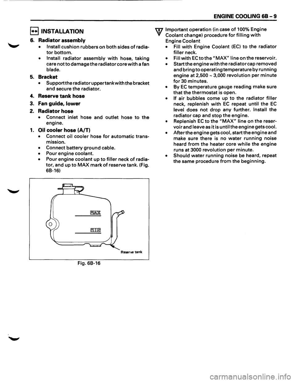
tor, and up to MAX mark of reserve tank. (Fig.
68-16)
Reserve tank
Fig. 68-16
ENGINE COOLING 68-9
U7 Important operation (in case of 100% Engine
V Coolant change) procedure for filling with
Engine Coolant
• Fill
with Engine Coolant (EC) to the radiator
filler neck.
• Fill with EC to the "MAX" line on the reservoir.
• Start the engine with the radiator cap removed
and bring
to operating temperature by running
engine at
2,500-3,000 revolution per minute
for 30 minutes.
• By EC temperature gauge reading make sure
that the thermostat is open.
• If air bubbles come up to the radiator filler
neck, replenish with EC repeat until the EC
level does not drop any further. Install the
radiator cap and stop the engine.
• Replenish EC to the "MAX" line on the reser
voir and leave as it is until the engine gets cool.
• After the engine gets cool, start the engine and
make sure there is no
water running noise
heard
from the heater core while the engine
runs
at 3000 revolution per minute.
• Should water running noise be heard, repeat
the same procedure from the beginning.
Page 646 of 1928
![ISUZU TROOPER 1995 Owners Manual 6C - 4 ENGINE FUEL
I1!]1NSPECTION
After installation, start engine and check for fuel leak
age.
IN-TANK FUEL FILTER
The filter is located on the lower end of fuel pickup
tube in the fuel tank](/img/61/57183/w960_57183-645.png "ISUZU TROOPER 1995 Owners Manual 6C - 4 ENGINE FUEL
I1!]1NSPECTION
After installation, start engine and check for fuel leak
age.
IN-TANK FUEL FILTER
The filter is located on the lower end of fuel pickup
tube in the fuel tank")
6C - 4 ENGINE FUEL
I1!]1NSPECTION
After installation, start engine and check for fuel leak
age.
IN-TANK FUEL FILTER
The filter is located on the lower end of fuel pickup
tube in the fuel tank. It prevents dirt from entering the
fuel pipe and also stops water unless the filter is
completely submerged in the water. It is a self-cleaning
type, not requiring scheduled maintenance. Excess
water and sediment in the tank restricts fuel supply to
the engine, resulting in engine stop. In such a case, the
tank
must be cleaned throughly.
FUEL PUMP FLOW TEST
If reduction of fuel supply is suspected, perform
checking as follows.
Preparation:
• Make sure that there is fuel in the tank.
• With the engine running, check the fuel feed
pipe and hose
from fuel tank to injector for
evidence of leakage.
Retighten, if pipe or hose connection is loose.
Also,
check pipes and hoses for squashing or
clogging.
1. Receive the hose from fuel feed pipe with a clean
container, and check for fuel pump flow rate.
2. Connect the pump relay terminals with a jumper
wire as shown and start the fuel pump to measure
delivery. (Fig. 6C-4)
W CAUTION:
Never generate sparks when connecting a jumper
wire.
Fig. 6C-4
Delivery Delivery
15 seconds 0.38
liters minimum
If the measure value is out of standard, conduct the
pressure test.
Pressure test
For the pressure test to the fuel system, see Section 6E
"Fuel Control System".
II
Page 659 of 1928
CRANKING SYSTEM 6D2 - 1
SECTION 602
CRANKING SYSTEM
CONTENTS
General Description ....................... .
Diagnosis
.................................... .
On-Vehicle Service ........................ . 6D2-1
6D2-3
6D2-8 Unit
Repair.................................... 6D2-9
Main Data and Specifications
............ 6D2-17
Torque Specifications
...................... 6D2-18
GENERAL DESCRIPTION
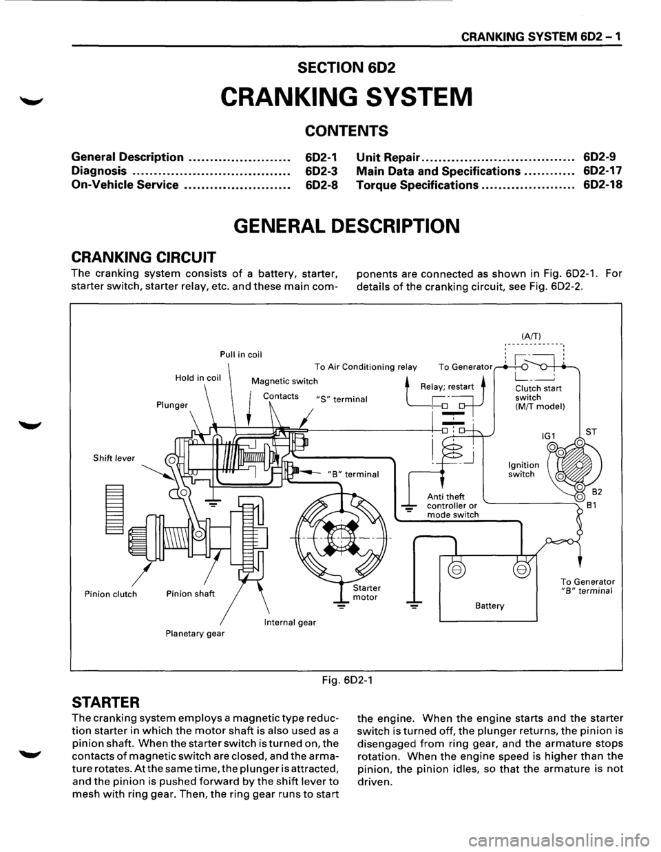
CRANKING CIRCUIT
The cranking system consists of a battery, starter,
starter switch, starter relay, etc. and these main com-
Pull in coil
Hold
in coil
Plunger
Shift lever
Pinion clutch
Internal
gear
Planetary gear
ponents are connected as shown in Fig. 602-1. For
details of the cranking circuit, see Fig. 602-2.
Anti theft controller or mode switch
Battery
(AfT} '-------------. ' '
To Generator "B" terminal
Fig. 602-1
STARTER
The cranking system employs a magnetic type reduc
tion starter in which the motor shaft is also used as a
pinion shaft. When the starter switch is turned on, the
contacts of magnetic switch are closed, and the arma
ture rotates. At the same time, the plunger is attracted,
and the pinion is pushed forward by the shift lever to
mesh with ring gear. Then, the ring gear runs to start
the engine. When the engine starts and the starter
switch is turned off, the plunger returns, the pinion is
disengaged from ring gear, and the armature stops
rotation. When the engine speed is higher than the
pinion, the pinion idles, so that the armature is not
driven.
Page 665 of 1928
CRANKING SYSTEM 602 -7
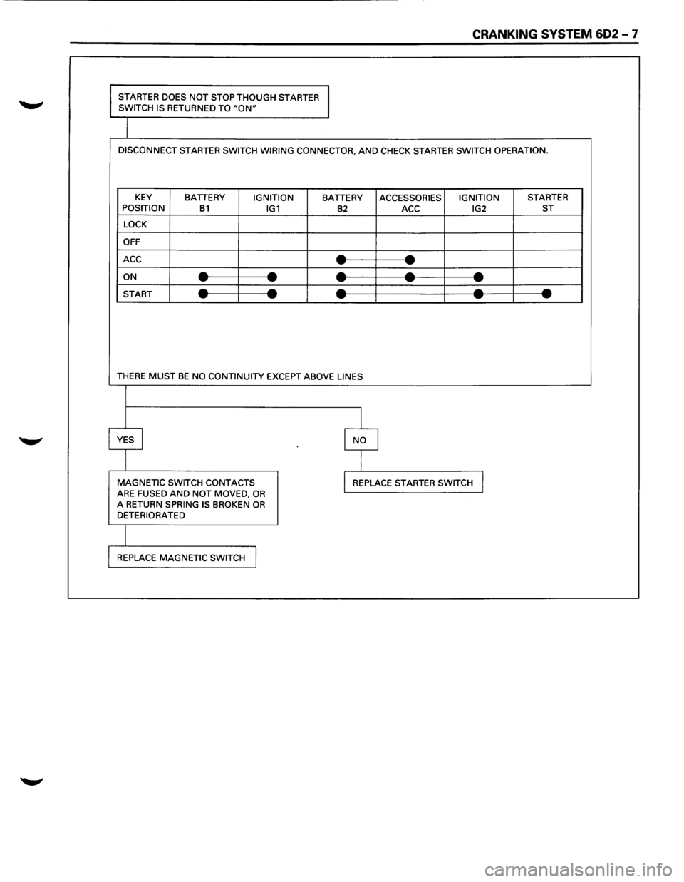
STARTER DOES NOT STOP THOUGH STARTER
SWITCH IS RETURNED TO "ON"
DISCONNECT STARTER SWITCH WIRING CONNECTOR, AND CHECK STARTER SWITCH OPERATION.
KEY
BATTERY IGNITION BATTERY ACCESSORIES IGNITION STARTER
POSITION B1 IG1 B2 ACC IG2 ST
LOCK
OFF
ACC
--- -ON ----------START ----------
THERE MUST BE NO CONTINUITY EXCEPT ABOVE LINES
I
YES I I NO
I
MAGNETIC SWITCH CONTACTS I REPLACE STARTER SWITCH J ARE FUSED AND NOT MOVED, OR A RETURN SPRING IS BROKEN OR DETERIORATED
REPLACE
MAGNETIC SWITCH I
Page 679 of 1928
CHARGING SYSTEM 603 -3
DIAGNOSIS
GENERAL ON-VEHICLE INSPECTION
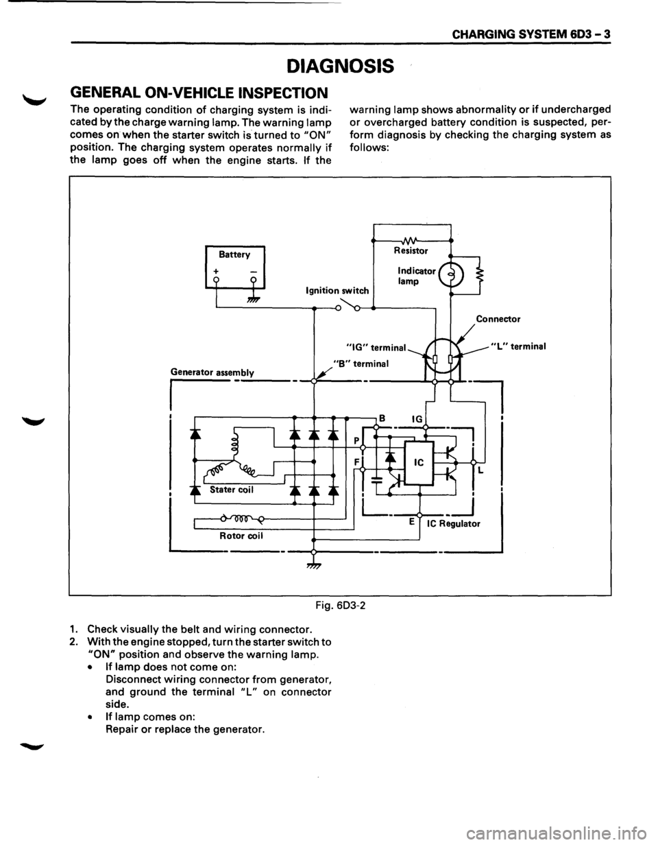
The operating condition of charging system is indi
cated
by the charge warning lamp. The warning lamp
comes on when the starter switch is turned to "ON"
position. The charging system operates normally if
the lamp goes off when the engine starts. If the
Battery
+
warning lamp shows abnormality or if undercharged
or overcharged battery condition is suspected, per
form diagnosis by checking the charging system as
follows:
Resistor
Ignition switch
"B" terminal
Fig. 603-2
1. Check visually the belt and wiring connector.
2. With the engine stopped, turn the starter switch to
"ON" position and observe the warning lamp.
• If lamp does not come on:
Disconnect
wiring connector from generator,
and
ground the terminal "L" on connector
side.
• If lamp comes on:
Repair
or replace the generator.
Connector
"L" terminal
l
Page 680 of 1928
603 - 4 CHARGING SYSTEM
ON-VEHICLE SERVICE
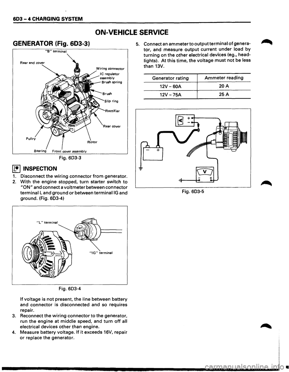
GENERATOR (fig. 603-3}
"B" terminal
Pullry
Fig. 603-3
~ INSPECTION
Wiring connector
I C regulator
assembly
Brush spring
ifier
Rear cover
1. Disconnect the wiring connector from generator.
2. With the engine stopped, turn starter switch to
"ON" and connect a voltmeter between connector
terminal Land ground or between terminaiiG and
ground. (Fig. 603-4)
"IG" terminal
Fig. 603-4
If voltage is not present, the line between battery
and
connector is disconnected and so requires
repair.
3. Reconnect the wiring connector to the generator,
run the
engine at middle speed, and turn off all
electrical
devices other than engine.
4. Measure battery voltage. If it exceeds 16V, repair
or replace the generator.
5. Connect an ammeter to outputterminal of genera
tor, and measure output current under load by
turning on the other electrical devices (eg., head
lights). At this time, the voltage must not be less
than 13V.
Generator rating
Ammeter reading
12V-60A 20A
12V -75A 25A
Fig. 603-5
•