ISUZU TROOPER 1995 Workshop Manual
TROOPER 1995
ISUZU
ISUZU
https://www.carmanualsonline.info/img/61/57183/w960_57183-0.png
ISUZU TROOPER 1995 Workshop Manual
Page 311 of 1928
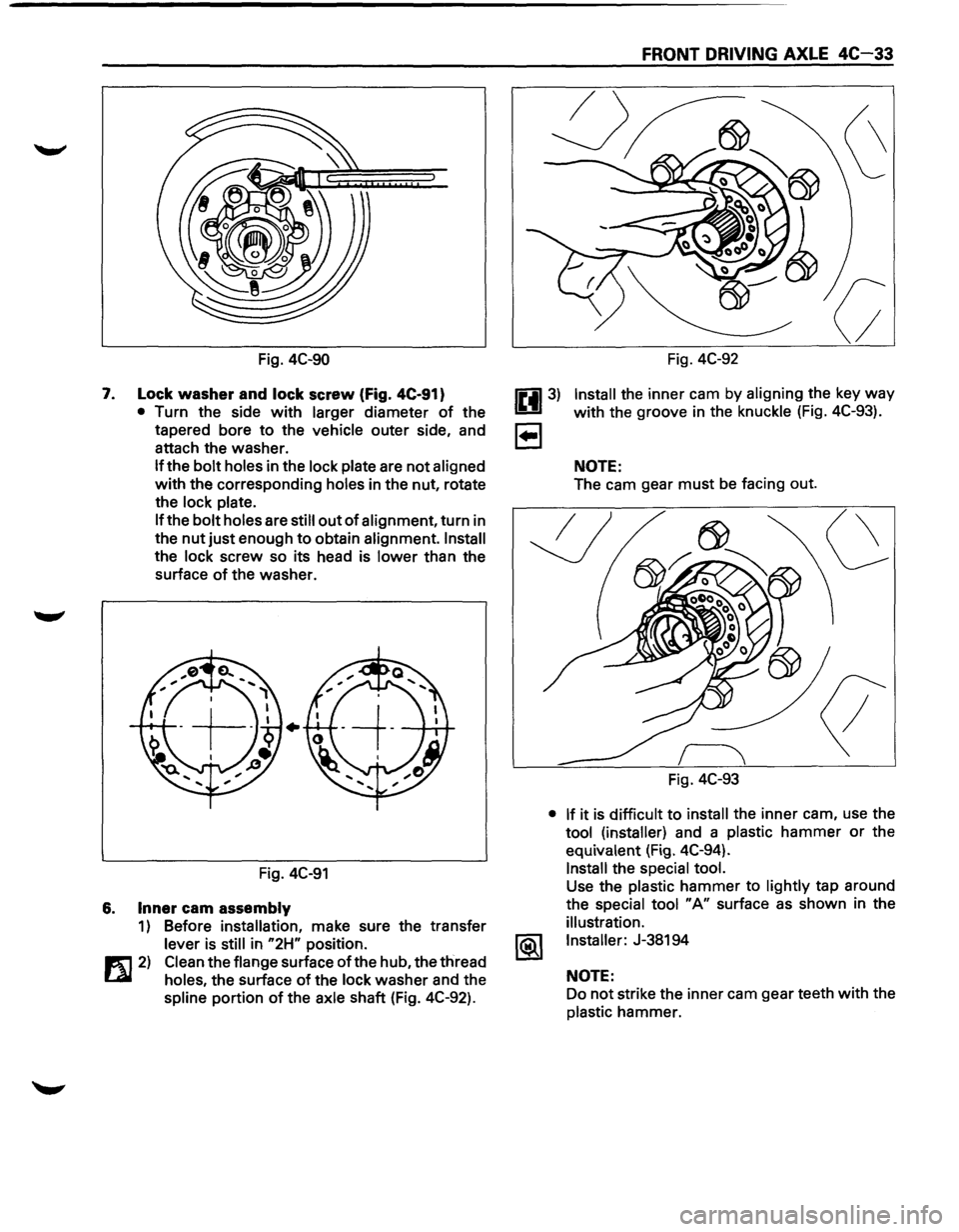
7.
Fig. 4C-90
Lock washer and lock screw (Fig. 4C-91}
• Turn the side with larger diameter of the
tapered bore
to the vehicle outer side, and
attach the washer.
If the bolt holes in the lock plate are not aligned
with the corresponding holes in the nut, rotate
the
lock plate.
If
the bolt holes are still out of alignment, turn in
the
nut just enough to obtain alignment. Install
the lock screw so its head is lower than the
surface
of the washer .
•
Fig. 4C-91
6. Inner cam assembly
1) Before installation, make sure the transfer
lever is still in "2H" position.
1!1::1 2) Clean the flange surface of the hub, the thread
Lil holes, the surface of the lock washer and the
spline portion of the axle shaft (Fig. 4C-92).
FRONT DRIVING AXLE 4C-33
Fig. 4C-92
Install the inner cam by aligning the key way
with the groove in the knuckle (Fig. 4C-93).
NOTE:
The cam gear must be facing out.
Fig. 4C-93
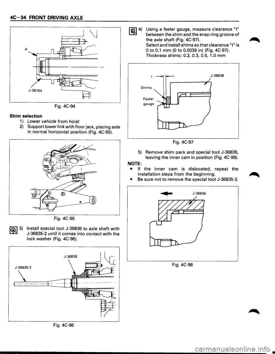
• If it is difficult to install the inner cam, use the
tool (installer) and a plastic hammer or the
equivalent (Fig. 4C-94).
Install the special tool.
Use the plastic hammer to lightly tap around
the
special tool "A" surface as shown in the
illustration.
Installer:
J-38194
NOTE:
Do not strike the inner cam gear teeth with the
plastic hammer.
Page 312 of 1928
4C-34 FRONT DRIVING AXLE
\j
A
J-38194
IFn
Fig. 4C-94
Shim selection
1) Lower vehicle from hoist
2) Support lower link with floor jack, placing axle
in normal horizontal position (Fig. 4C-95).
~ 3)
Fig. 4C-95
Install special tool J-36836 to axle shaft with
J-36835-2 until it comes into contact with the
lock washer (Fig. 4C-96).
J-36835-2
Fig. 4C-96
~4) Using a feeler gauge, measure clearance "t"
between the shim and the snap ring groove of
the axle shaft (Fig. 4C-97).
Select and
install shims so that clearance "t" is
0 to 0.1 mm (0 to 0.0039 in) (Fig. 4C-97).
Thickness shims; 0.2, 0.3, 0.5, 1.0
mm
J-36836
Fig. 4C-97
5) Remove shim pack and special tool J-36836,
leaving the inner cam in position (Fig. 4C-99).
NOTE:
• If the inner cam is dislocated, repeat the
installation steps from the beginning.
• Be sure not to remove the special tool J-36835-2.
J-36836
Fig. 4C-98
Page 313 of 1928
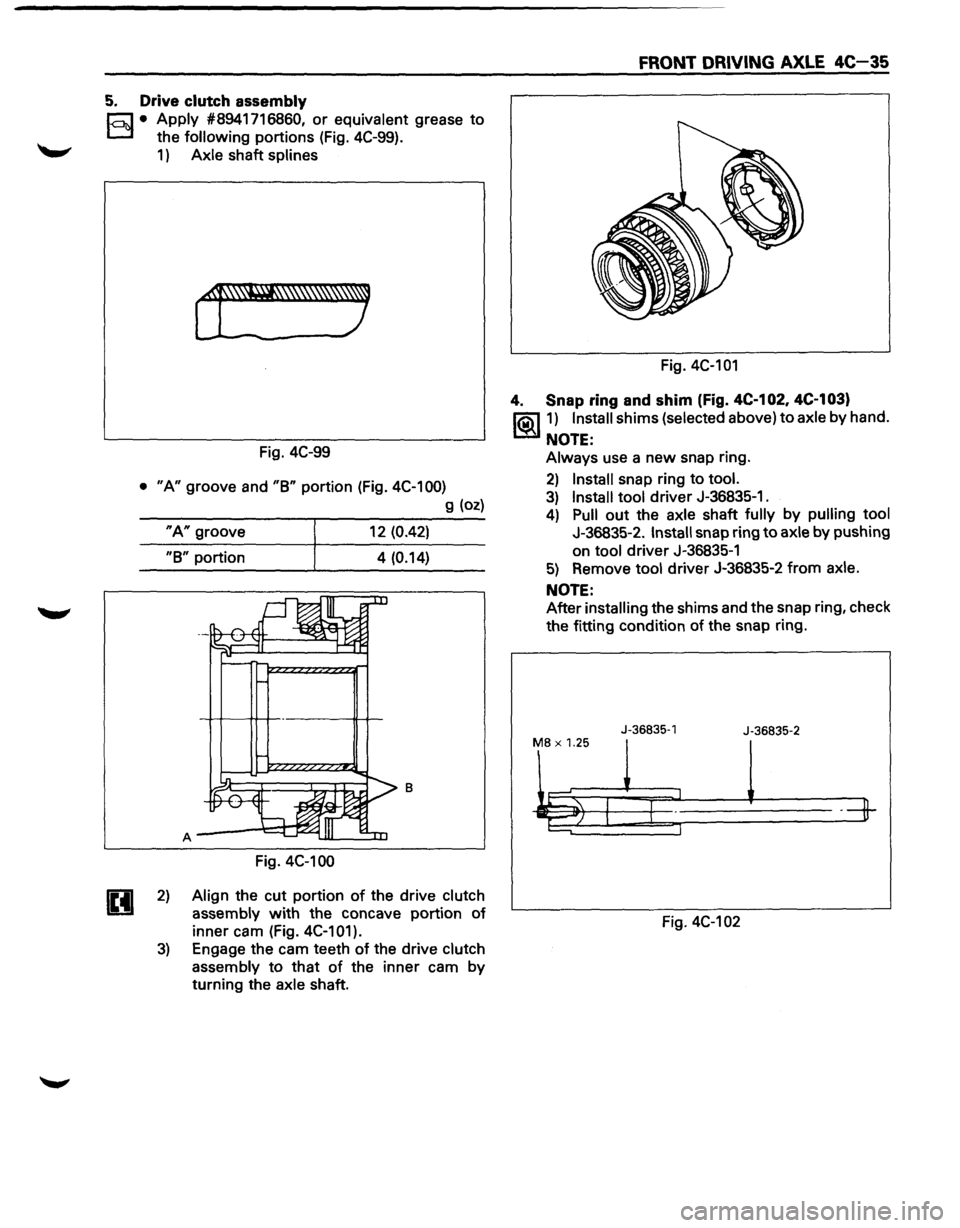
5. Drive clutch assembly
E3 • Apply #8941716860, or equivalent grease to
the following portions (Fig. 4C-99).
1) Axle shaft splines
Fig. 4C-99
• "A" groove and "B" portion (Fig. 4C-100)
g (oz)
"A" groove 12 (0.42)
"B" portion 4 (0.14)
8
Fig. 4C-100
2) Align the cut portion of the drive clutch
assembly with the concave portion of
inner cam (Fig. 4C-101).
3) Engage the cam teeth of the drive clutch
assembly to that of the inner cam by
turning the
axle shaft.
FRONT DRIVING AXLE 4C-35
Fig. 4C-101
4. Snap ring and shim (Fig. 4C-1 02, 4C·1 03)
1®..11) Install shims (selected above) to axle by hand.
NOTE:
Always use a new snap ring.
2) Install snap ring to tool.
3) Install tool driver J-36835-1.
4) Pull out the axle shaft fully by pulling tool
J-36835-2. Install snap ring to axle by pushing
on
tool driver J-36835-1
5) Remove tool driver J-36835-2 from axle.
NOTE:
After installing the shims and the snap ring, check
the fitting condition of the snap ring.
J-36835-1
J-36835-2
MB X 1.25
Fig. 4C-102
Page 314 of 1928
4C-36 FRONT DRIVING AXLE
Fig. 4C-103
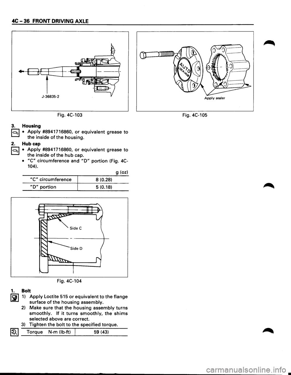
3. Housing
l<:::~t>l • Apply #8941716860, or equivalent grease to
the inside of the housing.
2. Hub cap
l<:::~t>l • Apply #8941716860, or equivalent grease to
the inside of the hub cap.
• "C" circumference and "D" portion (Fig. 4C-
104).
g (oz)
"C" circumference
8 (0.28)
"D" portion 5 (0.18)
Fig. 4C-104
1. Bolt
l!i!l 1) Apply Loctite 515 or equivalent to the flange
surface of the housing assembly.
2) Make sure that the housing assembly turns
smoothly. If it turns smoothly, the shims
selected above are correct.
3) Tighten the bolt to the specified torque.
~~~ Torque N·m (lb.ft) J 59 (43)
Apply sealer
Fig. 4C-105
Page 315 of 1928
FRONT DRIVING AXLE 4C-37
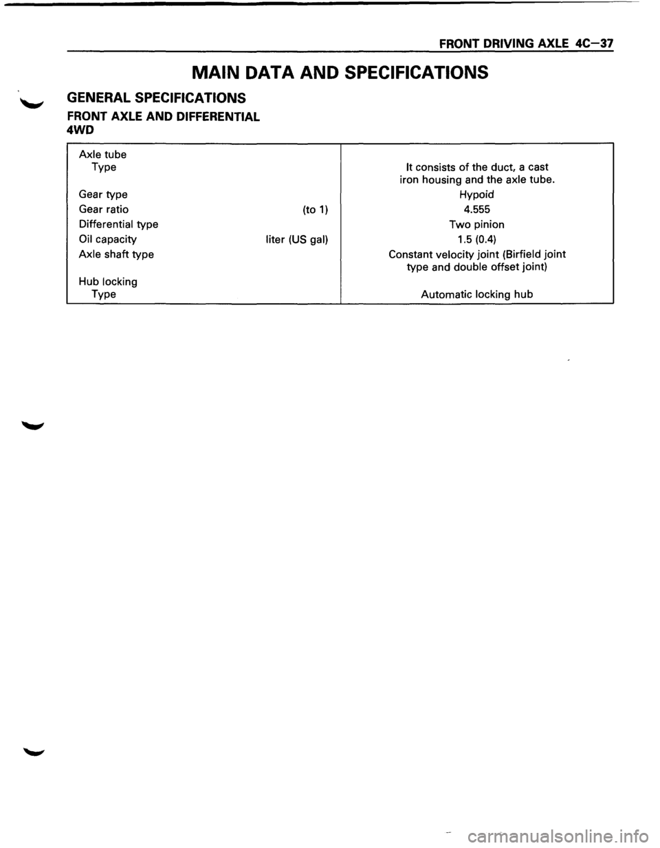
MAIN DATA AND SPECIFICATIONS
GENERAL SPECIFICATIONS
FRONT AXLE AND DIFFERENTIAL
4WD
Axle tube
Type
Gear type
Gear ratio
Differential type
Oil capacity
Axle shaft type
Hub locking
Type (to
1)
liter (US gal)
It consists of the
duct, a cast
iron housing and the axle tube.
Hypoid
4.555
Two pinion
1.5 (0.4)
Constant velocity joint (Birfield joint
type and double offset joint)
Automatic locking
hub
Page 316 of 1928
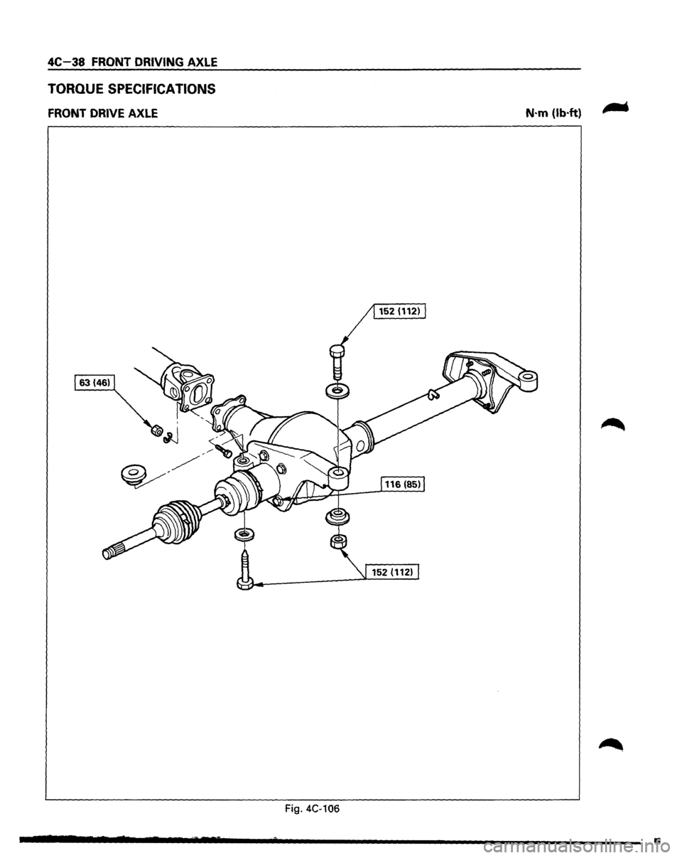
4C-38 FRONT DRIVING AXLE
TORQUE SPECIFICATIONS
FRONT DRIVE AXLE
Fig. 4C-106
N·m (lb·ft)
•
Page 317 of 1928
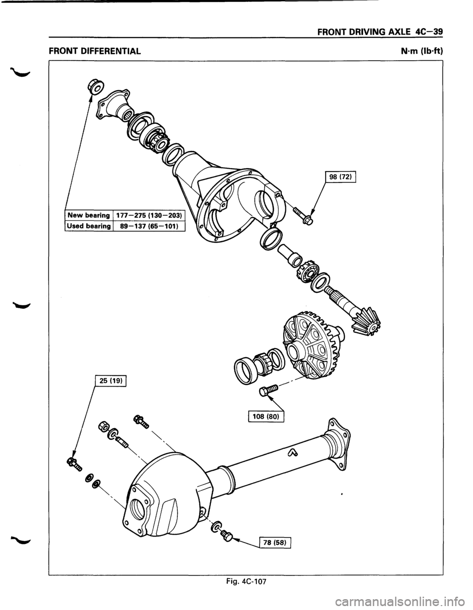
FRONT DIFFERENTIAL
New bearing 177-275 (130-203)
Used bearing 89-137 (65-101)
FRONT DRIVING AXLE 4C-39
N·m (lb·ft}
Fig. 4C-107
Page 318 of 1928
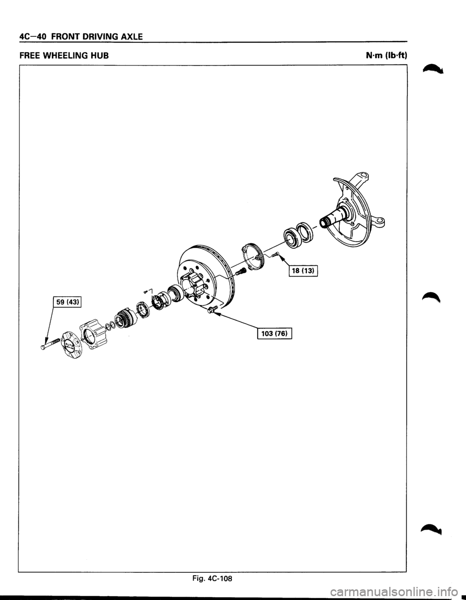
4C-40 FR _ __;,.=... • ONT DRIVING -=~~~~~A~X~L~E __ __
FREE WHEELING HUB ------------------N·m (lb·ft)
Fig. 4C-108
Page 319 of 1928
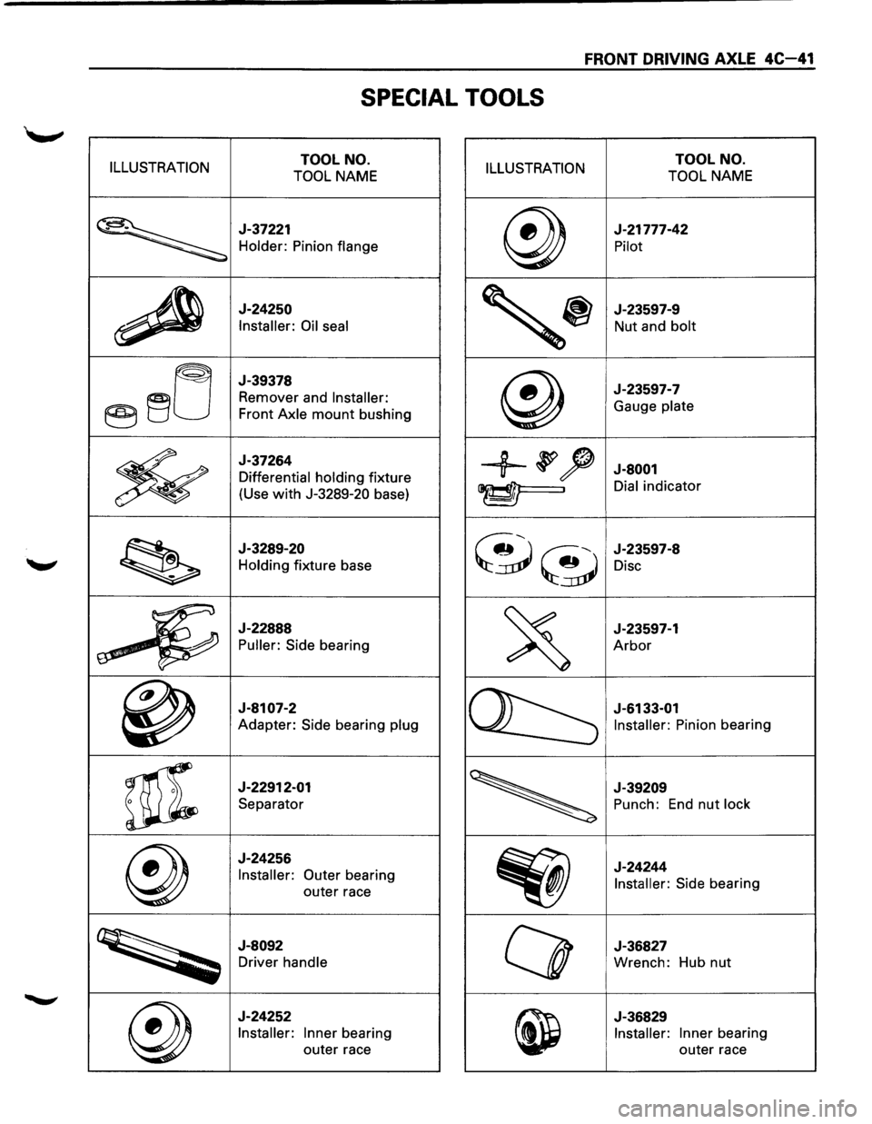
FRONT DRIVING AXLE 4C-41
SPECIAL TOOLS
ILLUSTRATION TOOL NO.
TOOL NAME ILLUSTRATION TOOL NO.
TOOL NAME
~
J-37221
Holder: Pinion flange @)
J-21777-42
Pilot
~
J-24250
Installer: Oil seal
'~
J-23597-9
Nut and bolt
@~lj
J-39378
Remover and Installer:
Front Axle mount bushing @
J-23597-7
Gauge plate
*
J-37264
Differential holding fixture
(Use
with J-3289-20 base)
+~? J-8001
~. Dial indicator
~
J-3289-20
Holding fixture base ~~
J-23597-8
Disc
"'"~
t>'"""_j~
J-22888
Puller: Side bearing
~
J-23597-1
Arbor
~
J-8107-2
Adapter: Side bearing plug
~
J-6133-01
Installer: Pinion bearing
~
J-22912-01
Separator
~
J-39209
Punch: End nut lock
@
J-24256
Installer:
Outer bearing
outer race
Eiij)
J-24244
Installer: Side bearing
~
J-8092
Driver handle Q
J-36827
Wrench: Hub nut
@)
J-24252
Installer: Inner bearing
outer race
~
J-36829
Installer: Inner bearing
outer race
Page 320 of 1928
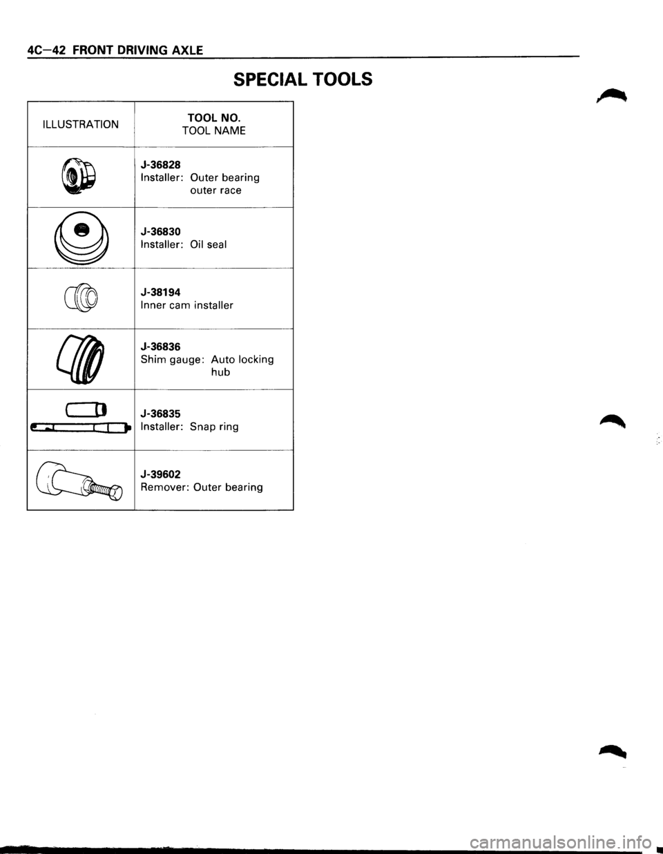
4C-42 FRONT DRIVING AXLE
SPECIAL TOOLS
ILLUSTRATION TOOL NO.
TOOL NAME
~
J-36828
Installer:
Outer bearing
outer race
@
J-36830
Installer:
Oil seal
C®
J-38194
Inner cam installer
{{(I
J-36836
Shim gauge: Auto locking
hub
( [I J-36835
t! aJ I I It Installer: Snap ring
~
J-39602
Remover:
Outer bearing