ignition ISUZU TROOPER 1995 Workshop Manual
[x] Cancel search | Manufacturer: ISUZU, Model Year: 1995, Model line: TROOPER, Model: ISUZU TROOPER 1995Pages: 1928
Page 1715 of 1928
Supplemental, Restraint System 9J-91
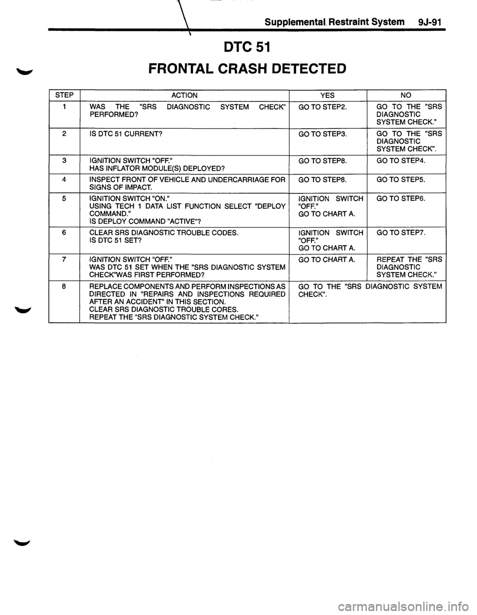
DTC51
FRONTAL CRASH DETECTED
STEP
ACTION YES NO
1 WAS THE "SRS
DIAGNOSTIC
SYSTEM CHECK" GOTOSTEP2. GO TO THE "SRS
PERFORMED? DIAGNOSTIC
SYSTEM CHECK."
2 IS DTC 51 CURRENT? GOTOSTEP3. GO TO THE "SRS
DIAGNOSTIC
SYSTEM CHECK".
3 IGNITION SWITCH "OFF." GOTOSTEP8. GOTOSTEP4.
HAS INFLATOR MODULE(S) DEPLOYED?
4
INSPECT FRONT OF VEHICLE AND UNDERCARRIAGE FOR GOTO STEPS. GOTO STEP5.
SIGNS OF IMPACT.
5 IGNITION SWITCH "ON."
IGNITION SWITCH GOTOSTEP6.
USING TECH 1 DATA LIST FUNCTION SELECT "DEPLOY
"OFF."
COMMAND." GO TO CHART A. IS DEPLOY COMMAND "ACTIVE"?
6 CLEAR SRS DIAGNOSTIC TROUBLE CODES. IGNITION SWITCH GOTOSTEP7. IS DTC 51 SET?
"OFF."
GO TO
CHART A.
7 IGNITION SWITCH "OFF."
GO TO CHART A. REPEAT THE "SRS
WAS
DTC 51 SET WHEN THE "SRS DIAGNOSTIC SYSTEM DIAGNOSTIC
CHECK"WAS FIRST PERFORMED? SYSTEM CHECK."
8
REPLACE COMPONENTS AND PERFORM INSPECTIONS AS GO TO THE "SRS DIAGNOSTIC SYSTEM
DIRECTED IN "REPAIRS AND INSPECTIONS REQUIRED
CHECK". AFTER AN ACCIDENT' IN THIS SECTION.
CLEAR SRS DIAGNOSTIC TROUBLE CORES. REPEAT THE "SRS DIAGNOSTIC SYSTEM CHECK."
Page 1716 of 1928
9J-92 Supplemental Restraint System
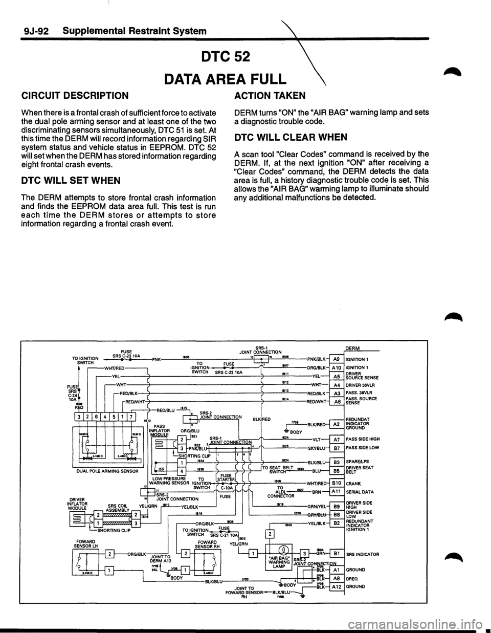
DTC52
CIRCUIT DESCRIPTION
DATA AREA FULL
ACTION TAKEN
When there is a frontal crash of sufficient force to activate
the dual pole arming sensor and at least one of the two
discriminating sensors simultaneously,
DTC 51 is set. At
this time the DERM
will record information regarding SIR
system status and vehicle status in EEPROM. DTC 52
will set when the DERM has stored information regarding
eight frontal crash events.
DTC WILL SET WHEN
The DERM attempts to store frontal crash information
and finds the
EEPROM data area full. This test is run
each time the DERM stores or attempts to store
information regarding a frontal crash event. DERM
turns
"ON" the "AIR BAG" warning lamp and sets
a diagnostic trouble code.
DTC WILL CLEAR WHEN
A scan tool "Clear Codes" command is received by the
DERM.
If, at the next ignition "ON" after receiving a
"Clear Codes" command, the DERM detects the data
area is
full, a history diagnostic trouble code is set. This
allows the "AIR BAG" warming lamp to illuminate should
any additional malfunctions be detected.
SRS·1 FUSE JOINT CONNECTION TO IGNITION SWITCH
FUSE! SRS C·2' 10A 1101 R D
--~SR~S~C~·23~1~0A~-IPNK----~~~~~------------_sn~~»~~~~·~~---l IGJ;~ON __ __.:FU:;:Si-E ____ _.fr;:--___ 1!!!107!!...-___ SWITCH SAS C·22 1 OA
FUSE STARTER 1801
Al~L • 1127 CONNECTOR 1111
1!120
IGNITION1
IGNITION1
DRIVER SOURCE SENSE DRIVER 36VLR PASS. 3SVLR PASS. SOURCE SENSE
REDUNDAT INDICATOR
GROUND
PASS SIDE HIGH
PASS SIDE LOW
SPARQPS DRIVER SEAT BELT
CRANK
SERIAL
DATA
DRIVER SIDE HIGH DRIVER SIDE LOW REDUNDANT INDICATOR
IGNITION 1
SRS INDICATOR
•
Page 1718 of 1928
9J-94 Supplemental Restraint System
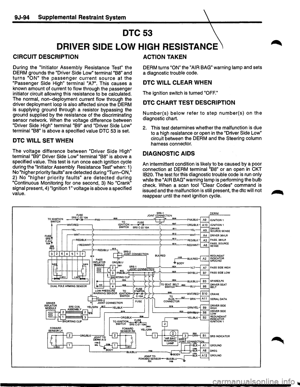
DTC53
DRIVER SIDE LOW HIGH RESISTANCE
CIRCUIT DESCRIPTION
During the "Initiator Assembly Resistance Test" the
DERM grounds the "Driver Side
Low" terminal "B8" and
turns "ON" the passenger current source at the
"Passenger Side High" terminal "A7". This causes a
known amount of current to
flow through the passenger
initiator circuit
allowing this resistance to be calculated.
The normal, non-deployment current flow through the
driver
deployment loop is also affected since the DERM
is
supplying ground through a resistor bypassing the
ground
supplied by the resistance of the discriminating
sensor network. When the
voltage difference between
"Driver Side High" terminal "B9" and "Driver Side Low"
terminal "B8" is above a specified value DTC 53 is set.
DTC WILL SET WHEN
The voltage difference between "Driver Side High"
terminal "B9" Driver Side Low" terminal "B8" is above a
specified
value. This test
is run once each ignition
cycle
during the "Initiator Assembly Resistance Test" when: 1)
No "higher priority
faults" are detected during "Turn-O.N,"
2) No "higher priority faults" are detected dunng
"Continuous Monitoring for one second, 3) No "Crank"
signal
present, 4) "Ignition 1" voltage is above a specified
value.
ACTION TAKEN
DERM turns "ON" the "AIR BAG" warning lamp and sets
a diagnostic
trouble code.
DTC WILL CLEAR WHEN
The ignition switch is turned "OFF."
DTC CHART TEST DESCRIPTION
Number(s) below refer to step number(s) on the
diagnostic chart.
2. This test determines whether the malfunction is due
to a high resistance or open
in the "Driver Side Low"
circuit between the DERM and the Steering
column
harness connector.
DIAGNOSTIC AIDS
An intermittent condition is likely to be caused by a poor
connection at DERM
terminal "B8" or an open in CKT
IB20.
The test for this diagnostic trouble code is run only
while
the "AIR BAG" warning lamp is performing the bulb
check. When a scan tool "Clear Codes" command is
issued and the
malfunction is still present, the dtc will not
reappear
until the next ignition cycle.
iYOS BLK/RE
.rBODY t824 VLT IB21J
DRIVER 36VLR PASS. 38VLR PASS. SOURCE SENSE
PASS SIDE HIGH
PASS SIDE LOW
l---....!E:L_-+--4+j-+-___..!!IB3~4--BLK/BLU
~-'!W.-4---4-~----'TO ~iJELT '"*' BLU
SERIAL DATA
DRIVER SIDE HIGH DRIVER SIDE LOW REDUNDANT INDICATOR IGNITION 1
SRS INDICATOR
Page 1719 of 1928
Supplemental Restraint System 9J-95
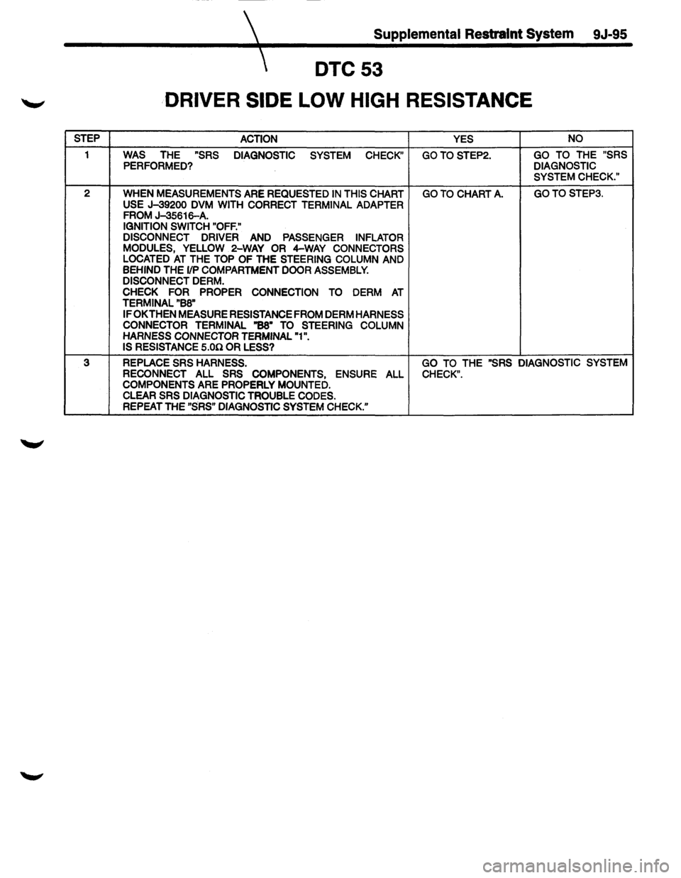
DTC53
DRIVER SIDE LOW HIGH RESISTANCE
STEP
ACTION YES
NO
1 WAS THE "SRS
DIAGNOSTIC SYSTEM CHECK" GOTOSTEP2. GO TO THE "SRS PERFORMED? DIAGNOSTIC
SYSTEM CHECK."
2
WHEN MEASUREMENTS ARE REQUESTED IN THIS CHART GO TO CHART A. GOTOSTEP3.
USE J-39200 DVM WITH CORRECT TERMINAL ADAPTER FROM J-35616-A. IGNITION SWITCH "OFF."
DISCONNECT DRIVER
AND PASSENGER INFLATOR
MODULES, YELLOW 2-WAY OR 4-WAY CONNECTORS
LOCATED AT THE TOP OF THE STEERING COLUMN AND
BEHIND THE 1/P COMPARTMENT DOOR ASSEMBLY.
DISCONNECT DERM.
CHECK FOR PROPER CONNECTION TO DERM AT TERMINAL "BB"
IF OK THEN MEASURE RESISTANCE FROM DERM HARNESS
CONNECTOR TERMINAL "BS• TO STEERING COLUMN
HARNESS CONNECTOR TERMINAL "1".
IS RESISTANCE
S.On OR LESS?
3 REPLACE SRS HARNESS. GO TO THE "SRS DIAGNOSTIC SYSTEM
RECONNECT
ALL SRS COMPONENTS, ENSURE ALL CHECK".
COMPONENTS ARE PROPERLY MOUNTED.
CLEAR SRS DIAGNOSTIC TROUBLE CODES.
REPEAT THE "SRS" DIAGNOSTIC SYSTEM CHECK."
Page 1720 of 1928
9J-96 Supplemental Restraint System
DTC54
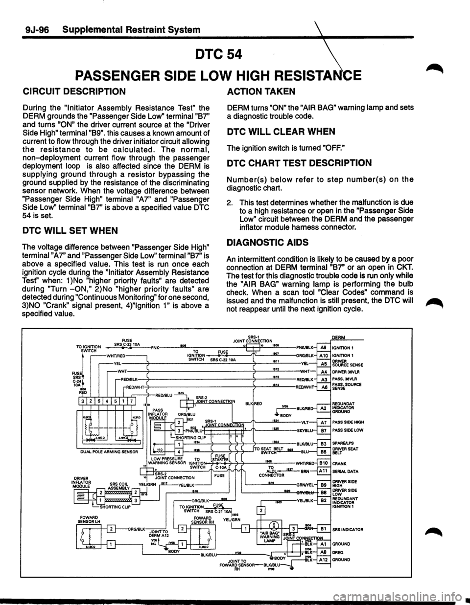
PASSENGER SIDE LOW HIGH RESISTA E
CIRCUIT DESCRIPTION
During the "Initiator Assembly Resistance Test" the
DERM grounds the "Passenger Side Low"
terminal "B7''
and turns
"ON" the driver current source at the "Driver
Side High" terminal "B9". this causes a known amount of
current to
flow through the driver initiator circuit allowing
the resistance to be calculated. The normal,
non-deployment current flow through the passenger
deployment loop is also affected since the DERM is
supplying ground through a resistor bypassing the
ground
supplied by the resistance of the discriminating
sensor network. When the
voltage difference between
"Passenger Side
High" terminal "A7" and "Passenger
Side Low''
terminal "B7" is above a specified value DTC
54 is set.
DTC WILL SET WHEN
The voltage difference between "Passenger Side High"
terminal "A7"
and "Passenger Side Low" terminal "B7" is
above a specified
value. This test is run once each
ignition
cycle during the "Initiator Assembly Resistance
Test" when:
1 )No "higher priority faults" are detected
during
"Turn -ON," 2)No "higher priority faults" are
detected during
"Continuous Monitoring" for one second,
3)NO "Crank" signal present, 4)"1gnition 1" is above a
specified
value.
ACTION TAKEN
DERM turns "ON" the "AIR BAG" warning lamp and sets
a diagnostic
trouble code.
DTC WILL CLEAR WHEN
The ignition switch is turned "OFF."
DTC CHART TEST DESCRIPTION
Number(s) below refer to step number(s) on the
diagnostic chart.
2. This test determines whether the malfunction is due
to a high resistance or open in the "Passenger Side
Low" circuit between the DERM and the passenger
inflator module harness connector.
DIAGNOSTIC AIDS
An intermittent condition is likely to be caused by a poor
connection at DERM
terminal "B7" or an open in CKT.
The test for this diagnostic trouble code is run only while
the "AIR BAG" warning lamp is performing the bulb
check. When a scan tool "Clear Codes" command is
issued and the
malfunction is still present, the DTC will ~
not reappear until the next ignition cycle.
SRS-1 JOINT CONNECTION 1105 1 10 TO FUSE IGNITION SWITCH SRS C-22 10A
PASS SIDE HIGH
PASS SIDE LOW
SERIAL
DATA
SRS INDICA TOR
•
Page 1721 of 1928
Supplemental Restraint System 9J-97
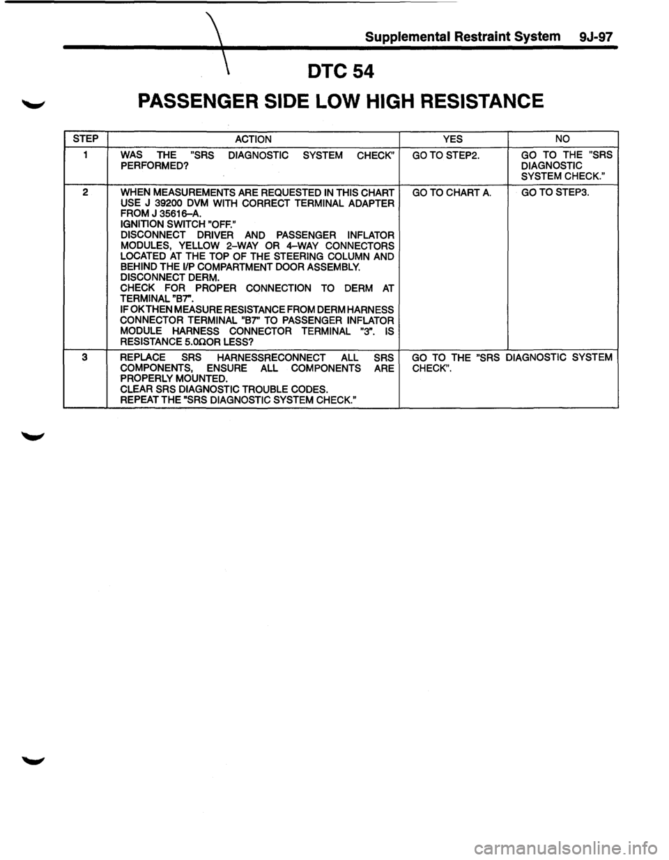
DTC54
PASSENGER SIDE LOW HIGH RESISTANCE
STEP
ACTION YES NO
1 WAS THE "SRS
DIAGNOSTIC
SYSTEM CHECK" GOTOSTEP2. GO TO THE "SRS PERFORMED? DIAGNOSTIC
SYSTEM CHECK."
2
WHEN MEASUREMENTS ARE REQUESTED IN THIS CHART GO TO CHART A. GOTOSTEP3.
USE J 39200 DVM WITH CORRECT TERMINAL ADAPTER FROM J 35616-A. IGNITION SWITCH "OFF."
DISCONNECT DRIVER
AND PASSENGER INFLATOR
MODULES, YELLOW 2-WAY OR 4-WAY CONNECTORS LOCATED AT THE TOP OF THE STEERING COLUMN AND BEHIND THE 1/P COMPARTMENT DOOR ASSEMBLY. DISCONNECT DERM. CHECK FOR
PROPER CONNECTION TO DERM AT TERMINAL "B7".
IF
OK THEN MEASURE RESISTANCE FROM DERM HARNESS
CONNECTOR TERMINAL "B7" TO PASSENGER INFLATOR
MODULE HARNESS CONNECTOR TERMINAL "3".
IS
RESISTANCE S.OilOR LESS?
3 REPLACE
SRS HARNESSRECONNECT ALL SRS GO TO THE "SRS DIAGNOSTIC SYSTEM
COMPONENTS,
ENSURE ALL COMPONENTS ARE CHECK". PROPERLY MOUNTED. CLEAR SRS DIAGNOSTIC TROUBLE CODES. REPEAT THE "SRS DIAGNOSTIC SYSTEM CHECK."
Page 1722 of 1928
9J-98 Supplemental Restraint System
DTC55
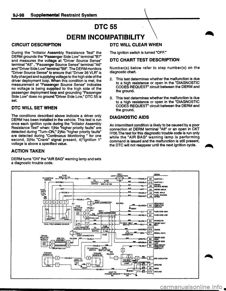
DERM INCOMPATIBILITY
CIRCUIT DESCRIPTION
During the "Initiator Assembly Resistance Test" the
DERM grounds the "Passenger
Side Low" terminal "B7"
and measures the voltage at "Driver Source Sense"
terminal "AS" , "Passenger Source Sense" terminal "A6"
and "Driver Side Low" terminai"B8". The DERM monitors
"Driver
Source Sense" to ensure that "Driver 36 VLR" is
fully charged and supplying voltage to the high side of the
driver deployment loop. When this condition is met, the
measurement at "Passenger
Source Sense" indicates
no voltage is being
supplied to the high side of the
passenger deployment loop and grounding "Passenger
Side Low'' does no ground "Driver Side Low," DTC 55 is
set.
DTC WILL SET WHEN
The conditions described above indicate a driver only
DERM has been installed in the vehicle. This test is run
once each ignition cycle during the
"Initiator Assembly
Resistance
Test" when: 1)No "higher priority faults" are
detected during
"Tum-oN," 2)No "higher priority faults"
are detected during "Continuous Monitoring
" for one
second, 3}No
"Crank" signal present, 4)"1gnition 1"
voltage is above a specified value.
ACTION TAKEN
DERM turns "ON" the "AIR BAG" warning lamp and sets
a diagnostic trouble code.
DTC WILL CLEAR WHEN
The ignition switch is turned "OFF."
DTC CHART TEST DESCRIPTION
Number(s) below refer to step number(s) on the
diagnostic chart.
2. This test determines whether the malfunction is due
to a high resistance
or open in the "DIAGNOSTIC
CODES REQUEST"
circuit between the DERM and
the ground.
3. This test determines whether the malfunction
is due
to a high resistance or open in the
"DIAGNOSTIC
CODES REQUEST"
circuit between the DERM and
the ground.
DIAGNOSTIC AIDS
An intermittent condition is likely to be caused by a poor
connection at DERM terminal
"AS" or an open in CKT
IY06.
The test for this diagnostic trouble code is run only
while the "AIR BAG" warning lamp is performing
command is issued and the malfunction is still present,
the
DTC will not reappear until the next ignition cycle. ~
PASS.:MVUI PASS. SOURCe SENSE
PASS SlOE HIGH PASS SlOE LOW
SERIAL DATA
•
Page 1723 of 1928
Supplemental Restraint System 9J-99
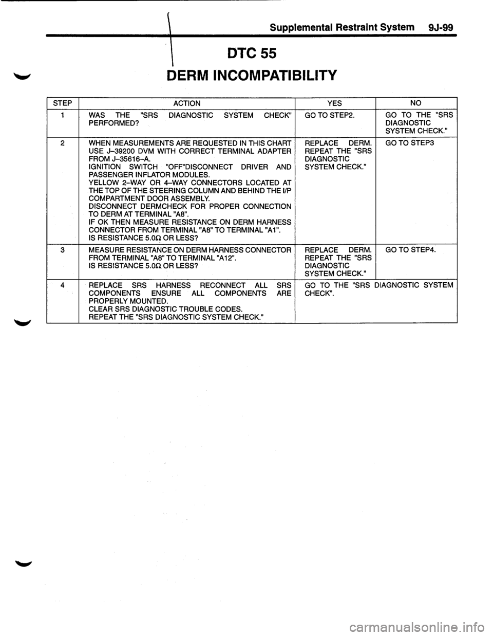
DTC55
DERM INCOMPATIBILITY
STEP ACTION YES NO
1
WAS THE "SRS DIAGNOSTIC SYSTEM CHECK'' GOTOSTEP2. GO TO THE "SRS
PERFORMED? DIAGNOSTIC
SYSTEM CHECK."
2 WHEN MEASUREMENTS ARE REQUESTED IN THIS CHART
REPLACE DERM. GOTO STEP3
USE
J-39200 DVM WITH CORRECT TERMINAL ADAPTER REPEAT THE "SRS
FROM J-35616-A. DIAGNOSTIC
IGNITION SWITCH
"OFF"DISCONNECT DRIVER AND SYSTEM CHECK."
PASSENGER INFLATOR MODULES.
YELLOW 2-WAY OR 4-WAY CONNECTORS LOCATED AT THE TOP OF THE STEERING COLUMN AND BEHIND THE liP COMPARTMENT DOOR ASSEMBLY. DISCONNECT DERMCHECK FOR PROPER CONNECTION
TO DERM AT TERMINAL "AS". IF OK THEN MEASURE RESISTANCE ON DERM HARNESS CONNECTOR FROM TERMINAL "AS" TO TERMINAL "A1".
IS RESISTANCE 5.00 OR LESS?
3 MEASURE RESISTANCE ON DERM HARNESS CONNECTOR REPLACE DERM. GOTO STEP4.
FROM TERMINAL "AS" TO TERMINAL "A 12".
REPEAT THE "SRS
IS RESISTANCE 5.00 OR LESS? DIAGNOSTIC
SYSTEM CHECK."
4 ·REPLACE SRS HARNESS RECONNECT ALL SRS GO TO THE "SRS DIAGNOSTIC SYSTEM
COMPONENTS
ENSURE ALL COMPONENTS ARE CHECK". PROPERLY MOUNTED.
CLEAR SRS DIAGNOSTIC TROUBLE CODES. REPEAT THE "SRS DIAGNOSTIC SYSTEM CHECK."
Page 1724 of 1928
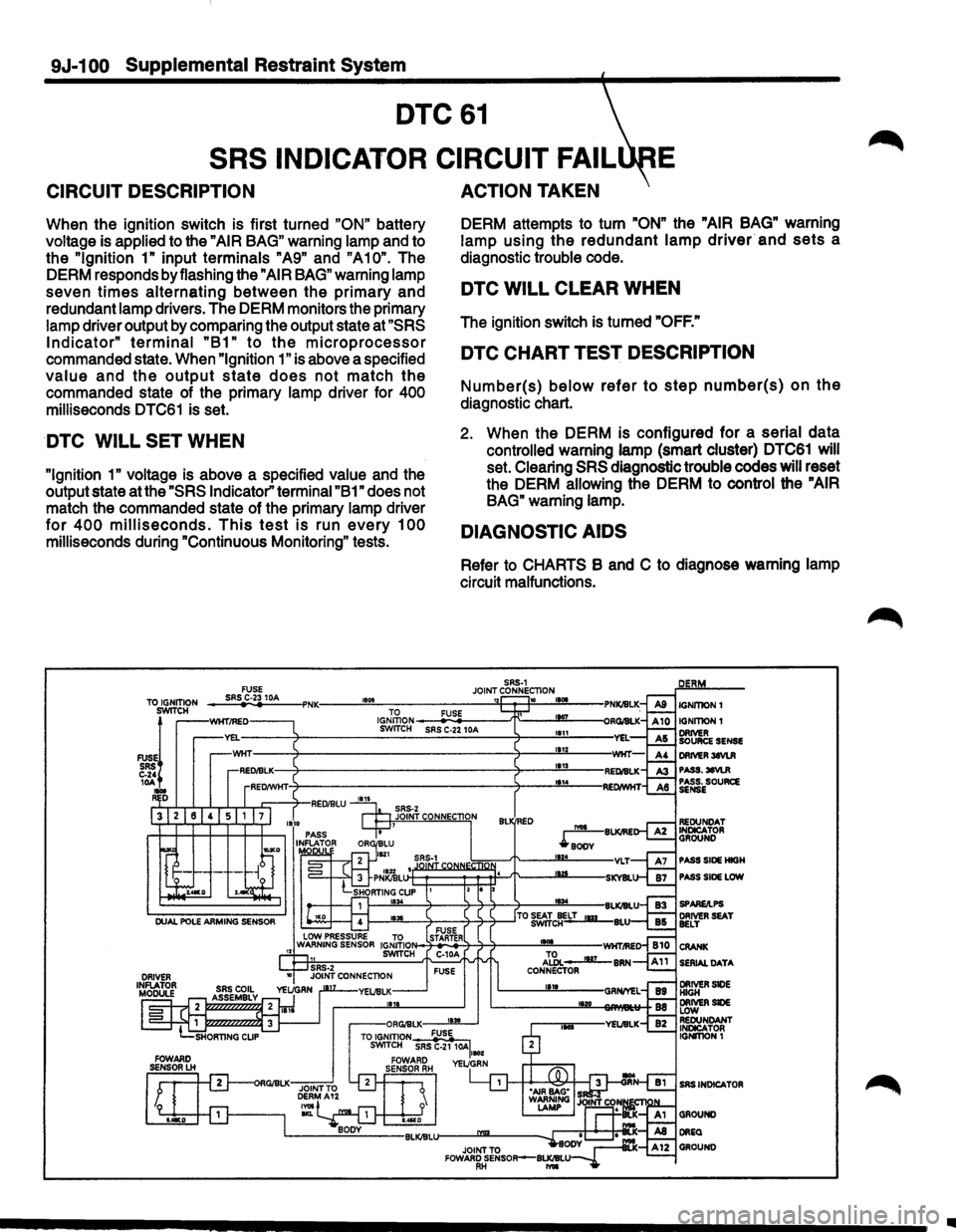
9J-1 00 Supplemental Restraint System
DTC61
SRS
INDICATOR CIRCUIT FAIL E
CIRCUIT DESCRIPTION
When the ignition switch is first turned "ON" battery
voltage is applied to the
"AIR BAG" warning lamp and to
the
"Ignition 1" input terminals "A9" and "A10". The
DERM responds by flashing the
"AIR BAG" warning lamp
seven
times alternating between the primary and
redundant lamp drivers. The DERM monitors the primary
lamp driver output by comparing the output state at
"SRS
Indicator" terminal "B1" to the microprocessor
commanded state. When "Ignition 1" is above a specified
value and the output state does not match the
commanded state of the primary lamp driver for 400
milliseconds DTC61 is set.
DTC WILL SET WHEN
"Ignition 1" voltage is above a specified value and the
output state at the
"SRS Indicator" terminal "B1" does not
match the commanded state of the primary lamp driver
for 400 milliseconds. This test is run every 100
milliseconds during "Continuous Monitoring" tests.
ACTION TAKEN
DERM attempts to turn "ON" the "AIR BAG" warning
lamp using
the redundant lamp driver and sets a
diagnostic trouble code.
DTC WILL CLEAR WHEN
The ignition switch is turned "OFF."
DTC CHART TEST DESCRIPTION
Number(s) below refer to step number(s) on the
diagnostic chart.
2. When the DERM is configured for a serial data
controlled warning lamp (smart cluster) DTC61 will
set. Clearing
SRS diagnostic trouble codes will reset
the DERM allowing the DERM to control the
"AIR
BAG"
warning lamp.
DIAGNOSTIC AIDS
Refer to CHARTS B and C to diagnose warning lamp
circuit malfunctions.
Ill
Page 1725 of 1928
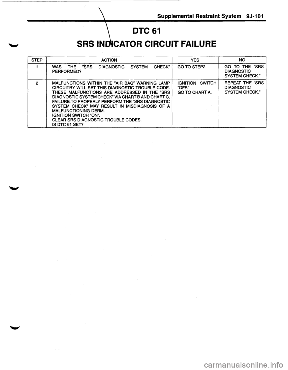
Supplemental Restraint System 9J-101
DTC61
CATOR CIRCUIT FAILURE
STEP ACTION YES NO
1 WAS THE "SRS
DIAGNOSTIC SYSTEM CHECK" GOTO STEP2. GO
TO THE "SRS
PERFORMED? DIAGNOSTIC
SYSTEM CHECK."
2 MALFUNCTIONS WITHIN THE "AIR BAG" WARNING LAMP IGNITION SWITCH REPEAT THE "SRS
CIRCUITRY WILL SET THIS DIAGNOSTIC TROUBLE CODE. "OFF." DIAGNOSTIC
THESE MALFUNCTIONS
ARE ADDRESSED IN THE "SRS GO TO CHART A. SYSTEM CHECK."
DIAGNOSTIC SYSTEM CHECK" VIA
CHART BAND CHART C. FAILURE TO PROPERLY PERFORM THE "SRS DIAGNOSTIC
SYSTEM CHECK'' MAY RESULT IN MISDIAGNOSIS OF A MALFUNCTIONING DERM.
IGNITION SWITCH "ON". CLEAR SRS DIAGNOSTIC TROUBLE CODES.
IS DTC 61 SET?