ignition ISUZU TROOPER 1995 Workshop Manual
[x] Cancel search | Manufacturer: ISUZU, Model Year: 1995, Model line: TROOPER, Model: ISUZU TROOPER 1995Pages: 1928
Page 1726 of 1928
9J-102 Supplemental Restraint System
DTC62
REDUNDANT SRS INDICATOR CIRCUIT FAIL RE
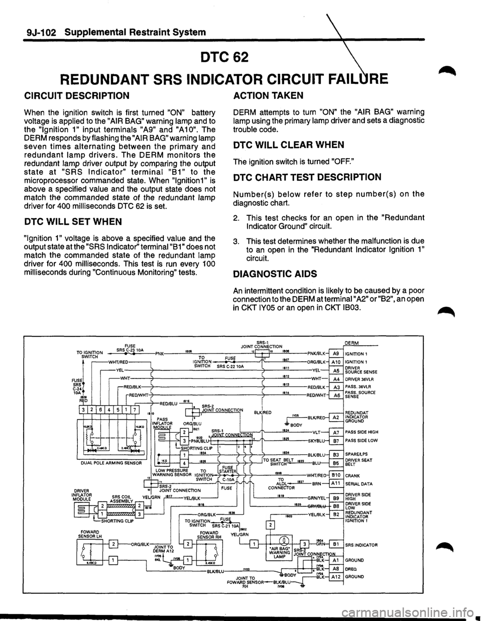
CIRCUIT DESCRIPTION
When the ignition switch is first turned "ON" battery
voltage is applied to the
"AIR BAG" warning lamp and to
the
"Ignition 1" input terminals "A9" and "A10". The
DERM responds by flashing the
"AIR BAG" warning lamp
seven
times alternating between the primary and
redundant lamp drivers. The DERM monitors the
redundant lamp driver output by comparing the output
state at "SRS Indicator" terminal "B1" to the
microprocessor commanded state. When
"lgnition1" is
above a specified value and the output state does not
match the commanded state of the redundant lamp
driver for
400 milliseconds DTC 62 is set.
DTC WILL SET WHEN
"Ignition 1" voltage is above a specified value and the
output state at the
"SRS Indicator'' terminal "B 1" does not
match the commanded state of the redundant lamp
driver for
400 milliseconds. This test is run every 100
milliseconds during "Continuous Monitoring" tests.
FUSE
ACTION TAKEN
DERM attempts to turn "ON" the "AIR BAG" warning
lamp using the primary lamp driver and sets a diagnostic
trouble code.
DTC WILL CLEAR WHEN
The ignition switch is turned "OFF."
DTC CHART TEST DESCRIPTION
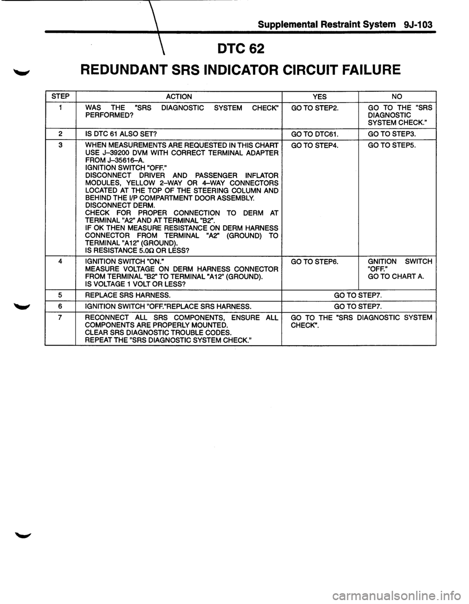
Number(s) below refer to step number(s) on the
diagnostic chart.
2. This test checks for an open in the "Redundant
Indicator Ground"
circuit.
3. This test determines whether the malfunction is due
to
an open in the "Redundant Indicator Ignition 1"
circuit.
DIAGNOSTIC AIDS
An intermittent condition is likely to be caused by a poor
connection to the DERM at terminal
"A2" or "B2", an open
in
CKT IY05 or an open in CKT IB03.
SRS-1 JOINT CONNECTION ___ sR~SrC~·23~1_M ___ ,PNK:----~"~~------------~"~~~~18~~~--TO IGNITION SWITCH IGNITION 1
FUSE!
SRS C-24 lOA 1800 RED
WKT/RED IGJ~oN ---
PASS SIDE HIGH
PASS SIDE LOW
DRIVER SEAT BELT
CRANK
SERIAL DATA
DRIVER SIDE HIGH DRIVER SIDE LOW REDUNDANT INDICATOR
IGNITION 1
SRS INDICATOR
Page 1727 of 1928
Supplemental Restraint System 9J-103
DTC62
REDUNDANT SRS INDICATOR CIRCUIT FAILURE
STEP
ACTION YES NO
1 WAS THE "SRS
DIAGNOSTIC
SYSTEM CHECK'' GOTOSTEP2. GO TO THE "SRS PERFORMED? DIAGNOSTIC
SYSTEM CHECK."
2 IS DTC 61 ALSO SET? GOTO DTC61. GOTOSTEP3.
3
WHEN MEASUREMENTS ARE REQUESTED IN THIS CHART GOTOSTEP4. GOTOSTEP5.
USE J-39200 DVM WITH CORRECT TERMINAL ADAPTER FROM J-35616-A. IGNITION SWITCH "OFF."
DISCONNECT DRIVER
AND PASSENGER INFLATOR
MODULES, YELLOW 2-WAY OR 4-WAY CONNECTORS
LOCATED AT THE TOP OF THE STEERING COLUMN AND BEHIND THE 1/P COMPARTMENT DOOR ASSEMBLY.
DISCONNECT DERM. CHECK FOR PROPER CONNECTION
TO DERM AT TERMINAL "A2" AND AT TERMINAL "B2".
IF OK THEN MEASURE RESISTANCE ON DERM HARNESS
CONNECTOR FROM TERMINAL
"A2"
(GROUND) TO
TERMINAL "A 12" (GROUND). IS RESISTANCE 5.00 OR LESS?
4 IGNITION SWITCH "ON." GOTOSTEP6. GNITION SWITCH MEASURE
VOLTAGE ON DERM HARNESS CONNECTOR "OFF."
FROM TERMINAL "B2" TO TERMINAL "A12" (GROUND). GO TO CHART A.
IS VOLTAGE 1 VOLT OR LESS?
5 REPLACE SRS HARNESS. GOTOSTEP7.
6 IGNITION SWITCH "OFF."REPLACE SRS HARNESS. GOTOSTEP7.
7 RECONNECT ALL SRS COMPONENTS, ENSURE ALL GO TO THE "SRS DIAGNOSTIC SYSTEM
COMPONENTS ARE PROPERLY MOUNTED. CHECK".
CLEAR SRS DIAGNOSTIC TROUBLE CODES. REPEAT THE "SRS DIAGNOSTIC SYSTEM CHECK."
Page 1728 of 1928
9J-1 04 Supplemental Restraint System
DESCRIPTION
DTC 71 AND/OR 75
INTERNAL DERM FAULT CIRCUIT
ACTION TAKEN
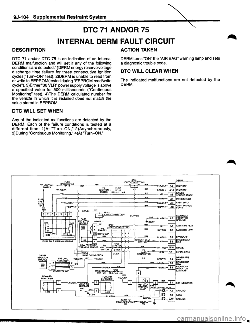
DTC 71 and/or DTC 75 is an indication of an internal
DERM malfunction and
will set if any of the following
conditions are detected:1 )DERM energy reserve voltage
discharge time failure for three consecutive ignition
cycles("Turn-ON" test), 2)DERM is unable to read from
or write to EEPROM(tested during
"EEPROM read/write
cycle"), 3)Either
"36 VLR" power supply voltage is above
a specified value for
500 milliseconds ("Continuous
Monitoring" test), 4)The DERM calculated number for
the vehicle
in which it is installed does not match the
value stored in EEPROM. DERM
turns
"ON" the "AIR BAG" warning lamp and sets
a diagnostic trouble code.
DTC WILL SET WHEN
Any of the indicated malfunctions are detected by the
DERM. Each of the failure conditions is tested at a
different time: 1 )At "Turn-ON," 2)Asynchronously,
3)During "Continuous Monitoring," 4)At
"Turn-ON."
DTC WILL CLEAR WHEN
The indicated malfunctions are not detected by the
DERM.
FUSE JOINT C~~N~CTION TO IGNITION
ru • .'jWITCH
SRS C-24 1~ , ... R D
--~SR~S~C~-~.1~~~-IPNK----~~·~~------------~~~w--~1-~---
>N-~~4---.::r---::r----___!!'B!!!!oa'-------WHT/REO
AL~L____mz._BRN CONNECTOR IB1t
1120
IGNITION 1 IGNITION 1 DRIVER SOURCE SENSE DRIVER 36VLR PASS.35VLR PASS. SOURCE SENSE
REDUNDAT INDICATOR GROUND
PASS SIDE HIGH
PASS SIDE LOW
SERIAL DATA
DRIVER SIDE HIGH DRIVER SIDE LOW REDUNDANT INDICATOR IGNITION1
SRS INDICATOR
•
Page 1730 of 1928
9J-106 Supplemental Restraint System
DTC81
DRIVER IGNITION DIODE OPEN
CIRCUIT DESCRIPTION
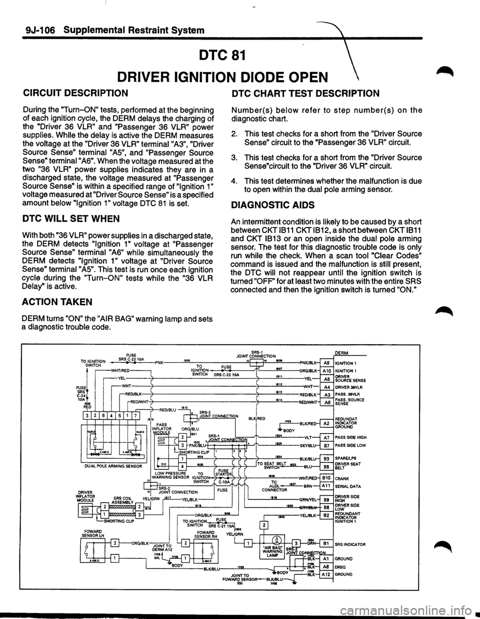
During the "Turn-ON" tests, performed at the beginning
of each ignition
cycle, the DERM delays the charging of
the "Driver
3S VLR" and "Passenger 3S VLR" power
supplies. While the delay is active the DERM measures
the
voltage at the "Driver 3S VLR" terminal "A3", "Driver
Source
Sense" terminal "AS", and "Passenger Source
Sense" terminal "AS". When the voltage measured at the
two
"3S VLR" power supplies indicates they are in a
discharged state, the
voltage measured at "Passenger
Source
Sense" is within a specified range of "Ignition 1"
voltage
measured at "Driver Source Sense" is a specified
amount
below "Ignition 1" voltage DTC 81 is set.
DTC WILL SET WHEN
With both "3S VLR" power supplies in a discharged state,
the DERM detects
"Ignition 1" voltage at "Passenger
Source
Sense" terminal "AS" while simultaneously the
DERM detects
"Ignition 1" voltage at "Driver Source
Sense" terminal "AS". This test is run once each ignition
cycle during the "Turn-ON" tests while the "3S VLR
Delay"
is active.
ACTION TAKEN
DERM turns "ON" the "AIR BAG" warning lamp and sets
a diagnostic
trouble code.
DTC CHART TEST DESCRIPTION
Number(s) below refer to step number(s) on the
diagnostic chart.
2. This test checks for a short from the "Driver Source
Sense" circuit to the "Passenger 3S VLR" circuit.
3. This test checks for a short from the "Driver Source
Sense"circuit to the "Driver
3S VLR" circuit.
4. This test determines whether the malfunction is due
to open within the
dual pole arming sensor.
DIAGNOSTIC AIDS
An intermittent condition is likely to be caused by a short
between
CKT 1811 CKTIB12, a short between CKT 1811
and CKT 1813 or an open inside the dual pole arming
sensor. The test for this diagnostic
trouble code is only
run while the check. When a scan tool "Clear Codes"
command is issued and the malfunction is still present,
the
DTC will not reappear until the ignition switch is
turned
"OFF" for at least two minutes with the entire SRS
connected and then the ignition switch is turned "ON."
SRS-1 FUSE JOINT CONNECTION TOS~~~:?N -_;:,;SR-"
IGNmON ~-=-------"T"---""'1107<----SWrTCH SRS C-22 10A 1111
1112 DRIVER 36VLR PASS.36VLR PASS. SOURCE SENSE
REOUNOAT INDICATOR GROUND
PASS SIDE HIGH
PASS SIDE LOW
SERIAL DATA
SRS INDICATOR
•
Page 1731 of 1928
Supplemental Restraint System 9J-1 07
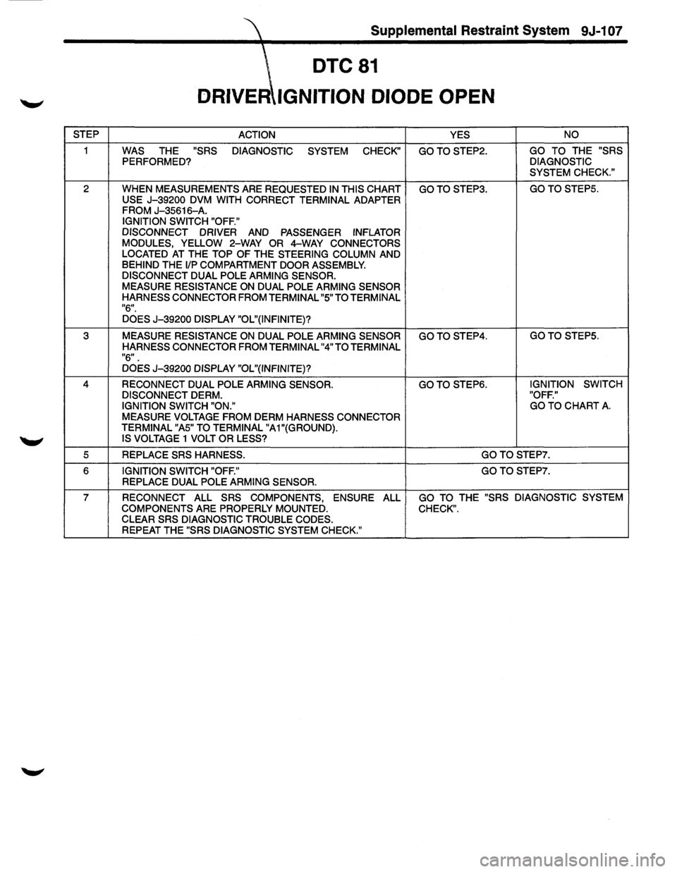
DTC81
DRIVER IGNITION DIODE OPEN
STEP
ACTION
YES NO
1 WAS THE "SRS
DIAGNOSTIC
SYSTEM CHECK" GOTOSTEP2. GO TO THE "SRS
PERFORMED? DIAGNOSTIC
SYSTEM CHECK."
2
WHEN MEASUREMENTS ARE REQUESTED IN THIS CHART GOTOSTEP3. GO TO STEPS.
USE
J-39200 DVM WITH CORRECT TERMINAL ADAPTER
FROM J-35616-A. IGNITION SWITCH "OFF."
DISCONNECT DRIVER
AND PASSENGER INFLATOR
MODULES, YELLOW 2-WAY OR 4-WAY CONNECTORS
LOCATED AT THE TOP OF THE STEERING COLUMN AND BEHIND THE 1/P COMPARTMENT DOOR ASSEMBLY.
DISCONNECT DUAL POLE ARMING SENSOR.
MEASURE RESISTANCE ON DUAL POLE ARMING SENSOR
HARNESS CONNECTOR FROM TERMINAL "5" TO TERMINAL
"6".
DOES J-39200 DISPLAY "OL"(INFINITE)?
3 MEASURE RESISTANCE ON DUAL POLE ARMING SENSOR GOTOSTEP4. GO TO STEPS.
HARNESS CONNECTOR FROM TERMINAL "4" TO TERMINAL
"6".
DOES J-39200 DISPLAY "OL"(INFINITE}?
4 RECONNECT DUAL POLE ARMING SENSOR. GOTOSTEP6. IGNITION SWITCH
DISCONNECT
DERM. "OFF."
IGNITION SWITCH "ON." GO
TO CHART A.
MEASURE VOLTAGE FROM DERM HARNESS CONNECTOR
TERMINAL "AS" TO TERMINAL "A1"(GROUND).
IS VOLTAGE 1 VOLT OR LESS?
5 REPLACE SRS HARNESS. GOTOSTEP7.
6 IGNITION SWITCH "OFF." GOTOSTEP7.
REPLACE DUAL POLE ARMING SENSOR.
7 RECONNECT ALL SRS COMPONENTS,
ENSURE ALL GO TO THE "SRS DIAGNOSTIC SYSTEM
COMPONENTS
ARE PROPERLY MOUNTED. CHECK". CLEAR SRS DIAGNOSTIC TROUBLE CODES.
REPEAT THE "SRS DIAGNOSTIC SYSTEM CHECK."
Page 1732 of 1928
9J-1 08 Supplemental Restraint System
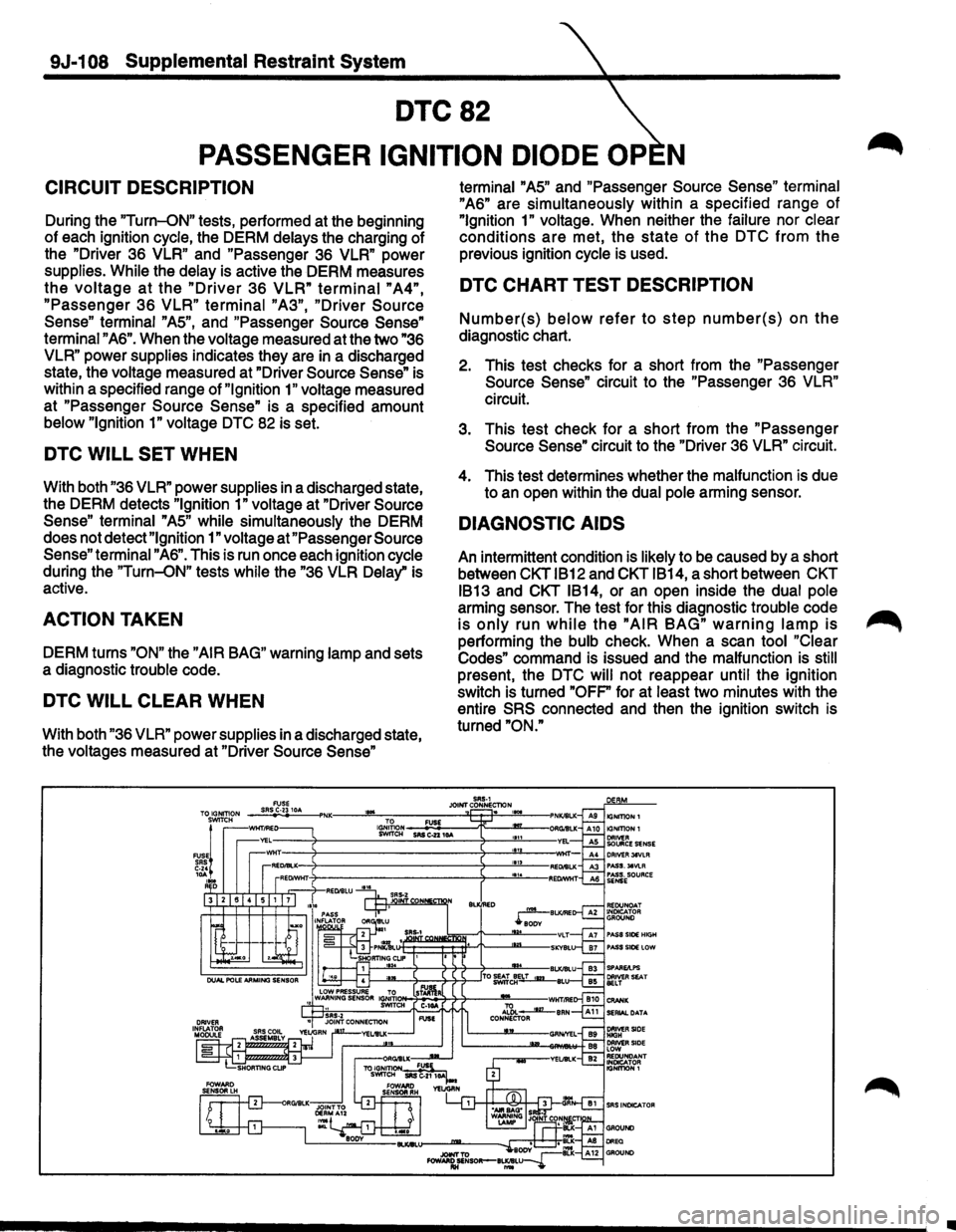
DTC82
PASSENGER IGNITION DIODE OP N
CIRCUIT DESCRIPTION
During the "Turn-ON" tests, performed at the beginning
of each ignition
cycle, the DERM delays the charging of
the "Driver 36
VLR" and "Passenger 36 VLR" power
supplies.
While the delay is active the DERM measures
the voltage at the "Driver 36 VLR" terminal "A4",
"Passenger 36 VLR" terminal "A3", "Driver Source
Sense"
terminal "AS", and "Passenger Source Sense"
terminal "A6". When the voltage measured at the two "36
VLR"
power supplies indicates they are in a discharged
state, the voltage measured at "Driver
Source Sense" is
within a specified range of
"Ignition 1" voltage measured
at "Passenger
Source Sense" is a specified amount
below "Ignition 1" voltage DTC 82 is set.
DTC WILL SET WHEN
With both "36 VLR" power supplies in a discharged state,
the DERM detects
"Ignition 1" voltage at "Driver Source
Sense" terminal
"AS" while simultaneously the DERM
does not detect
"Ignition 1" voltage at "Passenger Source
Sense"
terminal "A6". This is run once each ignition cycle
during the
"Turn-ON" tests while the "36 VLR Delay" is
active.
ACTION TAKEN
DERM turns "ON" the "AIR BAG" warning lamp and sets
a diagnostic trouble code.
DTC WILL CLEAR WHEN
With both "36 VLR" power supplies in a discharged state,
the voltages measured at "Driver
Source Sense"
'"'
terminal "AS" and "Passenger Source Sense" terminal
"A6" are simultaneously within a specified range of
"Ignition 1" voltage. When neither the failure nor clear
conditions are met, the state of the DTC from the
previous ignition cycle is used.
DTC CHART TEST DESCRIPTION
Number{s) below refer to step number{s) on the
diagnostic chart.
2. This test checks for a short from the "Passenger
Source Sense" circuit to the "Passenger 36 VLR"
circuit.
3. This test check for a short from the "Passenger
Source Sense" circuit to the "Driver 36 VLR" circuit.
4. This test determines whether the malfunction is due
to an open within the
dual pole arming sensor.
DIAGNOSTIC AIDS
An intermittent condition is likely to be caused by a short
between
CKT IB12 and CKT IB14, a short between CKT
IB13
and CKT IB14, or an open inside the dual pole
arming sensor. The test for this diagnostic trouble code
is only run while the "AIR BAG" warning lamp is
performing the bulb check. When a scan tool "Clear
Codes"
command is issued and the malfunction is still
present, the DTC will not reappear until the ignition
switch is turned
"OFP for at least two minutes with the
entire
SRS connected and then the ignition switch is
turned
"ON."
SRS-1 JOINT CONNEcnoN . lG,J;~ON _ _.::FU::OS£'---.-r:--m_-SWITCH SRS C..z2 10A
•
Page 1733 of 1928
Supplemental Restraint System 9J-1 09
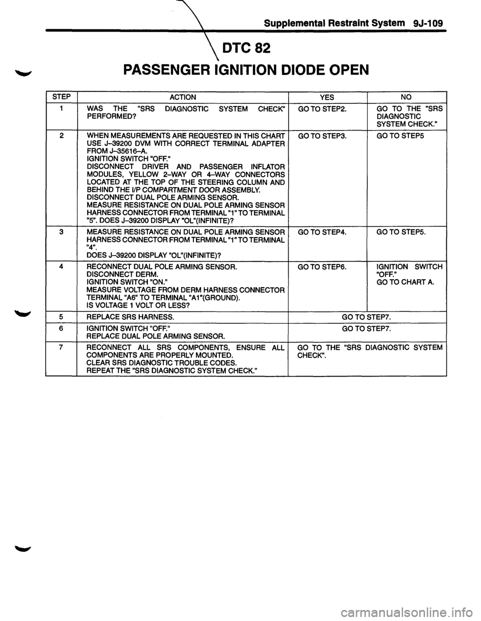
DTC82
PASSENGER IGNITION DIODE OPEN
STEP
ACTION YES NO
1 WAS THE "SRS
DIAGNOSTIC
SYSTEM
CHECK" GOTOSTEP2. GO TO THE "SRS PERFORMED? DIAGNOSTIC
SYSTEM CHECK."
2
WHEN MEASUREMENTS ARE REQUESTED IN THIS CHART GOTOSTEP3. GOTOSTEP5 USE J-39200 DVM WITH CORRECT TERMINAL ADAPTER
FROM J-35616-A. IGNITION SWITCH "OFF."
DISCONNECT DRIVER
AND PASSENGER INFLATOR
MODULES, YELLOW 2-WAY OR 4-WAY CONNECTORS
LOCATED AT THE TOP OF THE STEERING COLUMN AND BEHIND THE 1/P COMPARTMENT DOOR ASSEMBLY.
DISCONNECT DUAL POLE ARMING SENSOR.
MEASURE RESISTANCE ON DUAL POLE ARMING SENSOR
HARNESS CONNECTOR FROM TERMINAL "1" TO TERMINAL
"5". DOES J-39200 DISPLAY "OL"(INFINITE}?
3 MEASURE RESISTANCE ON DUAL POLE ARMING SENSOR GOTOSTEP4. GOTOSTEP5.
HARNESS CONNECTOR FROM TERMINAL "1" TO TERMINAL "4".
DOES J-39200 DISPLAY "OL"(INFINITE}?
4 RECONNECT DUAL POLE ARMING SENSOR. GOTOSTEP6. IGNITION SWITCH
DISCONNECT DERM. "OFF."
IGNITION SWITCH "ON." GO TO CHART A.
MEASURE VOLTAGE FROM DERM HARNESS CONNECTOR
TERMINAL "A6" TO TERMINAL "A1"(GROUND}.
IS VOLTAGE
1 VOLT OR LESS?
5 REPLACE SRS HARNESS. GOTOSTEP7.
6 IGNITION SWITCH "OFF." GOTOSTEP7. REPLACE DUAL POLE ARMING SENSOR.
7 RECONNECT ALL SRS COMPONENTS, ENSURE ALL GO TO THE "SRS DIAGNOSTIC SYSTEM
COMPONENTS ARE PROPERLY MOUNTED. CHECK".
CLEAR SRS DIAGNOSTIC TROUBLE CODES.
REPEAT THE "SRS DIAGNOSTIC SYSTEM CHECK."
Page 1734 of 1928
9J-110 Supplemental Restraint Syst~m
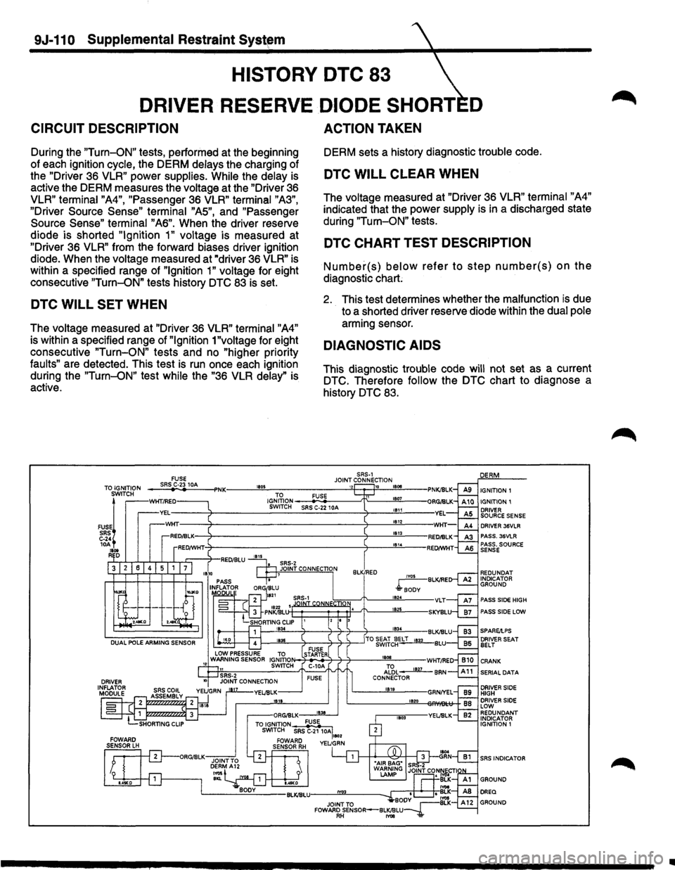
HISTORY DTC 83
DRIVER RESERVE DIODE SHORT D
CIRCUIT DESCRIPTION
During the "Turn-ON" tests, performed at the beginning
of each ignition cycle, the DERM delays the charging of
the "Driver 36
VLR" power supplies. While the delay is
active the DERM measures the voltage at the "Driver 36
VLR" terminal "A4", "Passenger 36 VLR" terminal "A3",
"Driver Source Sense" terminal "AS", and "Passenger
Source Sense" terminal "A6". When the driver reserve
diode is shorted
"Ignition 1" voltage is measured at
"Driver 36
VLR" from the forward biases driver ignition
diode. When the voltage measured at "driver 36
VLR" is
within a specified range of
"Ignition 1" voltage for eight
consecutive
"Turn-ON" tests history DTC 83 is set.
DTC WILL SET WHEN
The voltage measured at "Driver 36 VLR" terminal "A4"
is within a specified range of "Ignition 1"voltage for eight
consecutive
"Turn-ON" tests and no "higher priority
faults" are detected. This test is run once each ignition
during the
"Turn-ON" test while the "36 VLR delay" is
active.
a SRS·Z
ACTION TAKEN
DERM sets a history diagnostic trouble code.
DTC WILL CLEAR WHEN
The voltage measured at "Driver 36 VLR" terminal "A4"
indicated that the power supply is in a discharged state
during
"Turn-ON" tests.
DTC CHART TEST DESCRIPTION
Number(s) below refer to step number(s) on the
diagnostic chart;
2. This test determines whether the malfunction is due
to a shorted driver reserve diode within the dual pole
arming sensor.
DIAGNOSTIC AIDS
This diagnostic trouble code will not set as a current
DTC. Therefore
follow the DTC chart to diagnose a
history
DTC 83.
SRS-1 JOINT CONNECTION
IGNITION 1
IGNITION 1 DRIVER
SOURCE SENSE
DRIVER
36VLR PASS. 36VlR PASS. SOURCE
SENSE
JOINT CONNECTION
REDUNDAT INDICATOR GROUND IY05 BlKJRE
4soDv PASS SIDE HIGH
PASS SIDE LOW
SERIAL
DATA
DRIVER SIDE
HIGH
DRIVER SIDE
LOW REDUNDANT INDICATOR
IGNITION 1
SRS INDICA TOR
•
Page 1735 of 1928
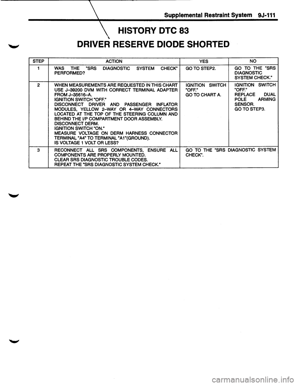
Supplemental Restraint System 9J-111
HISTORY DTC 83
DRIVER RESERVE DIODE SHORTED
STEP
ACTION YES NO
1 WAS THE "SRS
DIAGNOSTIC SYSTEM CHECK" GOTOSTEP2. GO TO THE "SRS
PERFORMED? DIAGNOSTIC
SYSTEM CHECK."
2 WHEN
MEASUREMENTS ARE REQUESTED IN THIS CHART IGNITION SWITCH IGNITION
SWITCH
USE J-39200 DVM WITH CORRECT TERMINAL ADAPTER "OFF." "OFF."
FROM J-35616-A. GO TO CHART A. REPLACE DUAL
IGNITION
SWITCH "OFF." POLE
ARMING
DISCONNECT DRIVER
AND PASSENGER INFLATOR SENSOR.
MODULES, YELLOW 2-WAY OR 4-WAY CONNECTORS GOTOSTEP3.
LOCATED AT THE TOP OF THE STEERING COLUMN AND BEHIND THE liP COMPARTMENT DOOR ASSEMBLY.
DISCONNECT DERM. IGNITION SWITCH "ON."
MEASURE
VOLTAGE ON DERM HARNESS CONNECTOR
TERMINAL "A4" TO TERMINAL "A1"(GROUND). IS VOLTAGE 1 VOLT OR LESS?
3 RECONNECT ALL SRS COMPONENTS, ENSURE ALL GO TO THE "SRS DIAGNOSTIC SYSTEM
COMPONENTS
ARE PROPERLY MOUNTED. CHECK". CLEAR SRS DIAGNOSTIC TROUBLE CODES. REPEAT THE "SRS DIAGNOSTIC SYSTEM CHECK."
Page 1736 of 1928
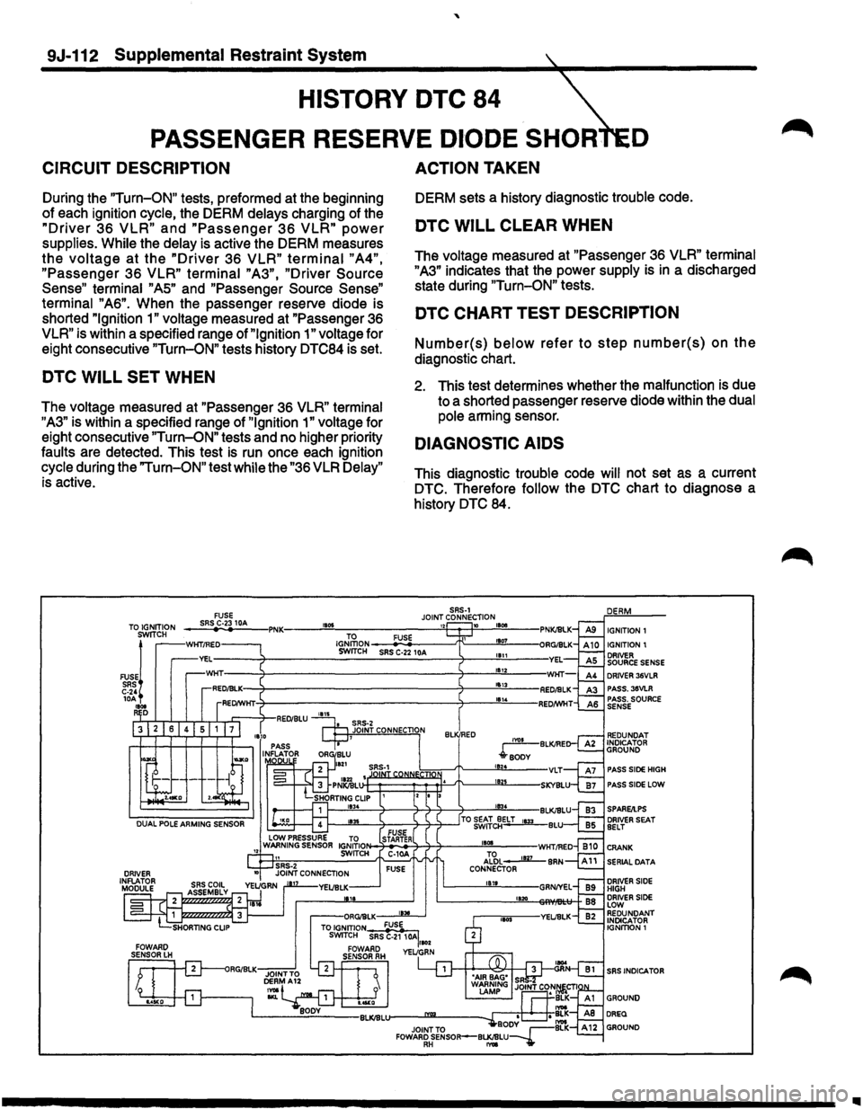
'
9J-112 Supplemental Restraint System
HISTORY DTC 84
PASSENGER RESERVE DIODE SHOR D
CIRCUIT DESCRIPTION
During the "Turn-ON" tests, preformed at the beginning
of each ignition cycle, the DERM delays charging of the
"Driver 36 VLR" and "Passenger 36 VLR" power
supplies. While the delay is active the DERM measures
the voltage at the "Driver 36 VLR" terminal "A4",
"Passenger 36 VLR" terminal "A3", "Driver Source
Sense"
terminal "AS" and "Passenger Source Sense"
terminal "A6". When the passenger reserve diode is
shorted
"Ignition 1" voltage measured at "Passenger 36
VLR" is within a specified range of "Ignition 1" voltage for
eight consecutive
"Turn-ON" tests history DTC84 is set.
DTC WILL SET WHEN
The voltage measured at "Passenger 36 VLR" terminal
"A3" is within a specified range of "Ignition 1" voltage for
eight consecutive
"Turn-ON" tests and no higher priority
faults are detected. This test
is run once each ignition
cycle during the
"Turn-ON" test while the "36 VLR Delay"
is active.
ACTION TAKEN
DERM sets a history diagnostic trouble code.
DTC WILL CLEAR WHEN
The voltage measured at "Passenger 36 VLR" terminal
"A3" indicates that the power supply is in a discharged
state during
"Turn-ON" tests.
DTC CHART TEST DESCRIPTION
Number(s) below refer to step number(s) on the
diagnostic chart.
2. This test determines whether the malfunction is due
to a shorted passenger reserve diode within the dual
pole arming sensor.
DIAGNOSTIC AIDS
This diagnostic trouble code will not set as a current
DTC. Therefore follow the DTC chart to diagnose a
history
DTC 84.
SRS-1 JOINT CONNECTION
IGNITION 1
IGNITION 1 DRIVER SOURCE SENSE DRIVER 36VLR
PASS. 35VLR
PASS. SOURCE
SENSE
PASS SIDE HIGH
PASS
SIDE LOW
f--'""'-----7---3-7-7-~--1!!!i!03!..4 --BLKIBLU SPARE/I.PS
1---""''----4------4-4-4--_JTO ~~:::~ELT 1133 BLU
1101
Al?,L 1127 CONNECTOR
1811
1120
SRS INDICATOR
..