torque ISUZU TROOPER 1995 Workshop Manual
[x] Cancel search | Manufacturer: ISUZU, Model Year: 1995, Model line: TROOPER, Model: ISUZU TROOPER 1995Pages: 1928
Page 1853 of 1928
14. Seat back assembly
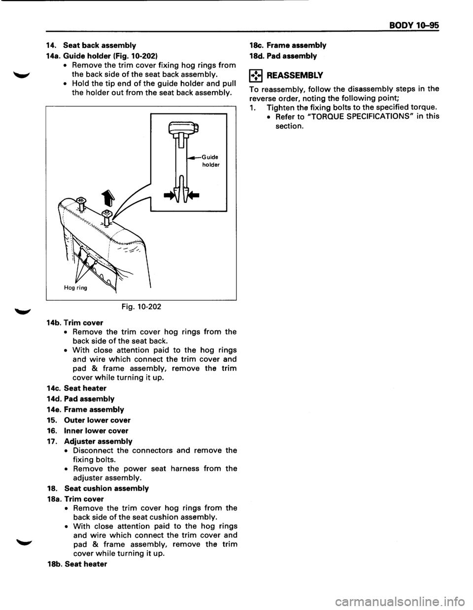
14a. Guide holder (Fig. 10-202)
•
Remove the trim cover fixing hog rings from
the back side of the seat back assembly.
•
Hold the tip end of the guide holder and pull
the holder out from the seat back assembly.
Fig.
10-202
14b. Trim cover
Guide holder
• Remove the trim cover hog rings from the
back side of the seat back.
• With close attention paid to the hog rings
and
wire which connect the trim cover and
pad
& frame assembly, remove the trim
cover while turning it up.
14c.
Seat heater
14d. Pad assembly
14e. Frame assembly
15. Outer lower cover
16.
Inner lower cover
17.
Adjuster assembly
•
Disconnect the connectors and remove the
fixing bolts.
• Remove the power seat harness from the
adjuster assembly.
18.
Seat cushion assembly
18a. Trim cover
• Remove the trim cover hog rings from the
back side of the seat cushion assembly.
• With close attention paid to the hog rings
and
wire which connect the trim cover and
"-"" pad & frame assembly, remove the trim
cover while turning it up.
18b.
Seat heater 18c.
Frame
assembly
18d. Pad assembly
1•:.1 REASSEMBLY
BODY 1Q-95
To reassembly, follow the disassembly steps in the
reverse order, noting
the following point;
1. Tighten the fixing bolts to the specified torque.
• Refer to "TORQUE SPECIFICATIONS" in this
section.
Page 1854 of 1928
10-96 BODY
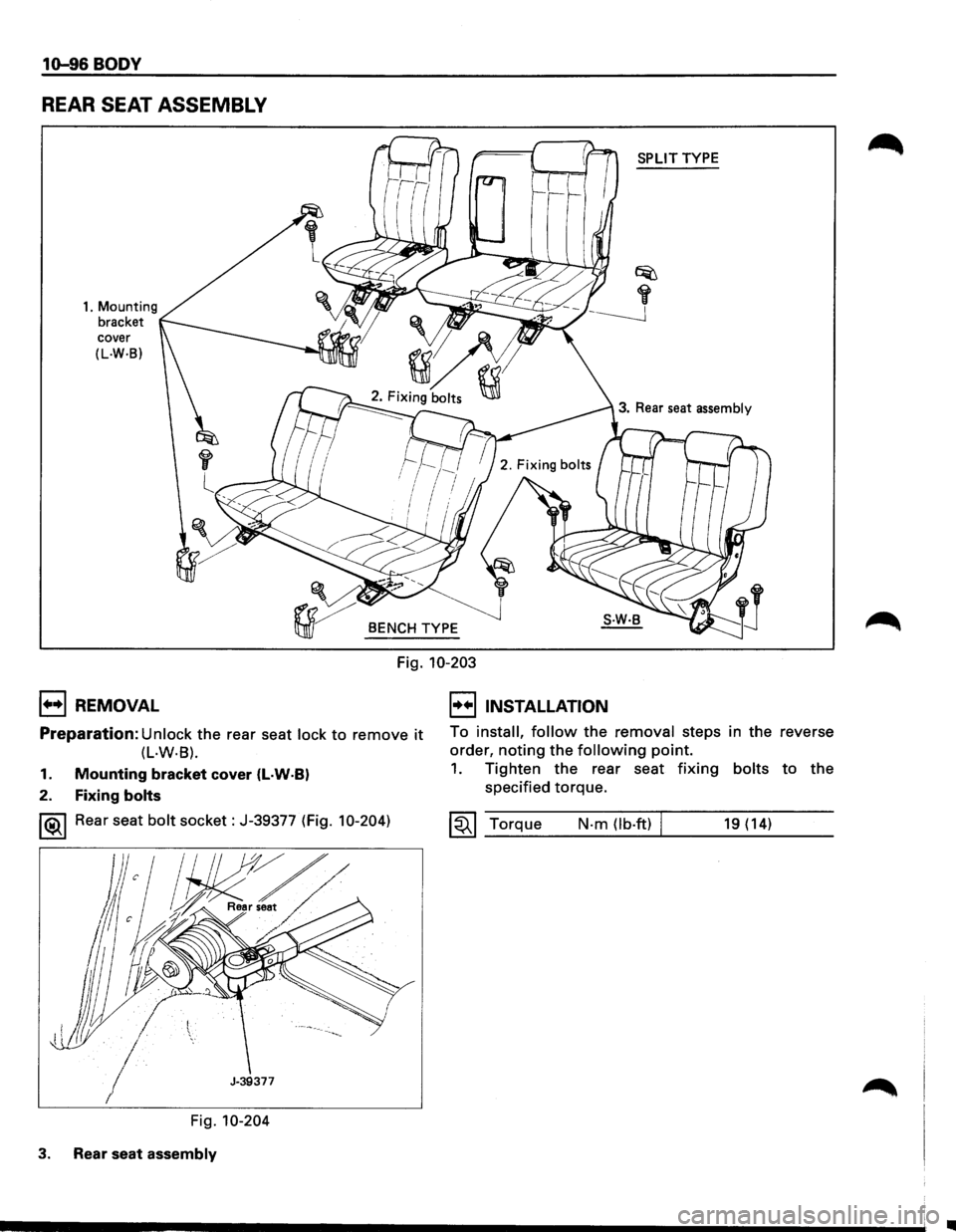
REAR SEAT ASSEMBLY
1. Mounting
bracket
cover
(L.W·B)
1++1 REMOVAL
r
l
SPLIT TYPE
3. Rear seat assembly
BENCH TYPE
Fig. 10-203
I••IINSTALLATION
Preparation: Unlock the rear seat lock to remove it To install, follow the removal steps in the reverse
order, noting the following point. (L·W·B).
1. Mounting bracket cover (l·W·BI
2. Fixing bolts
1®.1 Rear seat bolt socket: J-39377 (Fig. 10-204)
Fig. 10-204
3. Rear seat assembly
1. Tighten the rear seat fixing bolts to the
specified torque.
~~~ Torque N-m (lb-ft) I 19 (14)
..
Page 1856 of 1928
10-98 BODY
6. Connecting shaft
7. Seat back assembly
7a. Band hook cover
7b.
Pillow assembly
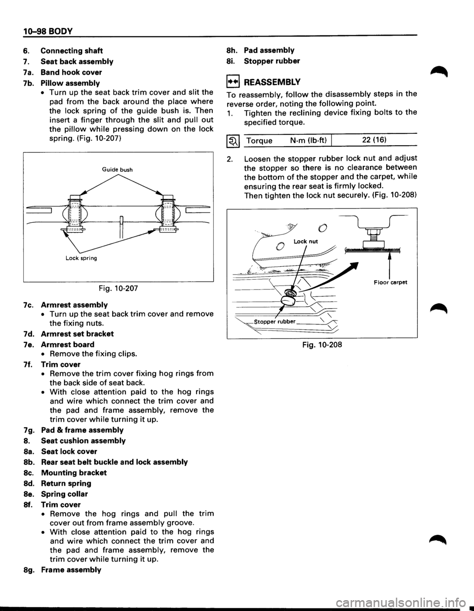
•
Turn up the seat back trim cover and slit the
pad
from the back around the place where
the lock spring of the guide bush is. Then
insert a
finger through the slit and pull out
the pillow while pressing down on the lock
spring. (Fig. 10-207)
Guide bush
Lock spring
Fig. 10-207
7c.
Armrest assembly
• Turn up the seat back trim cover and remove
the fixing nuts.
7d.
Armrest set bracket
7e. Armrest board
• Remove the fixing clips.
7f. Trim cover
• Remove the trim cover fixing hog rings from
the back side of seat back.
• With close attention paid to the hog rings
and
wire which connect the trim cover and
the pad and
frame assembly, remove the
trim cover while turning it up.
7g. Pad
& frame assembly
8. Seat cushion assembly
Sa. Seat lock cover
Sb. Rear seat belt buckle and lock assembly
Sc. Mounting bracket
Sd. Return spring
Se. Spring collar
Sf. Trim cover
• Remove the hog rings and pull the trim
cover out from frame assembly groove.
• With close attention paid to the hog rings
and
wire which connect the trim cover and
the pad and frame assembly, remove the
trim cover while turning it up.
Sg. Frame assembly
Sh. Pad assembly
Si. Stopper rubber
1++1 REASSEMBLY
To reassembly, follow the disassembly steps in the
reverse order, noting the following point.
1. Tighten the reclining device fixing bolts to the
specified torque.
~~~ Torque N-m (lb.ft) 22 (16)
2. Loosen the stopper rubber lock nut and adjust
the stopper so there is no clearance between
the bottom of the stopper and the carpet, while
ensuring the rear seat is firmly locked.
Then tighten the lock nut securely. (Fig. 10-208)
0
0
Lock nut
F Iocr carpet
Fig. 10-208
Page 1858 of 1928
1Q-100 BODY
&d. Arm ret set assembly
&e. Arm rest board
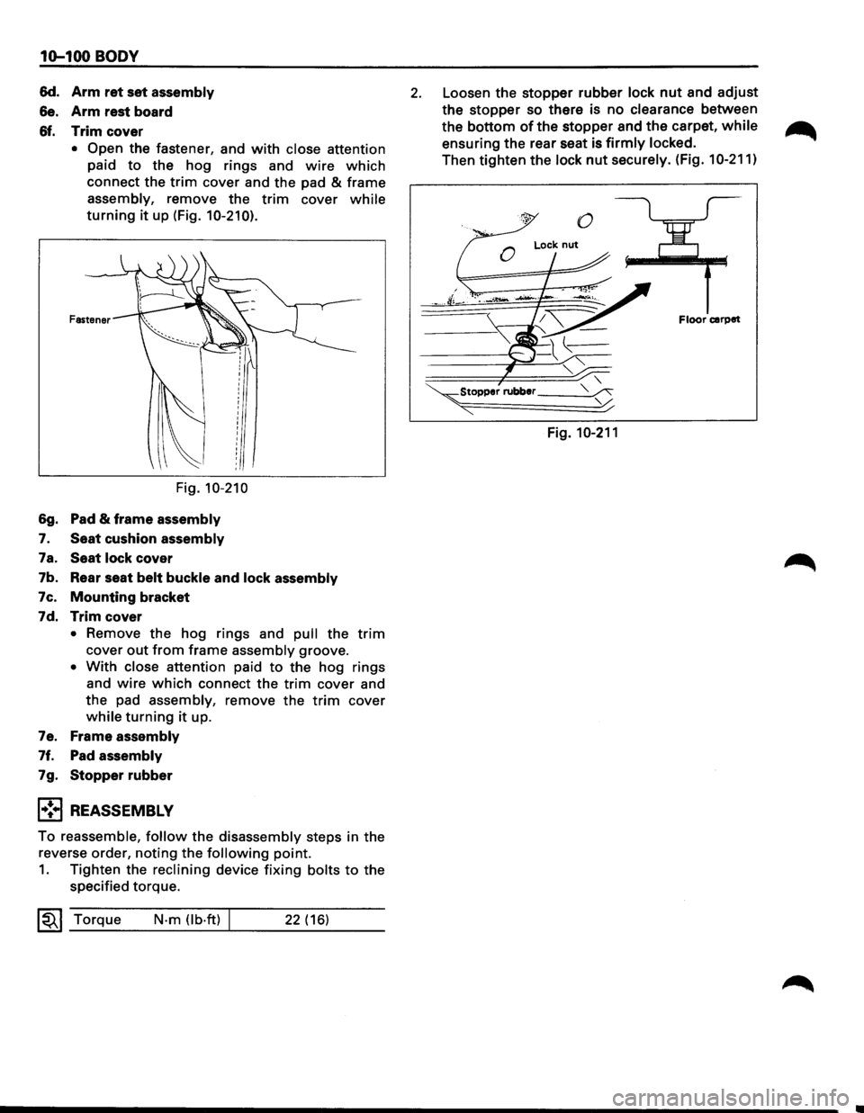
&f. Trim cover
• Open the fastener, and with close attention
paid
to the hog rings and wire which
connect the trim cover and the pad & frame
assembly, remove the trim cover while
turning it up (Fig. 10-210).
Fastener
Fig. 10-210
&g. Pad & frame assembly
7. Seat cushion assembly
7a. Seat lock cover
7b. Rear seat
belt buckle and lock assembly
7c.
Mounting bracket
7d.
Trim cover
• Remove the hog rings and pull the trim
cover out from frame assembly groove.
• With close attention paid to the hog rings
and
wire which connect the trim cover and
the pad
assembly, remove the trim cover
while turning it up.
7e. Frame
assembly
7f. Pad assembly
7g. Stopperrubber
l•!•l REASSEMBLY
To reassemble, follow the disassembly steps in the
reverse order,
noting the following point.
1. Tighten the reclining device fixing bolts to the
specified torque.
~~~ Torque N-m (lb-ft) 22 (16)
2. Loosen the stopper rubber lock nut and adjust
the
stopper so there is no clearance between
the
bottom of the stopper and the carpet, while
ensuring the rear seat is firmly locked.
Then tighten the lock nut securely. (Fig. 10-211)
Floor carpet
~Stopper rubber __ _
"""' Fig. 10-211
Page 1860 of 1928
10-102 BODY
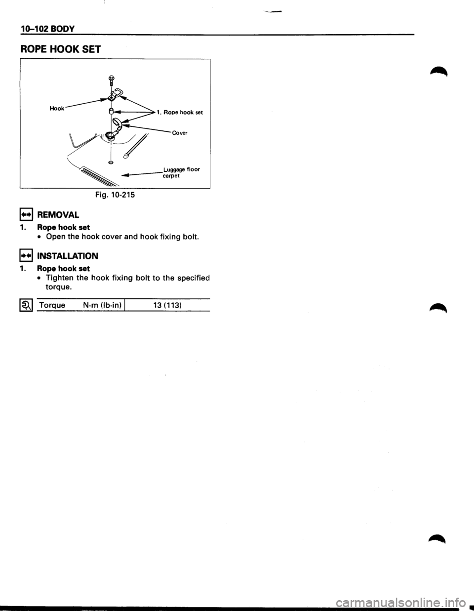
ROPE HOOK SET
Hook
Cover
Luggage floor ------carpet
Fig. 10-215
1••1 REMOVAL
1. Rope hook set
• Open the hook cover and hook fixing bolt.
I••! INSTALLATION
1. Rope hook set
• Tighten the hook fixing bolt to the specified
torque.
1~1 Torque N·m Ob·in) I 13(113)
Page 1861 of 1928
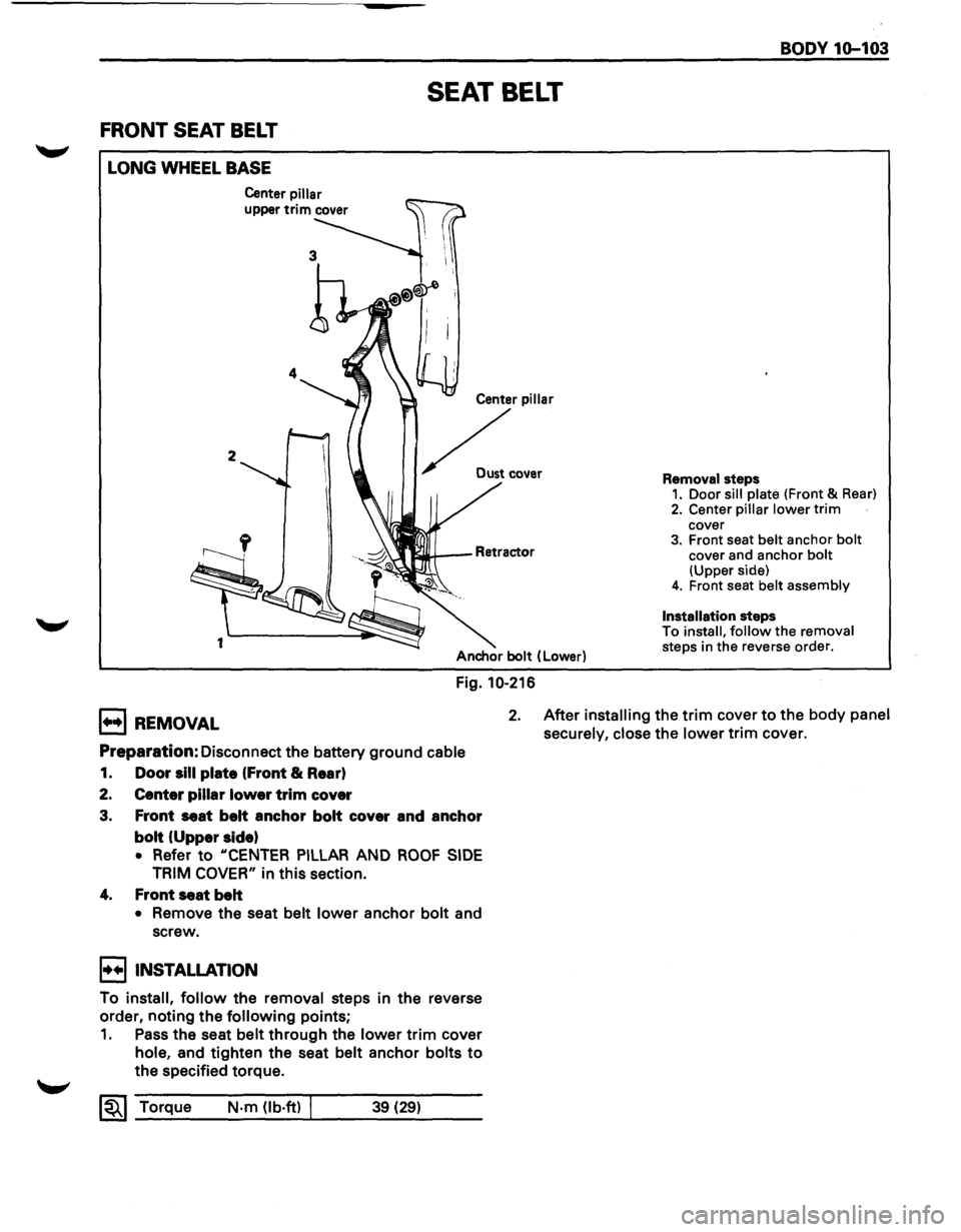
FRONT SEAT BELT
LONG WHEEL BASE
2
1
Center pillar
upper trim cover
SEAT BELT
Center pillar
~ .....
Anchor bolt (Lower)
Fig. 10-216
BODY 1Q-103
Removal steps 1. Door sill plate (Front & Rear)
2. Center pillar lower trim cover 3. Front seat belt anchor bolt cover and anchor bolt (Upper side) 4. Front seat belt assembly
Installation
steps
To install, follow the removal
steps in the reverse order.
B REMOVAL 2. After installing the trim cover to the body panel
securely, close
the lower trim cover.
Preparation: Disconnect the battery ground cable
1. Door sill plate (Front & Rear)
2. Center pillar lower trim cover
3. Front seat belt anchor bolt cover and anchor
bolt (Upper side)
• Refer to "CENTER PILLAR AND ROOF SIDE
TRIM COVER" in this section.
4. Front seat belt
• Remove the seat belt lower anchor bolt and
screw.
I••IINSTALLATION
To install, follow the removal steps in the reverse
order, noting the
following points;
1. Pass the seat belt through the lower trim cover
hole, and tighten the seat belt anchor bolts to
the specified torque.
~~~ Torque N·m (lb·ft) I 39 (29)
Page 1862 of 1928
----
10-104 BODY
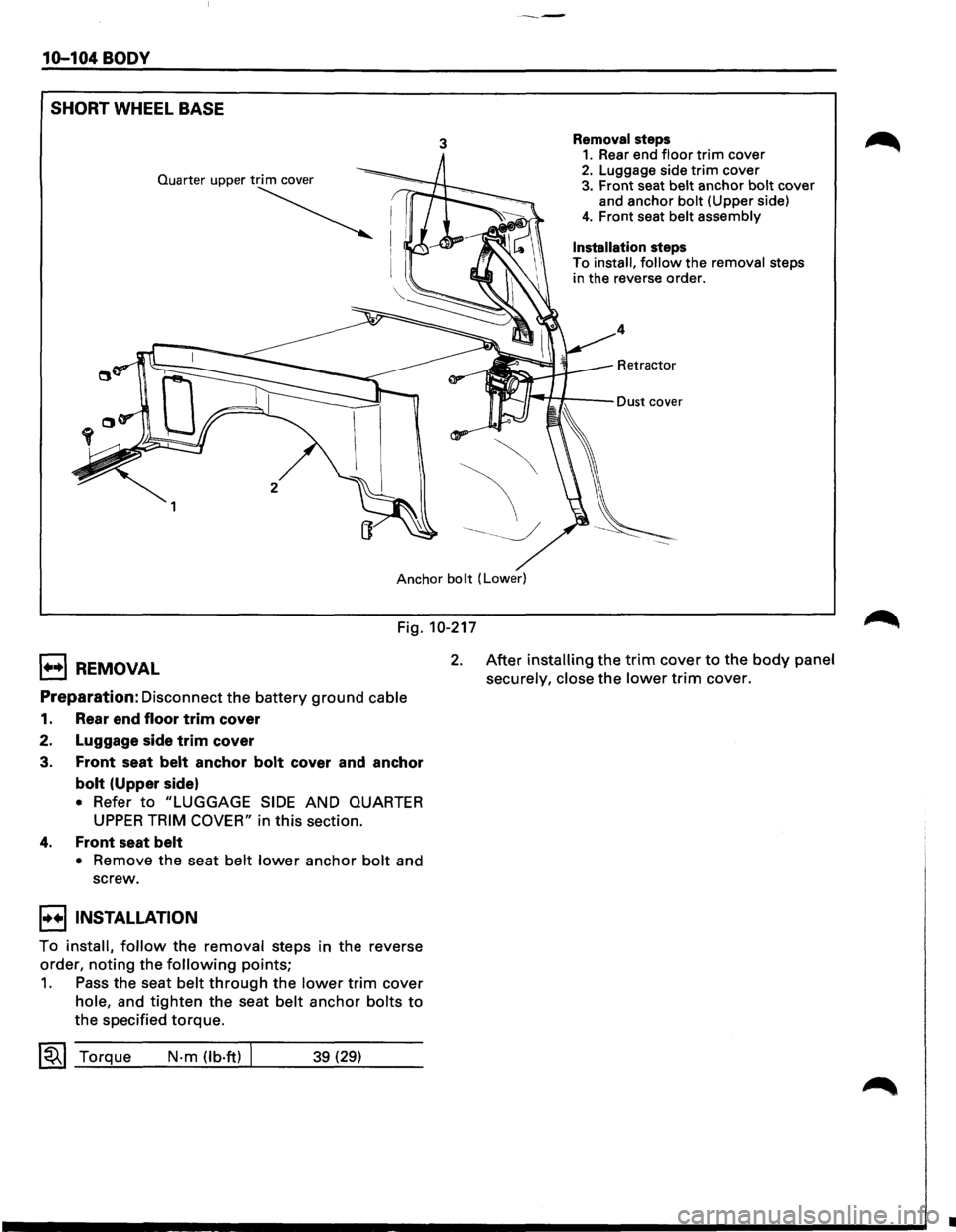
SHORT
WHEEL BASE
3 Removal steps 1. Rear end floor trim cover 2. Luggage side trim cover 3. Front seat belt anchor bolt cover
and anchor bolt (Upper side)
4. Front seat belt assembly
Installation steps
To install, follow the removal steps
in the reverse order.
4
Retractor
Anchor bolt (Lower)
Fig. 10-217
1++1 REMOVAL
Preparation: Disconnect the battery ground cable
1. Rear end floor trim cover
2. Luggage side
trim cover
3.
Front seat belt anchor bolt cover and anchor
bolt (Upper side)
• Refer to "LUGGAGE SIDE AND QUARTER
UPPER TRIM COVER" in this section.
4. Front seat belt
• Remove the seat belt lower anchor bolt and
screw.
I••IINSTALLATION
To install, follow the removal steps in the reverse
order,
noting the following points;
1. Pass the seat belt through the lower trim cover
hole, and tighten the seat belt anchor bolts to
the specified torque.
~~~ Torque N-m (lb·ft) 39 (29)
2. After installing the trim cover to the body panel
securely, close
the lower trim cover.
•
Page 1863 of 1928
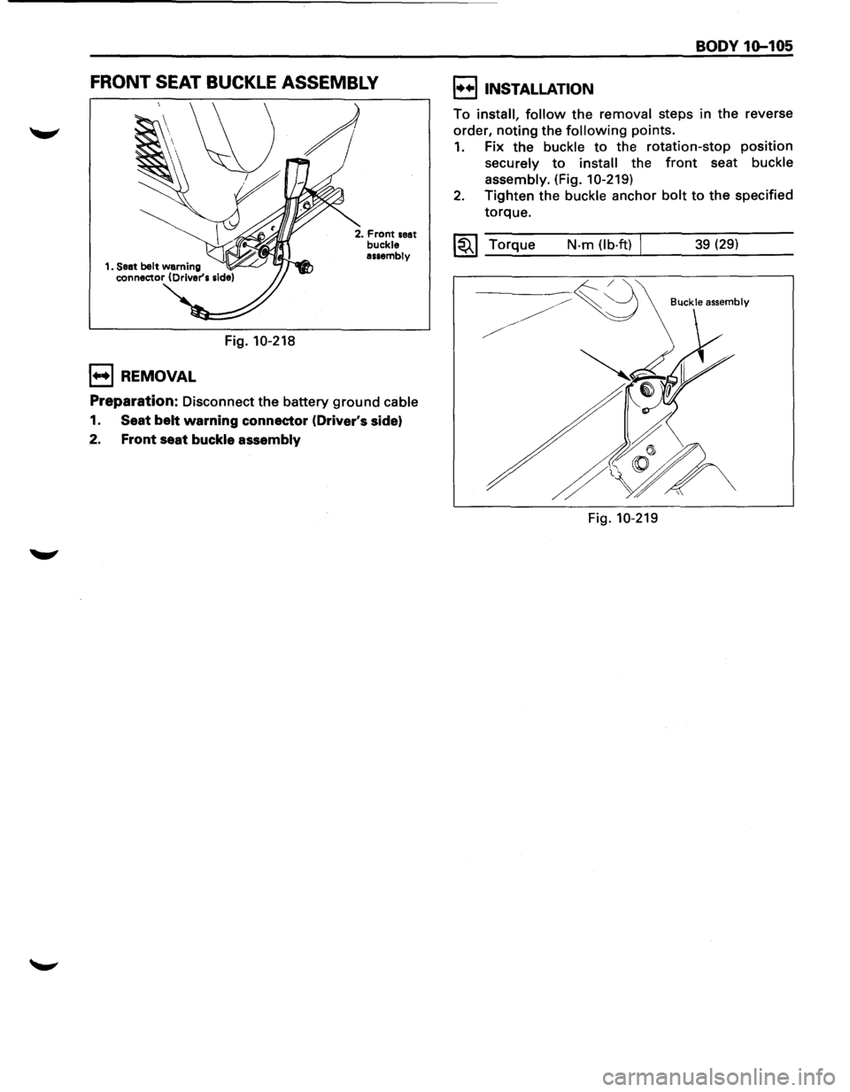
FRONT SEAT BUCKLE ASSEMBLY
Fig. 10-218
1++1 REMOVAL
2. Front seat buckle assembly
Preparation: Disconnect the battery ground cable
1. Seat belt warning connector (Driver's side)
2. Front seat buckle assembly
BODY 1Q-105
I••IINSTALLATION
To install, follow the removal steps in the reverse
order, noting the following points.
1. Fix the buckle to the rotation-stop position
securely to install the front seat buckle
assembly.
(Fig. 10-219)
2. Tighten the buckle anchor bolt to the specified
torque.
~~~ Torque N·m (lb·ft) I 39 (29)
Buckle assembly
Fig. 10-219
Page 1864 of 1928
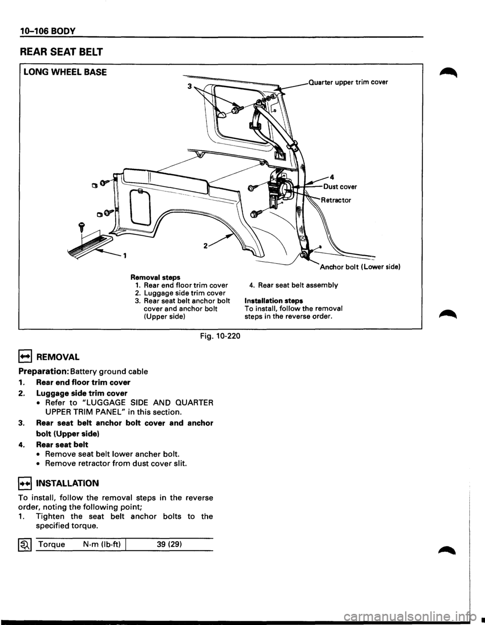
10-106 BODY
REAR SEAT BELT
LONG WHEEL BASE
B REMOVAL
Removal steps 1. Rear end floor trim cover 2. Luggage side trim cover
3. Rear seat belt anchor bolt cover and anchor bolt (Upper side)
Fig. 10-220
Preparation: Battery ground cable
1. Rear end floor trim cover
2. Luggage side
trim cover
• Refer to "LUGGAGE SIDE AND QUARTER
UPPER TRIM PANEL" in this section.
3. Rear seat belt anchor bolt cover and anchor
bolt (Upper side)
4. Rear seat belt
• Remove seat belt lower ancher bolt.
•
Remove retractor from dust cover slit.
I••IINSTALLATION
To install, follow the removal steps in the reverse
order,
noting the following point;
1. Tighten the seat belt anchor bolts to the
specified torque.
~~~ Torque N·m (lb.ft) 39 (29)
Quarter upper trim cover
4. Rear seat belt assembly
Installation steps
To install, follow the removal steps in the reverse order.
•
Page 1866 of 1928
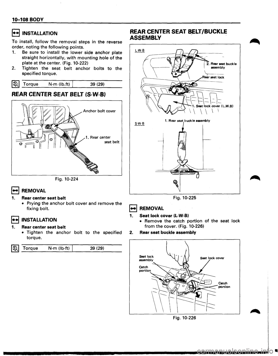
10-108 BODY
!••I INSTALLATION
To install, follow the removal steps in the reverse
order,
noting the following points.
1. Be sure to install the lower side anchor plate
straight horizontally, with mounting hole of the
plate at the center. (Fig. 10-222)
2. Tighten the seat belt anchor bolts to the
specified torque.
~~~ Torque N·m (lb.ft) / 39 (29)
REAR CENTER SEAT BELT (S·W·B)
Anchor bolt cover
1. Rear center
seat
belt
Fig. 10-224
1••1 REMOVAL
1. Rear center seat belt
• Prying the anchor bolt cover and remove the
fixing bolt.
I••IINSTALLATION
1. Rear center seat belt
• Tighten the anchor bolt to the specified
torque.
~~~ Torque N-m (lb·ft) 39 (29)
REAR CENTER SEAT ~LT/BUCKLE
ASSEMBLY
1••1 REMOVAL
2. Rear seat buckle
assembly
\----Rear seat lock
--t\8~ 1. Seat lock cover (L.W.B)
1. Rear seat buckle assembly
Fig. 10-225
1. Seat lock cover (L·W·B)
• Remove the catch portion of the seat lock
from the cover. (Fig. 10-226)
2. Rear seat buckle assembly
Catch
portion
Fig. 10-226
Catch
portion
•