torque ISUZU TROOPER 1995 Workshop Manual
[x] Cancel search | Manufacturer: ISUZU, Model Year: 1995, Model line: TROOPER, Model: ISUZU TROOPER 1995Pages: 1928
Page 1802 of 1928
10-44 BODY
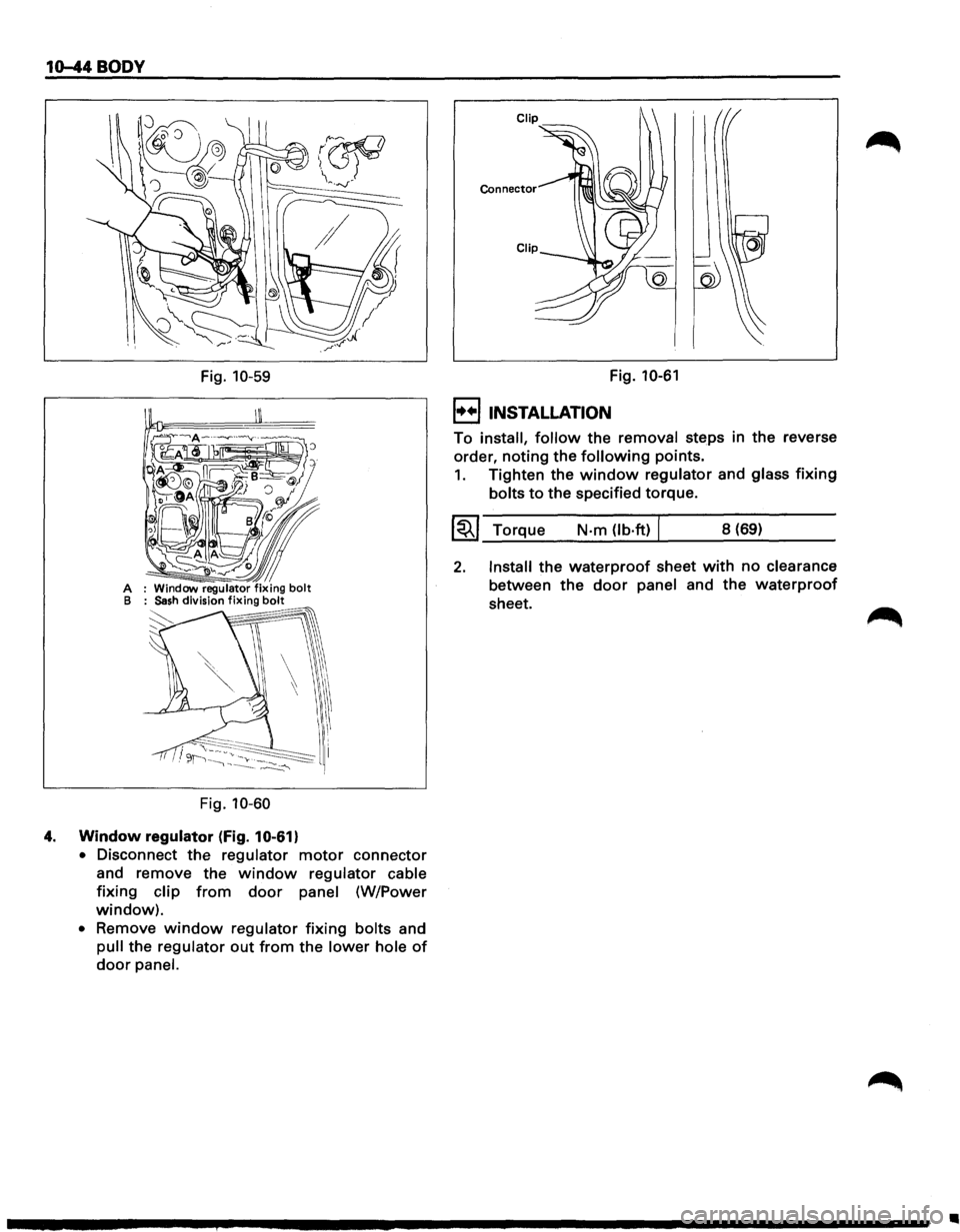
A B
Fig. 10-59
Fig. 10-60
4. Window regulator (fig. 10-61)
• Disconnect the regulator motor connector
and remove the
window regulator cable
fixing clip from door panel (W/Power
window).
• Remove window regulator fixing bolts and
pull the regulator
out from the lower hole of
door panel. Fig.
10-61
I••! INSTALLATION
To
install, follow the removal steps in the reverse
order,
noting the following points.
1. Tighten the window regulator and glass fixing
bolts to the specified torque.
~~~ Torque N·m (lb·ft) I 8 (69)
2. Install the waterproof sheet with no clearance
between
the door panel and the waterproof
sheet.
•
Page 1803 of 1928
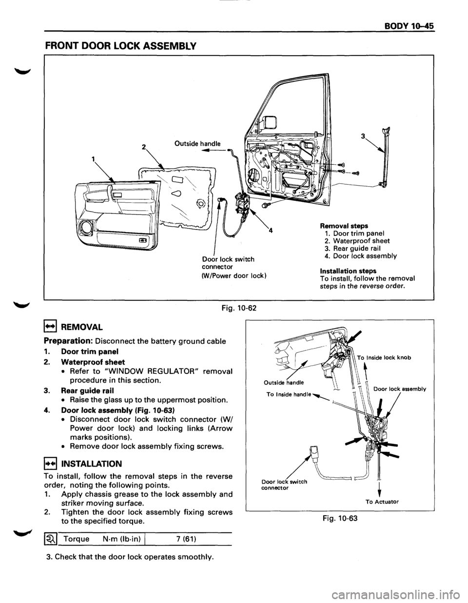
FRONT DOOR LOCK ASSEMBLY
2 Outside handle ...
Door lock switch
connector
(W/Power
door lock)
Fig. 10-62
1++1 REMOVAL
Preparation: Disconnect the battery ground cable
1. Door trim panel
2. Waterproof sheet
• Refer to "WINDOW REGULATOR" removal
procedure in this section.
3. Rear
guide rail
•
Raise the glass up to the uppermost position.
4. Door lock assembly (Fig. 10-63)
• Disconnect door lock switch connector (W/
Power
door lock) and locking links (Arrow
marks positions).
• Remove door lock assembly fixing screws.
I++IINSTALLATION
To install, follow the removal steps in the reverse
order, noting the following points.
1. Apply chassis grease to the lock assembly and
striker
moving surface.
2. Tighten the door lock assembly fixing screws
to the specified torque.
~~~ Torque N·m Ob·in) I 7 (61)
3. Check that the door lock operates smoothly.
Outside handle
Door lock switch
connector
BODY 10-45
Removal steps 1. Door trim panel 2. Waterproof sheet 3. Rear guide rail 4. Door lock assembly
Installation steps To install, follow the removal steps in the reverse order.
To Inside lock knob
'
To Actuator
Fig. 10-63
Page 1804 of 1928
10-46 BODY
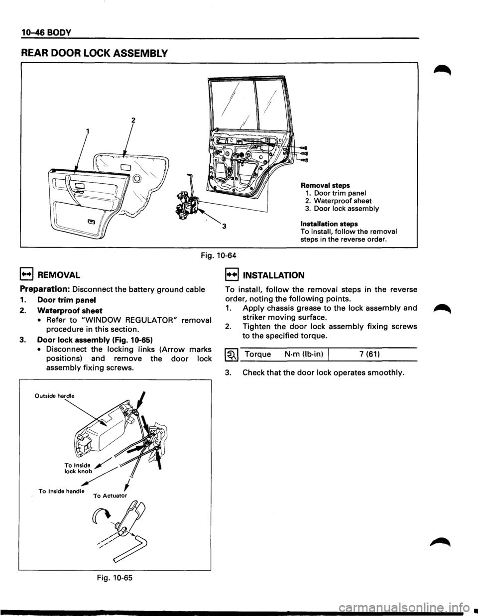
REAR DOOR LOCK ASSEMBLY
2
3
Removal steps
1. Door trim panel 2. Waterproof sheet 3. Door lock assembly
Installation steps To install, follow the removal
steps in the reverse order.
1++1 REMOVAL
Fig. 10-64
I++IINSTALLATION
Preparation: Disconnect the battery ground cable
1. Door trim panel
2. Waterproof sheet
• Refer to "WINDOW REGULATOR" removal
procedure in this section.
3. Door lock assembly (Fig. 10-65)
• Disconnect the locking links (Arrow marks
positions) and remove the
door lock
assembly
fixing screws.
Tolns~~~~ lockk/
To Inside handle I To Actuator
((\/Z
----~
/ / / / /
Fig. 10-65
To install, follow the removal steps in the reverse
order,
noting the following points.
1. Apply chassis grease to the lock assembly and
striker
moving surface.
2. Tighten the door lock assembly fixing screws
to the specified torque.
~~~ Torque N-m (lb·in) I 7 (61)
3. Check that the door lock operates smoothly.
•
Page 1806 of 1928
10-48 BODY
I••! INSTALLATION
To install, follow the removal steps in the reverse
order,
noting the following points.
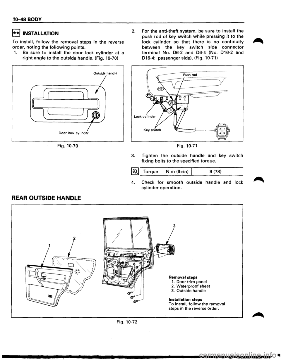
1. Be sure to install the door lock cylinder at a
right angle to the outside handle. (Fig. 10-70)
Outside handle
Door lock cylinder
Fig. 10-70
REAR OUTSIDE HANDLE
2 I
2. For the anti-theft system, be sure to install the
push rod
of key switch while pressing it to the
lock cylinder so that there is no continuity
between the key switch side connector
terminal No. 06-2 and 06-4 (No. 016-2 and
016-4: passenger side). (Fig.
10-71)
3.
Fig. 10-71
Tighten the outside handle and key switch
fixing bolts to the specified torque.
~~~ Torque N·m (lb·in) j 9 (78)
4. Check for smooth outside handle and lock
cylinder operation.
!
Removal steps 1. Door trim panel 2. Waterproof sheet 3. Outside handle
Installation steps To install, follow the removal
steps in the reverse order.
Fig. 10-72
•
Page 1807 of 1928
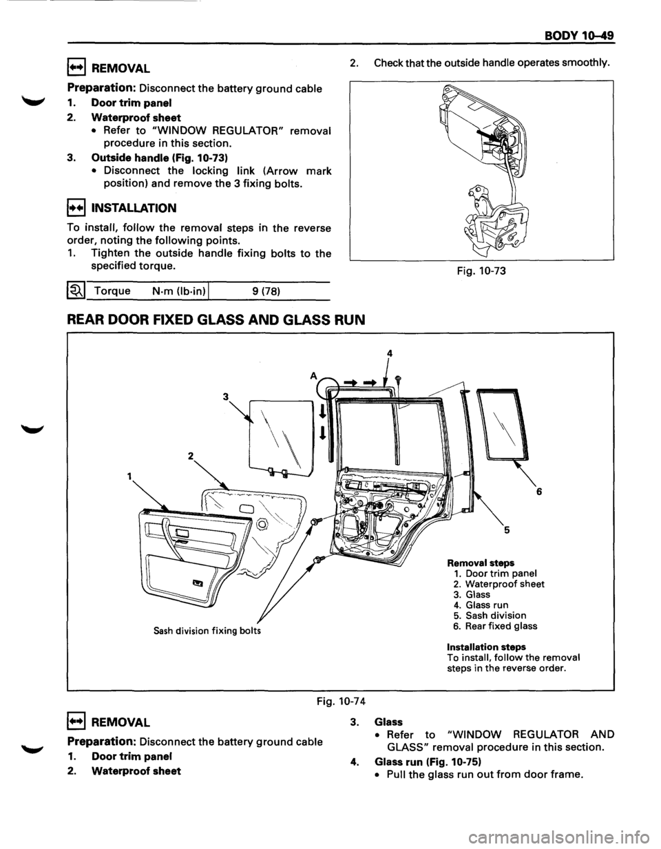
1••1 REMOVAL
Preparation: Disconnect the battery ground cable
'--' 1. Door trim panel
2.
Waterproof sheet
• Refer to "WINDOW REGULATOR" removal
procedure in this section.
3.
Outside handle (Fig. 10-73)
•
Disconnect the locking link (Arrow mark
position) and remove
the 3 fixing bolts.
I••! INSTALLATION
To install, follow the removal steps in the reverse
order,
noting the following points.
1. Tighten the outside handle fixing bolts to the
specified torque.
1~1 Torque N·m Ob·in) I 9 (78)
BODY 10-49
2. Check that the outside handle operates smoothly.
Fig. 10-73
REAR DOOR FIXED GLASS AND GLASS RUN
4
3
1
Sash division fixing bolts
6
5
Removal steps 1. Door trim panel 2. Waterproof sheet
3. Glass 4. Glass run 5. Sash division 6. Rear fixed glass
Installation steps To install, follow the removal
steps in the reverse order.
Fig. 10-74
1+•1 REMOVAL
Preparation: Disconnect the battery ground cable
1. Door trim panel
2. Waterproof sheet
3. Glass
• Refer to "WINDOW REGULATOR AND
GLASS" removal procedure in this section.
4. Glass run (Fig. 10-75)
• Pull
the glass run out from door frame.
Page 1813 of 1928
1••1 REMOVAL
Preparation: Battery ground cable
1. Rear door sill plate and luggage side lower
cover
2. Rear
door seal finisher
• Pull the finisher out from body panel. (Fig.
10-94)
I++IINSTALLATION
2. Rear door seal finisher
• Insert the finisher into the @ corner and
install the finisher in the arrow-marked
directions. (Fig.
10-95)
1. Rear door sill plate and luggage side lower
cover
• Be careful not to allow the sill plate and the
cover
to distort or twist the finisher.
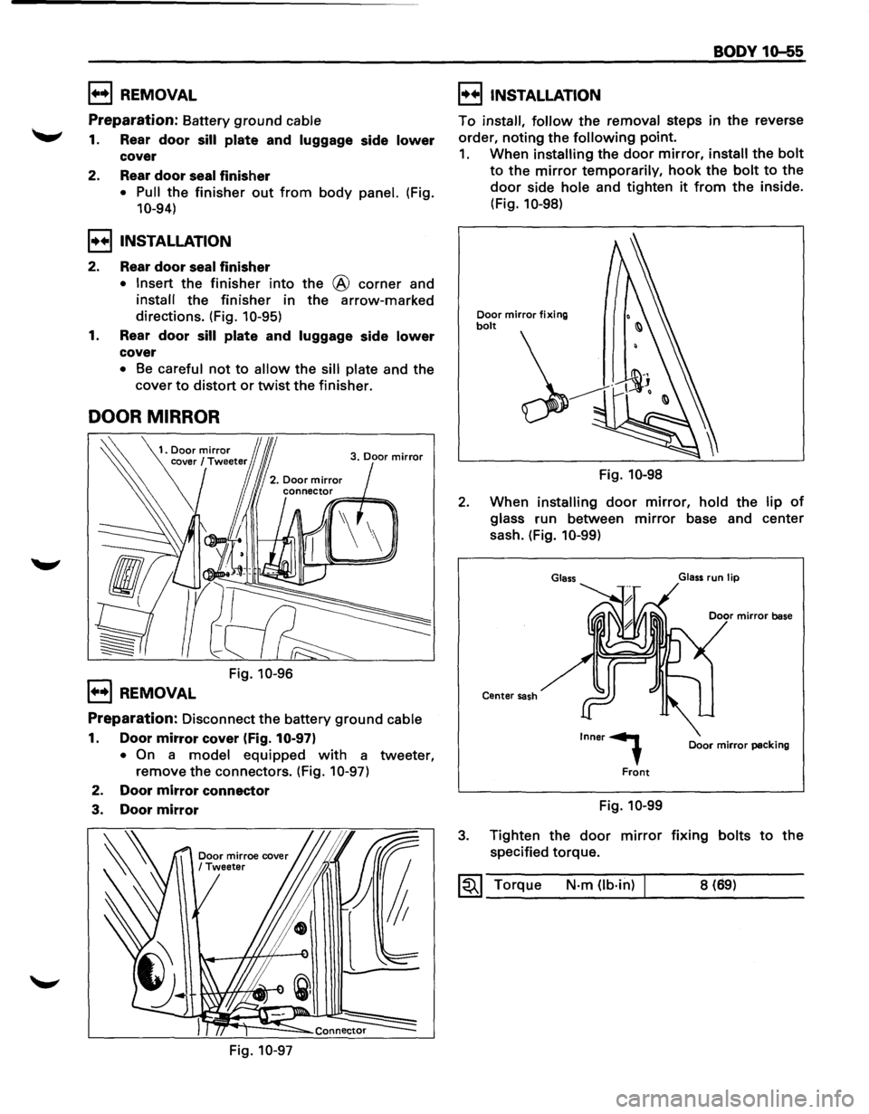
DOOR MIRROR
3. Door mirror
1+•1 REMOVAL
Fig. 10-96
Preparation: Disconnect the battery ground cable
1. Door mirror cover (Fig. 10-97)
• On a model equipped with a tweeter,
remove
the connectors. (Fig. 10-97)
2. Door mirror connector
3. Door mirror
Fig. 10-97
BODY 10-55
I++IINSTALLATION
To install, follow the removal steps in the reverse
order,
noting the following point.
1. When installing the door mirror, install the bolt
to the mirror temporarily, hook the bolt to the
door side hole and tighten it from the inside.
(Fig.
10-98)
Door mirror fixing bolt
Fig. 10-98
2. When installing door mirror, hold the lip of
glass run between mirror base and center
sash. (Fig.
10-99)
Glass
Center sash
Inner,
Front
Fig. 10-99
Glass run lip
Door mirror packing
3. Tighten the door mirror fixing bolts to the
specified torque.
~~~ Torque N·m Ob·hl) 8 (69)
Page 1815 of 1928
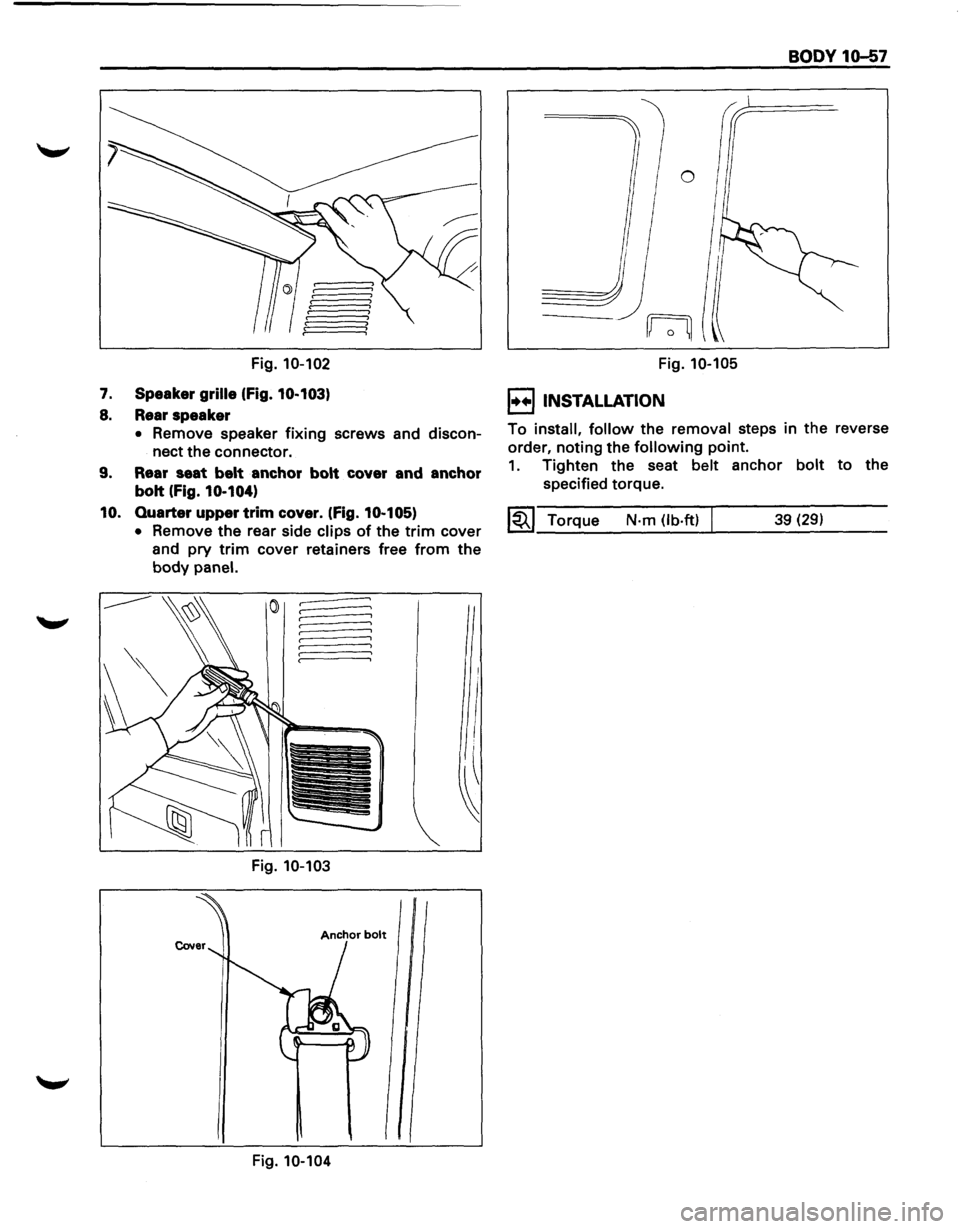
Fig. 10-102
7. Speaker grille (Fig. 10-103)
8. Rear speaker
• Remove speaker fixing screws and discon
nect
the connector.
9. Rear seat belt anchor bolt cover and anchor
bolt
(Fig. 10-104)
10.
Quarter upper trim cover. (Fig. 10-105)
• Remove the rear side clips of the trim cover
and
pry trim cover retainers free from the
body panel.
Fig. 10-103
Anchor bolt
Fig. 10-104
I
~
Fig. 10-105
I+•IINSTALLATION
BODY 10-57
To install, follow the removal steps in the reverse
order, noting the
following point.
1. Tighten the seat belt anchor bolt to the
specified torque.
~~~ Torque N·m (lb·ftl 39 (29)
Page 1818 of 1928
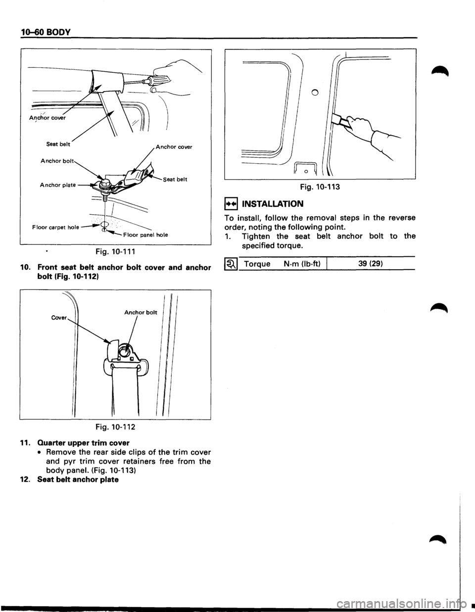
10-60 BODY
Seat belt
Anchor bolt
Seat belt Anchor plate
Fig. 10-111
10. Front seat belt anchor bolt cover and anchor
bolt (Fig. 10-1121
Fig. 10-112
11. Quarter upper trim cover
• Remove the rear side clips of the trim cover
and
pyr trim cover retainers free from the
body panel. (Fig. 10-113)
12. Seat belt anchor plate
Fig. 10-113
I••! INSTALLATION
To install, follow the removal steps in the reverse
order,
noting the following point.
1. Tighten the seat belt anchor bolt to the
specified torque.
~~~ Torque N·m (lb·ftl 39 (29)
•
Page 1820 of 1928
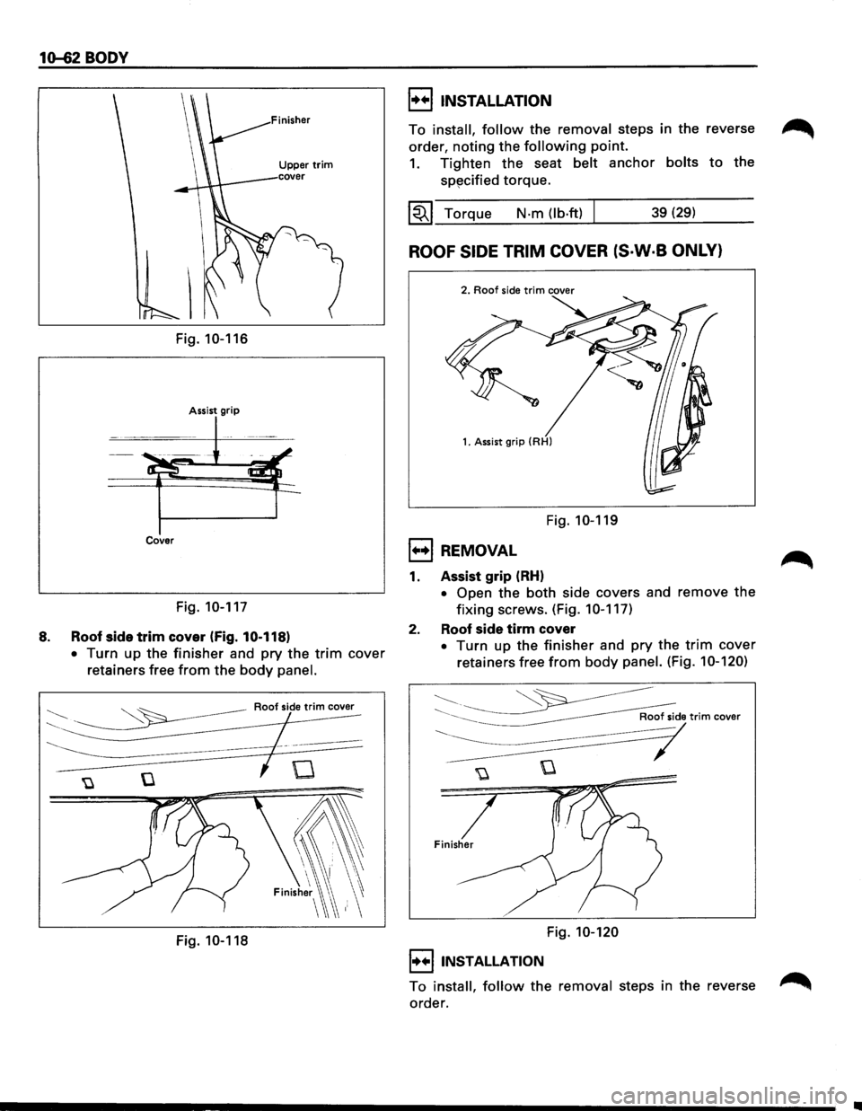
1~2BODY
Fig. 10-116
Assist grip
Cover
Fig. 10-117
8. Roof side trim cover (Fig. 10-118)
•
Turn up the finisher and pry the trim cover
retainers free
from the body panel.
~ -~ Roofsidetrim cover
~=1TF "U G 0
Fig. 10-118
l++liNSTALLATION
To install, follow the removal steps in the reverse ~
order, noting the following point.
1. Tighten the seat belt anchor bolts to the
sp~cified torque.
~~~ Torque N·m (lb·ft) I 39 (29)
ROOF SIDE TRIM COVER (S·W·B ONLY)
2. Roof side trim cover
Fig. 10-119
B REMOVAL
1. Assist grip (RH)
• Open the both side covers and remove the
fixing screws. (Fig. 10-117)
2. Roof side tirm cover
• Turn up the finisher and pry the trim cover
retainers free
from body panel. (Fig. 10-120)
Fig. 10-120
l++liNSTALLATION
To install, follow the removal steps in the reverse ~
order.
Page 1831 of 1928
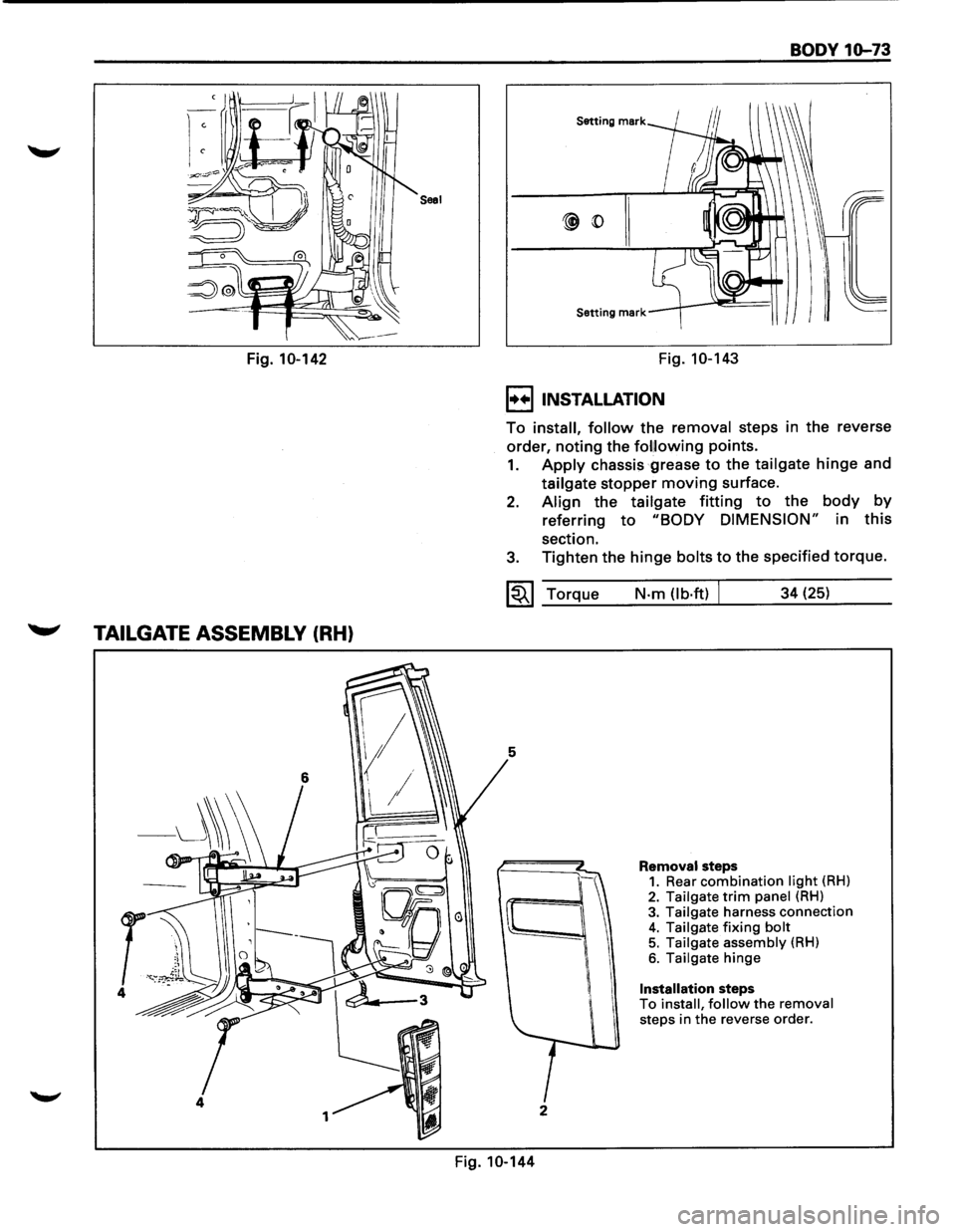
Saal
Fig. 10-142
~ TAILGATE ASSEMBLY (RH)
4
1
BODY 10-73
Setting mark
Setting mark
Fig. 10-143
I••IINSTALLATION
To install, follow the removal steps in the reverse
order,
noting the fol!lowing points.
1. Apply chassis grease to the tailgate hinge and
tailgate stopper
moving surface.
2. Align the tailgate fitting to the body by
referring to "BODY DIMENSION" in this
section.
3. Tighten the hinge bolts to the specified torque.
~~~ Torque
5
I
2
Fig. 10-144
N·m (lb·ftl J 34 (25)
Removal steps 1. Rear combination light (RH) 2. Tailgate trim panel (RH)
3. Tailgate harness connection 4. Tailgate fixing bolt 5. Tailgate assembly (RH)
6. Tailgate hinge
Installation steps To install, follow the removal steps in the reverse order.