battery ISUZU TROOPER 1995 Owner's Guide
[x] Cancel search | Manufacturer: ISUZU, Model Year: 1995, Model line: TROOPER, Model: ISUZU TROOPER 1995Pages: 1928
Page 211 of 1928
SUPPLEMENTAL RESTRAINT SYSTEM (SRSl STEERING WHEEL & COLUMN 3F4-1
SECTION 3F4
SUPPLEMENTAL RESTRAINT SYSTEM
STEERING
WHEEL & COLUMN
W CAUTION:
When fasteners are removed, always reinstall them at the same location from which they were removed.
If a fastener needs to be replaced, use the correct part number fastener for that application. If the correct
part
number fastener is not available, a fastener of equal size and strength (or stronger) may be used.
Fasteners
that are not reused, and those requiring thread locking compound, will be called out. The correct
torque value must be used when installing fasteners that require it. If the above conditions are not
followed, parts or system damage could result.
CONTENTS
General Description .......................................... 3F4-1
Lock Cylinder Replacement ......................... 3F4-10
On-Vehicle Service
............................................ 3F4-2 Steering Column Replacement .................... 3F4-13
Special Service Precaution ........................... 3F4-2 Main Data and Specifications .......................... 3F4-17
Inflator Module Replacement ...................... 3F4-3 Torque
Specifications ................................... 3F4-17
Steering Wheel Replacement ...................... 3F4-4 Special Tools ..................................................... 3F4-17
Combination
Switch Replacement ............. 3F4-7
GENERAL DESCRIPTION
W WARNING
TO AVOID DEPLOYMENT WHEN TROUBLE
SHOOTING
THE SRS SYSTEM, DO NOT USE
ELECTRICAL TEST EQUIPMENT, SUCH AS
BATTERY-POWERED OR A/C-POWERED VOLT
METER, OHMMETER, ETC., OR ANY TYPE OF
ELECTRICAL EQUIPMENT OTHER THAN SPE
CIFIED IN THIS MANUAL. DO NOT USE A NON
POWERED
PROBE-TYPE TESTER.
INSTRUCTION IN THIS MANUAL MUST BE
FOLLOWED CAREFULLY, OTHERWISE PER
SONAL INJURY MAY RESULT.
This steering
wheel and column repair section covers
the Supplemental Restraint System (SRS) steering
column. The following repair procedures are specific
to SRS Components. When servicing a vehicle
equipped with Supplemental Restraint System, pay
close attention to all WARNINGS and CAUTIONS.
For detailed explanation about SRS, refer to Section
9J "SUPPLEMENTAL
RESTRAINT SYSTEM (SRS)" of
this manual.
The steering column has three important features in
addition to the steering function:
1. The column is energy absorbing, designed to
compress in a front-end collision to minimize the
possibility of injury to the driver of the vehicle.
2. The ignition switch and lock are mounted con
veniently on the column.
3. With the column mounted lock, the ignition and
steering operation can be
locked to prevent theft
of the vehicle.
The column may be disassembled and reassembled.
To insure the energy absorbing action, it is important
that the specified screws, bolts and nuts be used only
as designated and that they are tightened to the
specified torque.
When the column is removed from the vehicle, a
sharp
blow on the end of steering shaft or shift lever,
leaning
on the column assembly, or dropping the
assembly could shear or loosen the fasteners that
maintain column rigidity.
Page 213 of 1928
SUPPLEMENTAL RESTRAINT SYSTEM (SRS) STEERING WHEEL & COLUMN 3F4-3
INFLATOR MODULE REPLACEMENT
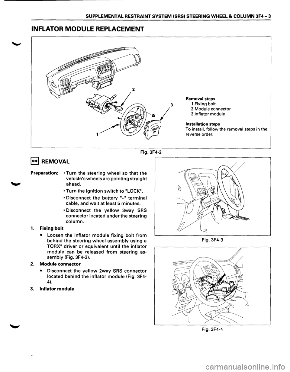
Fig. 3F4-2
B REMOVAL
Preparation: • Turn the steering wheel so that the
vehicle's wheels are pointing straight
._,. ahead.
1. Fixing bolt
• Turn the ignition switch to "LOCK".
•
Disconnect the battery "-" terminal
cable,
and wait at least 5 minutes.
• Disconnect the yellow 3way SRS
connector located under the steering
column.
•
Loosen the inflator module fixing bolt from
behind the steering wheel assembly using a
TORX<~> driver or equivalent until the inflator
module
can be released from steering as
sembly (Fig. 3F4-3).
2. Module connector
• Disconnect the yellow 2way SRS connector
located behind the inflator module (Fig. 3F4-
4).
3. Inflator module
Removal steps
3 1.Fixing bolt
2.Module connector
3.1nflator module
Installation steps
To install, follow the removal steps in the
reverse order.
Fig. 3F4-3
Fig. 3F4-4
Page 214 of 1928
![ISUZU TROOPER 1995 Owners Guide 3F4-4 SUPPLEMENTAL RESTRAINT SYSTEM (SRS) STEERING WHEEL & COLUMN
(b!] INSPECTION AND REPAIR
\f WARNING
THE INFLATOR MODULE SHOULD ALWAYS BE
CARRIED WITH THE URETHANE COVER AWAY
FROM YOUR BODY](/img/61/57183/w960_57183-213.png "ISUZU TROOPER 1995 Owners Guide 3F4-4 SUPPLEMENTAL RESTRAINT SYSTEM (SRS) STEERING WHEEL & COLUMN
(b!] INSPECTION AND REPAIR
\f WARNING
THE INFLATOR MODULE SHOULD ALWAYS BE
CARRIED WITH THE URETHANE COVER AWAY
FROM YOUR BODY")
3F4-4 SUPPLEMENTAL RESTRAINT SYSTEM (SRS) STEERING WHEEL & COLUMN
(b!] INSPECTION AND REPAIR
\f' WARNING
THE INFLATOR MODULE SHOULD ALWAYS BE
CARRIED WITH THE URETHANE COVER AWAY
FROM YOUR BODY AND SHOULD ALWAYS BE
LAID ON A FLAT SURFACE WITH THE URE
THANE SIDE UP. THIS IS NECESSARY BE
CAUSE A FREE SPACE IS PROVIDED TO ALLOW
THE AIR CUSHION TO EXPAND IN THE UN
LIKELYEVENT OF ACCIDENTAL DEPLOYMENT.
OTHERWISE, PERSONAL INJURY
MAY RESULT
(FIG. 3F4-5).
Fig. 3F4-5
The
Inflator module consists of a cover, air bag,
inflator, and retainer.
Inspect the Inflator module
mainly for the following:
1) Check for holes, cracks, severe blemishes and
deformation on the cover.
2) Check that the retainer is not deformed.
3) Check for defects such as damage and breakage in
the lead
wire ofthe squib.
If an abnormality is found as the result of the in
spection, replace the
Inflator module with a new one.
l·u·IINSTALLATION
3. Inflator module
2. Module connector
• Support the module and carefully connectthe
module connector.
NOTE:
Pass the lead wire through the tabs on the plastic
cover (wire protector)
of inflator to prevent lead
wire
from being pinched.
1. Fixing bolt
• Secure the module with one bolt to relieve
weight on the connector wire.
• Tighten bolts to specified sequence as figure
(Fig. 3F4-6).
Torque
N·m(lb·in.) 8 (69)
• Connect the yellow 3way SRS connector
located under the steering column.
• Connect the battery .. _. terminal cable.
• Set ignition to "ON" while watching warning light.
Light should flash 7 times and then go off.
If lamp
does
not operate correctly, refer to Section 9J.
Fig. 3F4-6
STEERING WHEEL REPLACEMENT
\f' CAUTION:
Once the steering column is removed from the
vehicle, the
column is extremely susceptible to
damage. Dropping the column assembly on its
end
could collapse the steering shaft or loosen
the
slide block which maintains column rigidity.
Leaning on the column assembly could cause the
jacket
to bend or deform. Any of the above
damage could
impair the column's collapsible
design. If it is necessary to remove the steering
wheel, use
only the specified steering wheel
puller.
Under no conditions should the end of the
shaft be hammered upon,
as hammering could
loosen
slide block which maintains column
rigidity.
•
Page 215 of 1928
SUPPLEMENTAL RESTRAINT SYSTEM (SRS) STEERING WHEEL & COLUMN 3F4-5
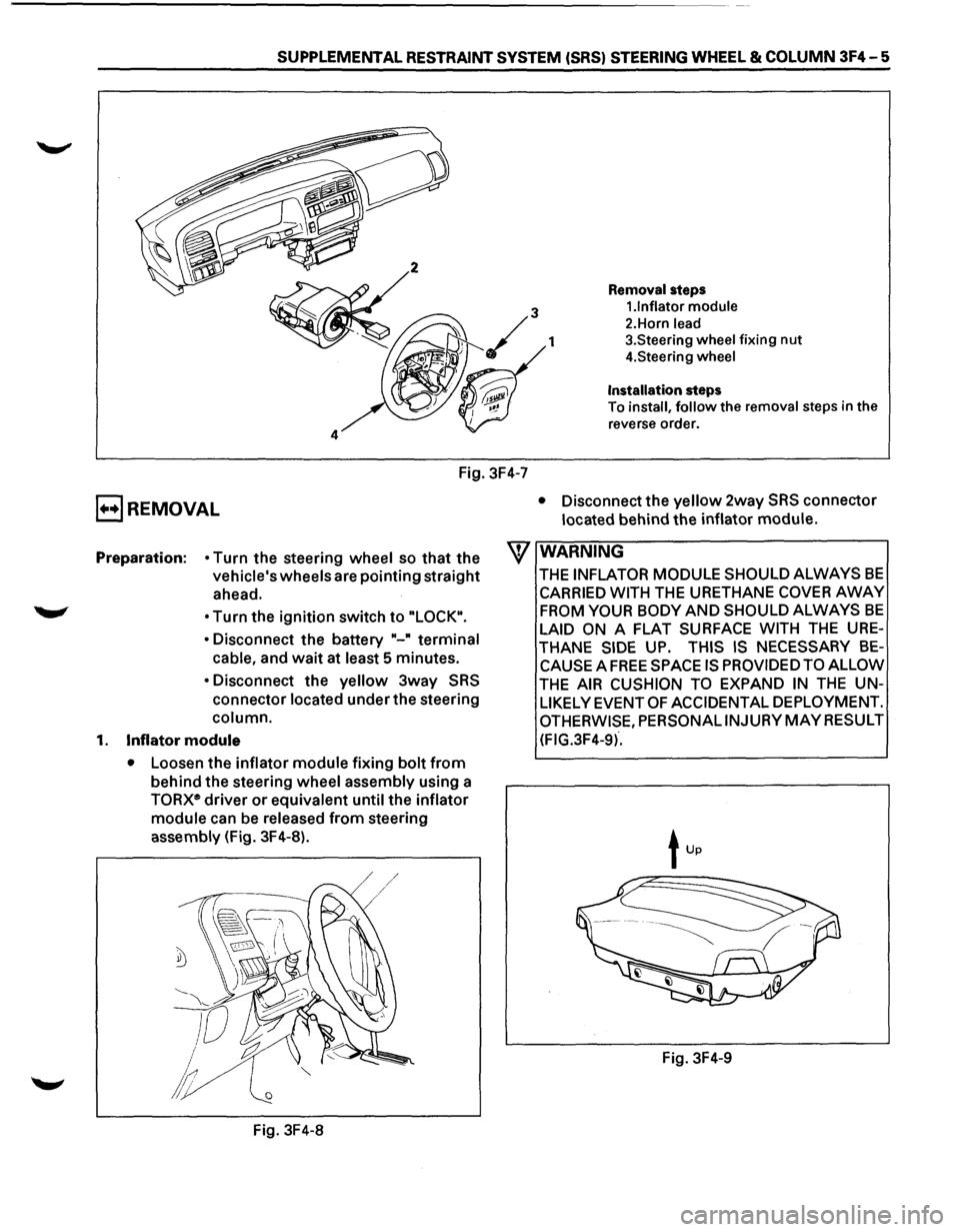
Removal steps
1.1nflator module
2.Horn lead
1 3.Steering wheel fixing nut
4.Steering wheel
Installation steps
To
install, follow the removal steps in the
reverse order.
Fig. 3F4-7
E) REMOVAL
Preparation: • Turn the steering wheel so that the
vehicle's wheels are
pointing straight
ahead.
• Turn the ignition switch to "LOCK".
•
Disconnect the battery "-• terminal
cable, and
wait at least 5 minutes.
• Disconnect the yellow 3way SRS
connector located under the steering
column.
1. Inflator module
• Loosen the inflator module fixing bolt from
behind the steering wheel assembly using a
TORXe driver or equivalent until the inflator
module can be released from steering
assembly (Fig. 3F4-8).
Fig. 3F4-8
• Disconnect the yellow 2way SRS connector
located behind
the inflator module.
W WARNING
THE INFLATOR MODULE SHOULD ALWAYS BE
CARRIED WITH THE URETHANE COVER AWAY
FROM YOUR BODY AND SHOULD ALWAYS BE
LAID ON A FLAT SURFACE WITH THE URE
THANE SIDE UP. THIS IS NECESSARY BE
CAUSE A FREE SPACE IS PROVIDED TO ALLOW
THE AIR CUSHION TO EXPAND IN THE UN
LIKELY EVENT
OF ACCIDENTAL DEPLOYMENT.
OTHERWISE, PERSONAL INJURY MAY RESULT
(FIG.3F4-9l".
Fig. 3F4-9
Page 216 of 1928
3F4-6 SUPPLEMENTAL RESTRAINT SYSTEM ISRSI STEERING WHEEL & COLUMN
2. Horn lead
3. Steering wheel fixing nut
4. Steering wheel
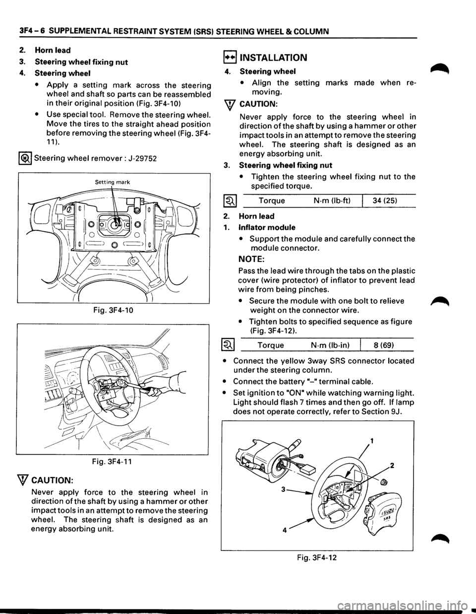
• Apply a setting mark across the steering
wheel and shaft so parts can be reassembled
in
their original position (Fig. 3F4-10)
•
Use special tool. Remove the steering wheel.
Move the tires to the straight ahead position
before removing
the steering wheel (Fig. 3F4-
11 ).
1®.1 Steering wheel remover: J-29752
Setting mark
Fig. 3F4-10
Fig. 3F4-11
"fCAUTION:
Never apply force to the steering wheel in
direction
ofthe shaft by using a hammer or other
impacttools in an attemptto remove the steering
wheel. The steering shaft is designed as an
energy absorbing unit.
B INSTALLATION
4. Steering wheel
• Align the setting marks made when re
moving.
"f CAUTION:
3.
~
2.
1.
~
Never apply force to the steering wheel in
direction
of the shaft by using a hammer or other
impacttools in an attemptto remove the steering
wheel. The steering shaft is designed as an
energy absorbing unit.
Steering wheel fixing nut
• Tighten the steering wheel fixing nut to the
specified torque.
Torque
N-m (lb·ft) 34 (25)
Horn
lead
Inflator module
• Support the module and carefully connect the
module connector.
NOTE:
Pass the lead wire through the tabs on the plastic
cover (wire protector) of inflator to prevent lead
wire from being pinches.
• Secure the module with one bolt to relieve
weight on the connector wire.
• Tighten bolts to specified sequence as figure
(Fig. 3F4-12).
Torque
N·m (lb-in) 8 (69)
• Connect the yellow 3way SRS connector located
under the steering column.
• Connect the battery"-" terminal cable.
• Set ignition to "ON• while watching warning light.
Light
should flash 7 times and then go off. If lamp
does not operate correctly, refer to Section 9J.
Fig. 3F4-12
~
•
Page 217 of 1928
SUPPLEMENTAL RESTRAINT SYSTEM (SRS) STEERING WHEEL & COLUMN 3F4-7
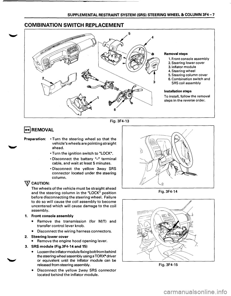
COMBINATION SWITCH REPLACEMENT
Fig. 3F4-13
E) REMOVAL
Preparation: • Turn the steering wheel so that the
vehicle's wheels are pointing straight
ahead.
W CAUTION: •
Turn the ignition switch to "LOCK".
•
Disconnect the battery "-" terminal
cable, and wait at least 5 minutes.
• Disconnect the yellow 3way SRS
connector located under the steering
column.
The wheels ofthe vehicle must be straight ahead
and
the steering column in the "LOCK" position
before disconnecting the steering wheel. Failure
to do so will cause the coil assembly to become
uncentered
which will cause damage to the coil
assembly.
1.
Front console assembly
•
Remove the transmission (for M{f) and
transfer control lever knob.
• Disconnect the wiring harness connectors.
2. Steering lower cover
• Remove the engine hood opening lever.
3. SRS module (Fig.3F4-14 and 15)
• Loosen the inflator module fixing bolt from behind
the steering
wheel assembly using a TORxe driver
or
equivalent until the inflator module can be
released from steering assembly.
•
Disconnect the yellow 2way SRS connector
located behind the inflator module.
3
Removal steps
1. Front console assembly
2. Steering lower cover
3.1nflator module
4. Steering wheel
5. Steering column cover
6. Combination switch and
SRS coil assembly
Installation steps
To install, follow the removal
steps in the reverse order.
Fig. 3F4-14
Fig. 3F4-15
Page 219 of 1928
SUPPLEMENTAL RESTRAINT SYSTEM (SRS) STEERING WHEEL & COLUMN 3F4-9
B INSTALLATION
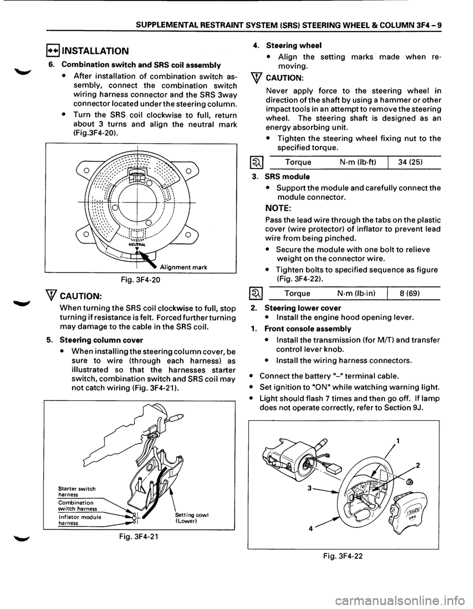
6. Combination switch and SRS coil assembly
•
After installation of combination switch as
sembly, connect the combination switch
wiring harness connector and the SRS 3way
connector located under the steering column.
•
Turn the SRS coil clockwise to full, return
about 3
turns and align the neutral mark
(Fig.3F4-20).
Alignment mark
Fig. 3F4-20
WcAUTION:
When turning the SRS coil clockwise to full, stop
turning if resistance is felt. Forced further turning
may damage to the cable in the SRS coil.
5. Steering column cover
• When installing the steering column cover, be
sure
to wire (through each harness) as
illustrated so that the harnesses starter
switch,
combination switch and SRS coil may
not catch wiring (Fig. 3F4-21 ).
Starter switch
harness
Combination switch harness
Inflator module harness
Fig. 3F4-21
4. Steering wheel
• Align the setting marks made when re
moving.
W CAUTION:
Never apply force to the steering wheel in
direction
of the shaft by using a hammer or other
impact tools in an attempt to remove the steering
wheel. The steering shaft is designed as an
energy absorbing unit.
• Tighten the steering wheel fixing nut to the
specified torque.
Torque
N·m (lb-ft) 34 (25)
3. SRS module
• Support the module and carefully connect the
module connector.
NOTE:
Pass the lead wire through the tabs on the plastic
cover (wire protector) of inflator to prevent lead
wire from being pinched.
• Secure the module with one bolt to relieve
weight on the connector wire.
• Tighten bolts to specified sequence as figure
(Fig. 3F4-22).
Torque
N·m (lb·in) 8 (69)
2. Steering lower cover
• Install the engine hood opening lever.
1. Front console assembly
• Install
the transmission (for MfT) and transfer
control lever knob.
• Install the wiring harness connectors.
• Connect the battery "-"terminal cable.
• Set
ignition to ·oN" while watching warning light.
•
Light should flash 7 times and then go off. If lamp
does not operate correctly, refer to Section 9J.
Fig. 3F4-22
Page 220 of 1928
3F4-10 SUPPLEMENTAL RESTRAINT SYSTEM (SRS) STEERING WHEEL & COLUMN
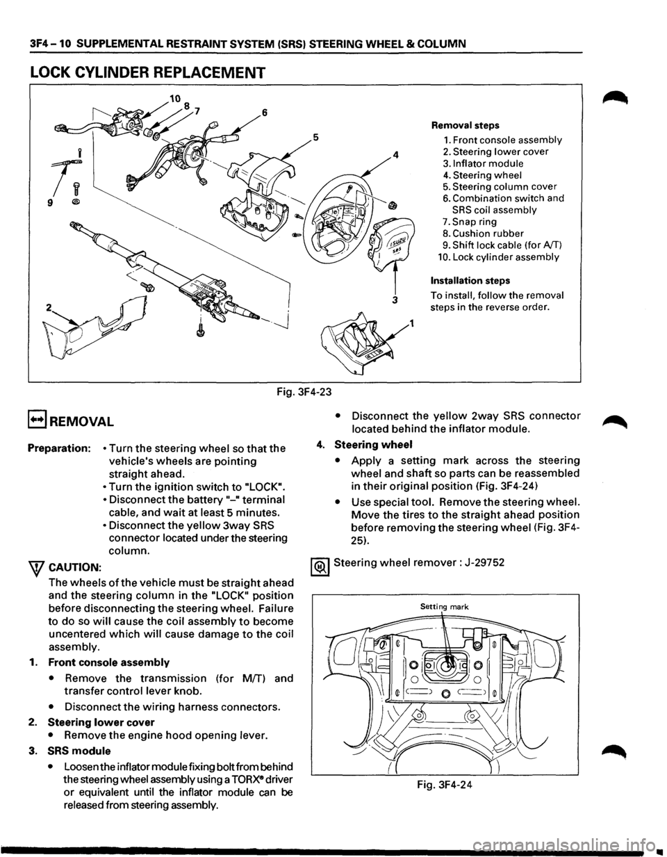
LOCK CYLINDER REPLACEMENT
5
i
;;
9 ®
Fig. 3F4-23
E) REMOVAL
4
3
1
Removal steps
1. Front console assembly
2. Steering lower cover
3.1nflator module
4. Steering wheel
5. Steering column cover
6. Combination switch and
SRS coil assembly
7. Snap ring
8. Cushion rubber
9. Shift lock cable (for AfT)
10. Lock cylinder assembly
Installation steps
To install, follow the removal
steps in the reverse order.
• Disconnect the yellow 2way SRS connector
located behind the inflator module.
Preparation:
• Turn the steering wheel so that the
vehicle's wheels are
pointing
straight ahead.
4. Steering wheel
• Turn the ignition switch to "LOCK".
•
Disconnect the battery"-" terminal
cable, and wait at least 5 minutes.
• Disconnect the yellow 3way SRS
connector located under the steering
column.
• Apply a setting mark across the steering
wheel and
shaft so parts can be reassembled
in
their original position (Fig. 3F4-24)
• Use special tool. Remove the steering wheel.
Move the tires to the straight ahead position
before removing the steering wheel (Fig. 3F4-
25).
W CAUTION: 1®.1 Steering wheel remover: J-29752
The wheels
of the vehicle must be straight ahead
and the steering
column in the "LOCK" position
before disconnecting the steering wheel. Failure
Setting mark
to do so will cause the coil assembly to become
uncentered
which will cause damage to the coil
assembly.
1.
Front console assembly
• Remove the transmission (for Mff) and
transfer
control lever knob.
• Disconnect the wiring harness connectors.
2. Steering lower cover
• Remove the engine hood opening lever.
3. SRS module
• Loosen the inflator module fixing bolt from behind
the steering wheel assembly using a
TORXe driver
or equivalent until the inflator module can be
released from steering assembly. Fig.
3F4-24
•
Page 222 of 1928
3F4 -12 SUPPLEMENTAL RESTRAINT SYSTEM (SRS) STEERING WHEEL & COLUMN
Alignment mark
Fig. 3F4-28
\fCAUTION:
When turning the SRS coil clockwise to full, stop
turning if resistance is felt. Forced further turning
may damage to the cable in the SRS coil.
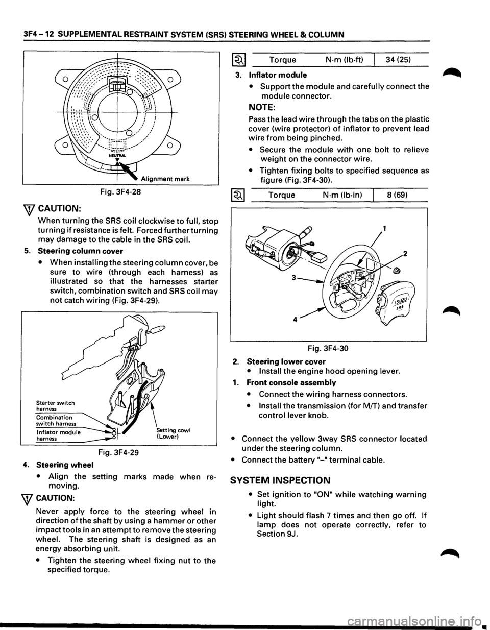
5. Steering column cover
• When installing the steering column cover, be
sure
to wire (through each harness) as
illustrated so that the harnesses starter
switch,
combination switch and SRS coil may
not catch wiring (Fig. 3F4-29).
Starter switch
harness
Combination
switch harness
Inflator module
harness
4. Steering wheel
Fig. 3F4-29
• Align the setting marks made when re
moving.
\fCAUTION:
Never apply force to the steering wheel in
direction
of the shaft by using a hammer or other
impacttools in an attemptto remove the steering
wheel. The steering shaft is designed as an
energy absorbing unit.
• Tighten the steering wheel fixing nut to the
specified torque.
~~~ Torque N·m (lb-ft) 34 (25)
3. Inflator module
• Support the module and carefully connect the
module connector.
NOTE:
Pass the lead wire through the tabs on the plastic
cover (wire protector) of inflator to prevent lead
wire from being pinched.
• Secure the module with one bolt to relieve
weight on the connector wire.
• Tighten fixing bolts to specified sequence as
figure (Fig. 3F4-30).
1~1 Torque N·m (lb-in) 8 (69)
Fig.
3F4-30
2. Steering lower cover
• Install the engine hood opening lever.
1. Front console assembly
• Connect the wiring harness connectors.
• Install the transmission (for Mff) and transfer
control lever knob.
• Connect the yellow 3way SRS connector located
under the steering column.
• Connect the battery"-" terminal cable.
SYSTEM INSPECTION
• Set ignition to "ON" while watching warning
light.
•
Light should flash 7 times and then go off. If
lamp does not operate correctly, refer to
Section 9J.
Page 224 of 1928
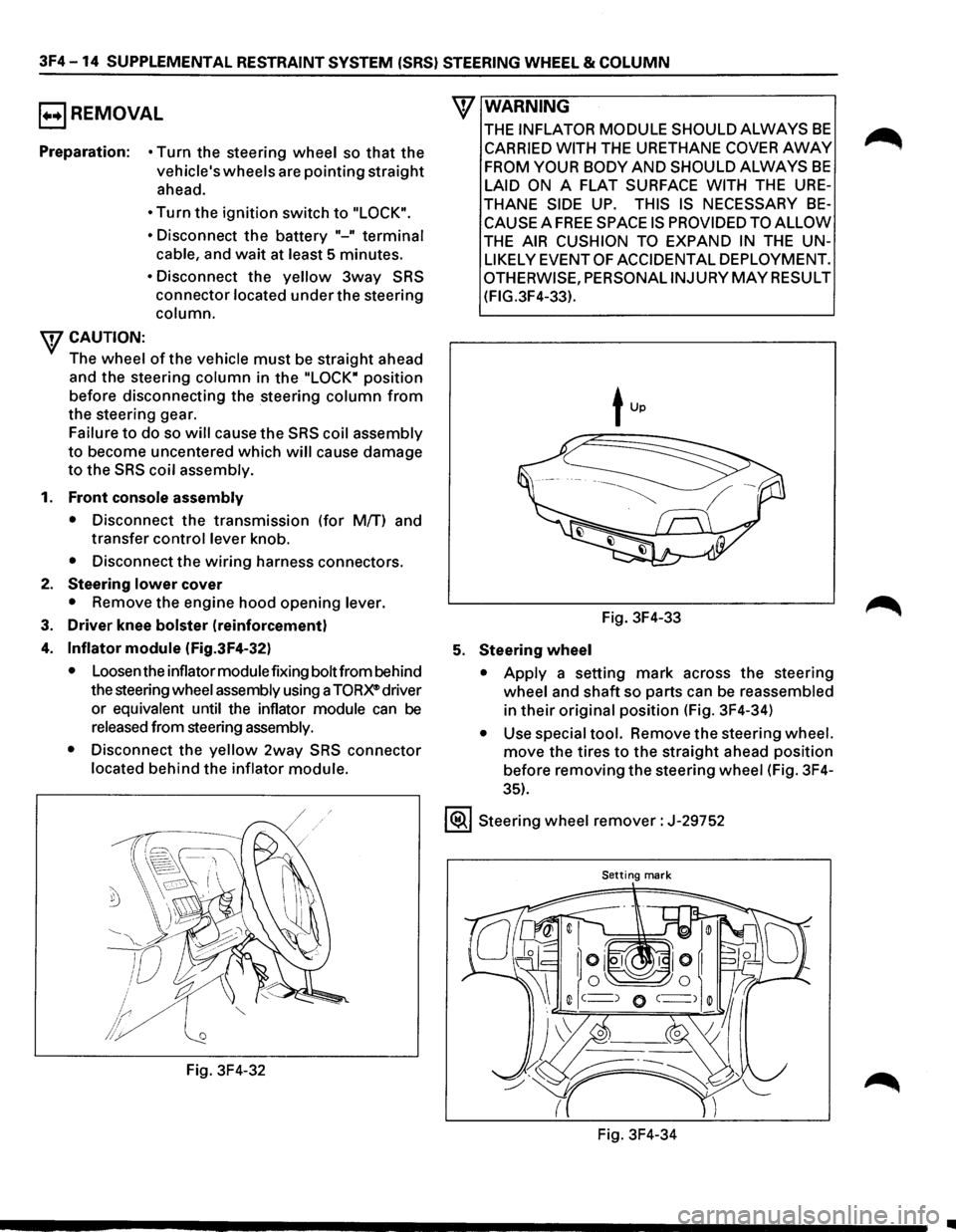
3F4-14 SUPPLEMENTAL RESTRAINT SYSTEM (SRS) STEERING WHEEL & COLUMN
EJREMOVAL
Preparation: • Turn the steering wheel so that the
vehicle's
wheels are pointing straight
ahead.
• Turn the ignition switch to "LOCK".
•
Disconnect the battery "-" terminal
cable,
and wait at least 5 minutes.
• Disconnect the yellow 3way SRS
connector located under the steering
column.
wcAUTION:
The wheel of the vehicle must be straight ahead
and the steering
column in the "LOCK• position
before disconnecting the steering
column from
the steering gear.
Failure to do so will cause the SRS coil assembly
to become uncentered which will cause damage
to the SRS coil assembly.
1. Front console assembly
• Disconnect the transmission (for MfT) and
transfer
control lever knob.
• Disconnect the wiring harness connectors.
2. Steering lower cover
• Remove the engine hood opening lever.
3. Driver knee bolster (reinforcement)
4. Inflator module (Fig.3F4-32)
• Loosen the inflator module fixing bolt from behind
the steering
wheel assembly using a TORX® driver
or
equivalent until the inflator module can be
released from steering assembly.
•
Disconnect the yellow 2way SRS connector
located behind the inflator module.
Fig. 3F4-32
\V WARNING
THE INFLATOR MODULE SHOULD ALWAYS BE
CARRIED WITH THE URETHANE COVER AWAY
FROM YOUR BODY AND SHOULD ALWAYS BE
LAID ON A FLAT SURFACE WITH THE URE
THANE SIDE UP. THIS IS NECESSARY BE
CAUSE A FREE SPACE IS PROVIDED TO ALLOW
THE AIR CUSHION TO EXPAND IN THE UN
LIKELY EVENT OF ACCIDENTAL DEPLOYMENT.
OTHERWISE, PERSONALINJURYMAYRESULT
(FIG.3F4-33).
Fig. 3F4-33
5. Steering wheel
• Apply a setting mark across the steering
wheel and shaft so parts can be reassembled
in their original position (Fig. 3F4-34)
• Use special tool. Remove the steering wheel.
move the tires to the straight ahead position
before removing the steering
wheel (Fig. 3F4-
35).
1®.1 Steering wheel remover: J-29752
Setting mark
Fig. 3F4-34
..