battery ISUZU TROOPER 1995 Repair Manual
[x] Cancel search | Manufacturer: ISUZU, Model Year: 1995, Model line: TROOPER, Model: ISUZU TROOPER 1995Pages: 1928
Page 489 of 1928
ILLUSTRATION
'~ ~··
J -
~
. .
"
~
"f'38~
0
~~ '~
--~ S::S.·f
-~; -~b'
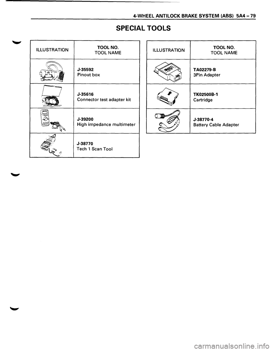
SPECIAL TOOLS
TOOL NO.
TOOL
NAME ILLUSTRATION
J-35592
Pinout box
J-35616
Connector test adapter kit
J-39200
High impedance multimeter
J-38770
Tech 1 Scan Tool
TOOL NO.
TOOL
NAME
TA02279-B
3Pin Adapter
TK02500B-1
Cartridge
J-38770-4 Battery
Cable Adapter
Page 499 of 1928
ENGINE DIAGNOSIS S-1
ENGINE
CONTENTS
Engine General Information . . . . . . . . . . . . . . . . . . . . . . . . . . . . . . . . . . . . . . . . . . . . . . . . . . . . . Section S
General
Engine Mechanical .................................................... Section SA
3.2L VS Engine ............................................................... Section SA1
Engine Cooling . . . . . . . . . . . . . . . . . . . . . . . . . . . . . . . . . . . . . . . . . . . . . . . . . . . . . . . . . . . . . . . . Section S8
Engine Fuel . . . . . . . . . . . . . . . . . . . . . . . . . . . . . . . . . . . . . . . . . . . . . . . . . . . . . . . . . . . . . . . . . . . Section SC
Engine Electrical . . . . . . . . . . . . . . . . . . . . . . . . . . . . . . . . . . . . . . . . . . . . . . . . . . . . . . . . . . . . . . Section SD
Driveability and Emissions . . . . . . . . . . . . . . . . . . . . . . . . . . . . . . . . . . . . . . . . . . . . . . . . . . . . Section SE2
Engine Exhaust . . . . . . . . . . . . . . . . . . . . . . . . . . . . . . . . . . . . . . . . . . . . . . . . . . . . . . . . . . . . . . . Section SF
SECTION 6
ENGINE GENERAL INFORMATION
CONTENTS
Description of Engine Section . . . . . . . . . . . . . . . . . . . . . . . . . . . . . . . . . . . . . . . . . . . . . . . . . . . . . . . . S-1
General Description . . . . . . . . . . . . . . . . . . . . . . . . . . . . . . . . . . . . . . . . . . . . . . . . . . . . . . . . . . . . . . . . . S-2
Engine Diagnosis . . . . . . . . . . . . . . . . . . . . . . . . . . . . . . . . . . . . . . . . . . . . . . . . . . . . . . . . . . . . . . . . . . . . S-2
DESCRIPTION OF ENGINE SECTION
SECTIONS-ENGINE GENERAL INFORMATION SECTION S8-ENGINE COOLING
General description
Engine cleanliness and care, and general information
on engine service are covered in this section.
Engine diagnosis
This section covers the components of the fuel,
ignition, and mechanical systems that could cause a
particular complaint, and then outlines repairs in a
logical sequence.
SECTION SA-ENGINE MECHANICAL
This section contains information on the mechanical
parts of the engine, such as cylinder block, cylinder
head, crankshaft, pistons, valve train, camshaft, and
engine
lubrication.
Overhaul
procedures, removal and replacement
procedures, and specifications are also covered.
Specific subsections are:
SA-GENERAL;
Disassembly and reassembly procedures,
inspection and repair procedures
off the vehicle.
6A 1-3.2L V6 ENGINE;
Removal
and replacement procedures on the
vehicle.
Engine cooling system components such as radiator,
engine
coolant pump, thermostat, and cooling fan, are
covered
in this section.
SECTION SC-ENGINE FUEL
This section contains information on all the parts of the
fuel system except the fuel injectors, or throttle body II
unit itself. Items covered are: fuel tank, fuel pump, fuel
filter,
and fuel lines. Specific sections are used for each
fuel system type:
Port
Injection fuel rail and injectors will be found in
Section
6E2.
SECTION SD-ENGINE ELECTRICAL
Items covered in this section are battery, generator,
starter, ignition
coil, spark plugs and wires.
Ignition system diagnosis will be found in Section 6E2
as a "C4" chart.
Specific sections are:
601 -Battery
602 - Cranking System
603 -Charging System
604 -Ignition System
Page 500 of 1928
6-2 ENGINE DIAGNOSIS
SECTION 6E-DRIVEABILITY
AND EMISSIONS
This section covers emission control systems general
information, and diagnostic procedures which will lead
to repairing performance and driveability related
problems.
Emission components are covered, as well
as removal and replacement procedures.
Instructions on use
of special tools are also given.
SECTION 6F-ENGINE EXHAUST
This section has information on all exhaust system
parts, such
as tailpipes, mufflers, and the catalytic
converter.
GENERAL DESCRIPTION
ENGINE CLEANLINESS AND CARE
An automobile engine is a combination of many
machined, honed,
polished and lapped surfaces with
tolerances that are measured in the thousandths of a
millimeter (ten thousandths of an inch). Accordingly,
when any
internal engine parts are serviced, care and
cleanliness are important. Throughout this section, it
should be understood that proper cleaning and
protection
of machined surfaces and friction areas is
part
of the repair procedure. This is considered
standard shop practice even
if not specifically stated.
• A liberal coating of engine oil should be applied to
all friction areas during assembly to protect and
lubricate the surfaces on initial operation.
• Whenever valve train components, pistons, piston
rings, connecting rods, rod bearings, and
crankshaft
journal bearings are removed for
service, they should be retained in order.
• At the time of installation, they should be installed
in the same locations and with the same mating
surfaces
as when removed.
• Battery cables should be disconnected before any
major
work is performed on the engine. Failure to
disconnect
cables may result in damage to wire
harness
or other electrical parts.
• The six cylinders of this engine are identified by
numbers; Right side
cylinders 1, 3 and 5, Left side
cylinders 2, 4 and 6, as counted from crankshaft
pulley side to flywheel side.
GENERAL INFORMATION ON ENGINE
SERVICE
The following information on engine service should be
noted
carefully, as it is important in preventing damage
and contributing
to reliable engine performance.
• When raising or supporting the engine for any
reason,
do not use a jack under the oil pan. Due to
the
small clearance between the oil pan and the oil
pump strainer, jacking against the oil pan may
cause damage to the
oil pick-up unit.
• The 12-volt electrical system is capable of
damaging circuits. When performing any work
where electrical terminals could possibly be
grounded, the ground cable of the battery should
be disconnected at the battery.
• Any time the intake air duct or air cleaner is
removed, the intake opening
should be covered.
This
will protect against accidental entrance of
foreign material into the cylinder which could
cause extensive damage when the engine is
started.
ENGINE DIAGNOSIS
CONTENTS
Hard Starting . . . . . . . . . . . . . . . . . . . . . . . . . 6-3
Engine Compression
Test Procedure ..... 6-4
Rough Engine
Idling or Engine Stalling . . . 6-5
Rough Engine Running . . . . . . . . . . . . . . . . .
6-6
Hesitation . . . . . . . . . . . . . . . . . . . . . . . . . . . . 6-7
Engine Lacks
Power . . . . . . . . . . . . . . . . . . . . 6-8
Engine
Noisy .......................... 6-10
Abnormal Combustion . . . . . . . . . . . . . . . . . . 6-12
Engine Oil Consumption Excessive . . . . . . . 6-13
Fuel Consumption Excessive ............. 6-14
Oil Problems . . . . . . . . . . . . . . . . . . . . . . . . . . 6-14
Malfunction Indicator Lamp . . . . . . . . . . . . . . 6-15
Engine Oil Pressure Check ............... 6-16
Inspection of Hydraulic Lash Adjuster . . . . . 6-17
Page 501 of 1928
ENGINE DIAGNOSIS 6-3
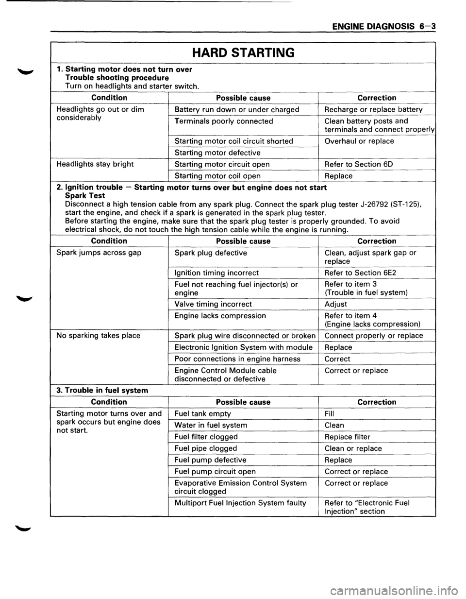
HARD STARTING
1. Starting motor does not turn over
Trouble shooting procedure
Turn on headlights and starter switch.
Condition Possible cause Correction
Headlights go out or dim Battery run down or under charged Recharge or replace battery
considerably
Terminals poorly connected Clean battery posts and
terminals and connect properly
Starting motor coil circuit shorted Overhaul or replace
Starting motor defective
Headlights stay
bright Starting motor circuit open Refer to Section 6D
Starting
motor coil open Replace
2. Ignition trouble -Starting motor turns over but engine does not start
Spark Test
Disconnect a high tension cable from any spark plug. Connect the spark plug tester J-26792 (ST-1 25).
start the engine, and check if a spark is generated in the spark plug tester.
Before starting the engine, make sure
that the spark plug tester is properly grounded. To avoid
electrical shock, do not touch the high tension cable while the engine is running.
Condition Possible cause Correction
Spark jumps across gap
Spark plug defective Clean, adjust spark gap or
replace
Ignition
timing incorrect Refer to Section 6E2
Fuel not reaching fuel injector(s) or Refer to item 3
engine (Trouble
in
fuel system)
Valve
timing incorrect Adjust
Engine
lacks compression Refer to item 4
(Engine
lacks compression)
No sparking takes
place Spark plug wire disconnected or broken Connect properly or replace
Electronic Ignition System with module Replace
Poor connections in engine harness
Correct
Engine Control
Module cable Correct or replace
disconnected or defective
3. Trouble in fuel system
Condition Possible cause Correction
Starting motor turns over and
Fuel tank empty Fill
spark occurs but engine does
not start. Water in fuel system Clean
Fuel filter clogged Replace filter
Fuel pipe clogged Clean or replace
Fuel pump defective
Replace
Fuel
pump circuit open Correct or replace
Evaporative Emission Control System Correct or replace
circuit clogged
Multipart Fuel Injection System faulty Refer to "Electronic Fuel
Injection"
section
Page 562 of 1928
6A1-4 ENGINE (V6 3.2L DOHC AND SOHC)
ON-VEHICLE SERVICE
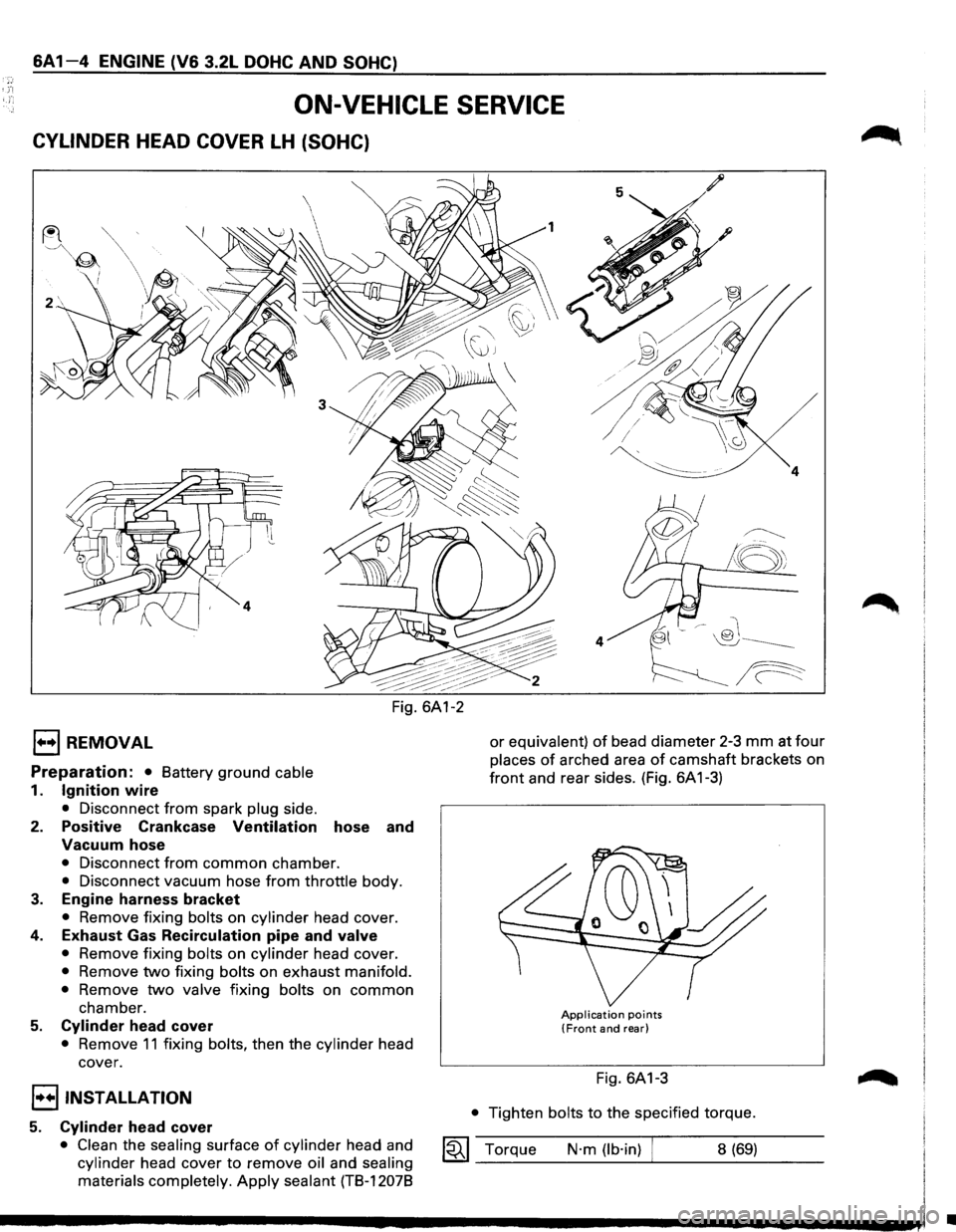
CYLINDER HEAD COVER LH (SOHC)
1••1 REMOVAL
Preparation: • Battery ground cable
1. Ignition wire
• Disconnect from spark plug side.
2. Positive Crankcase Ventilation hose and
Vacuum hose
• Disconnect from common chamber.
• Disconnect vacuum hose from throttle body.
3. Engine harness bracket
• Remove fixing bolts on cylinder head cover.
4. Exhaust Gas Recirculation pipe and valve
• Remove fixing bolts on cylinder head cover.
• Remove two fixing bolts on exhaust manifold.
•
Remove two valve fixing bolts on common
chamber.
5. Cylinder head cover
• Remove 11 fixing bolts, then the cylinder head
cover.
I••IINST ALLA TION
5. Cylinder head cover
• Clean the sealing surface of cylinder head and
cylinder head cover to remove oil and sealing
materials completely.
Apply sealant (TB-12078
/
~
!8;
4
or equivalent) of bead diameter 2-3 mm at four
places of arched area of camshaft brackets on
front and rear sides. (Fig. 6A 1-3)
Application points (Front and rear)
Fig. 6A1-3
• Tighten bolts to the specified torque.
1~1 Torque N·m (lb·in) 8 (69)
•
Page 563 of 1928
4. Exhaust Gas Recirculation pipe and valve
• Tighten each fixing bolt to the specified torque.
Valve fixing bolt
1«1 Torque N·m (lb·in) 8 (69)
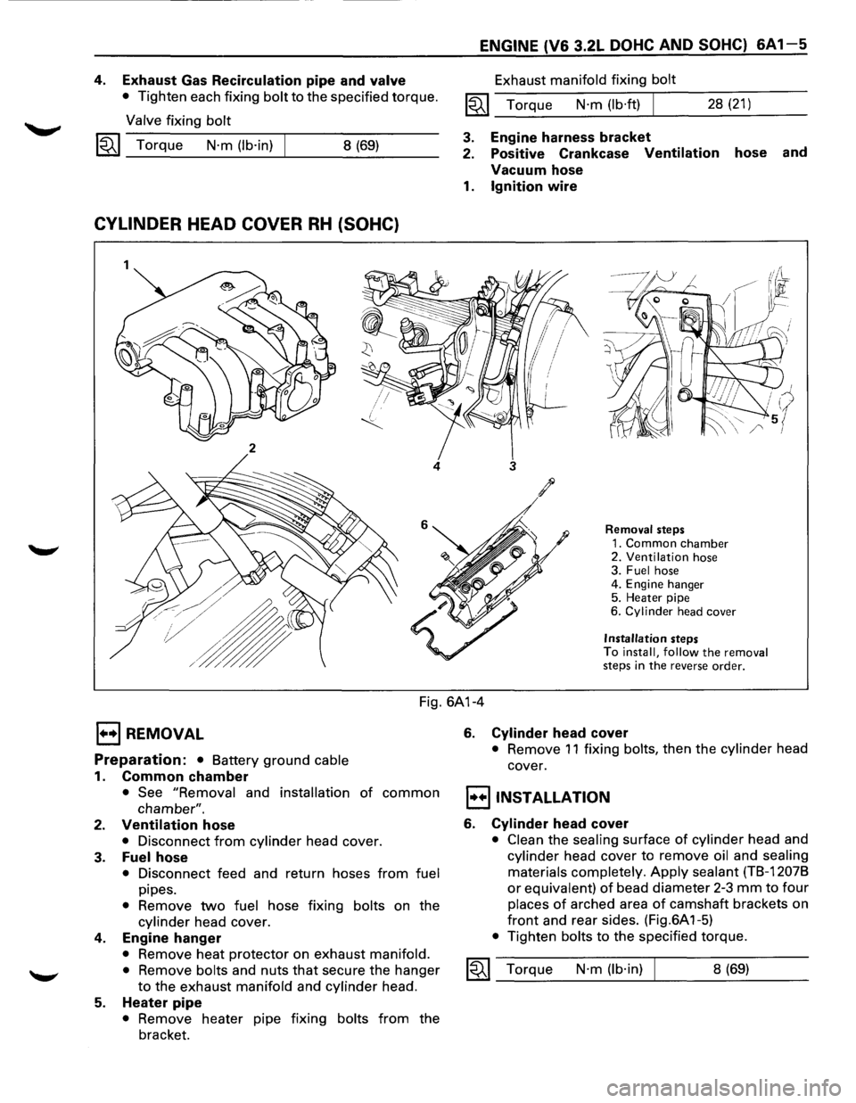
CYLINDER HEAD COVER RH (SOHC)
1
2
4
ENGINE (V6 3.2L DOHC AND SOHC) 6A1-5
Exhaust manifold fixing bolt
1«1 Torque N·m (lb·ft) I 28 (21)
3. Engine harness bracket
2. Positive Crankcase
Ventilation hose and
Vacuum hose
1. Ignition wire
3
Removal steps
1. Common chamber 2. Ventilation hose
3. Fuel hose
4. Engine hanger
5. Heater pipe
6.
Cylinder head cover
Installation steps
To install, follow the removal
steps in the reverse order.
Fig. 6A1-4
EJ REMOVAL
Preparation: • Battery ground cable
1. Common chamber
• See "Removal and installation of common
chamber".
2. Ventilation hose
• Disconnect from cylinder head cover.
3. Fuel hose
• Disconnect feed and return hoses from fuel
pipes.
• Remove two fuel hose fixing bolts on the
cylinder head cover.
4. Engine hanger
• Remove heat protector on exhaust manifold.
•
Remove bolts and nuts that secure the hanger
to the exhaust manifold and cylinder head.
5. Heater pipe
• Remove heater pipe fixing bolts from the
bracket.
6. Cylinder head cover
• Remove 11 fixing bolts, then the cylinder head
cover.
I•+IINSTALLATION
6. Cylinder head cover
• Clean the sealing surface of cylinder head and
cylinder head cover to remove oil and sealing
materials completely.
Apply sealant (TB-12078
or equivalent) of bead diameter 2-3 mm to four
places of arched area of camshaft brackets on
front and rear sides. (Fig.6A 1-5)
• Tighten bolts to the specified torque.
1«1 Torque N·m (lb·in) 8 (69)
Page 565 of 1928
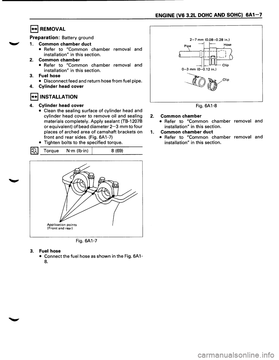
E) REMOVAL
Preparation: Battery ground
1. Common chamber duct
• Refer to "Common chamber removal and
installation" in this section.
2. Common chamber
• Refer to "Common chamber removal and
installation" in this section.
3. Fuel hose
• Disconnect feed and return hose from fuel pipe.
4. Cylinder head cover
I••IINSTALLATION
4. Cylinder head cover
• Clean the sealing surface of cylinder head and
cylinder head cover to remove oil and sealing
materials completely.
Apply sealant (TB-12078
or equivalent) of bead diameter 2-3 mm to four
places of arched area of camshaft brackets on
front and rear sides. (Fig. 6A 1-7)
• Tighten bolts to the specified torque.
1«1 Torque N·m (lb·in) 8 (69)
Application points (Front and rear)
Fig. 6A1-7
3. Fuel hose
• Connect the fuel hose as shown in the Fig. 6A 1-
8.
ENGINE (V6 3.2L DOHC AND SOHC) 6A 1-7
2-7 mm (0.08-0.28 in.)
r-
0-3 mm (0-0.12 in.)
·~(t)yCIIp
Fig. 6A1-8
2. Common chamber
• Refer to "Common chamber removal and
installation" in this section.
1. Common chamber duct
• Refer to "Common chamber removal and
installation" in this section.
Page 566 of 1928
6A1-8 ENGINE (V6 3.2L DOHC AND SOHC)
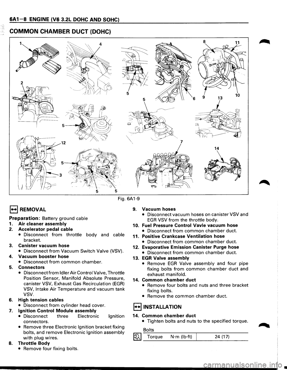
COMMON CHAMBER DUCT (DOHC)
8
11
5
5
6
7
14
5 5
Fig. 6A1-9
E) REMOVAL
Preparation: Battery ground cable
1. Air cleaner assembly
2. Accelerator pedal cable
• Disconnect from throttle body and cable
bracket.
3. Canister vacuum hose
• Disconnect from Vacuum Switch Valve (VSV).
4. Vacuum booster hose
• Disconnect from common chamber.
5. Connectors
• Disconnect from Idler Air Control Valve, Throttle
Position Sensor, Manifold Absolute Pressure,
canister VSV, Exhaust Gas Recirculation (EGR)
VSV, Intake Air Temperature and vacuum tank
vsv.
6. High tension cables
• Disconnect from cylinder head cover.
7. Ignition Control Module assembly
• Disconnect three Electronic Ignition
connectors.
• Remove three Electronic Ignition bracket fixing
bolts, and remove Electronic Ignition assembly
with plug wires.
8. Throttle Body
• Remove four fixing bolts.
9. Vacuum hoses
• Disconnect vacuum hoses on canister VSV and
EGR VSV from the throttle body.
10. Fuel Pressure Control Vavle vacuum hose
• Disconnect from common chamber duct.
11. Positive Crankcase Ventilation hose
• Disconnect from common chamber duct.
12. Evaporative Emission Canister Purge hose
• Disconnect from common chamber duct.
13. EGR Valve assembly
• Remove EGR Valve assembly and four pipe
fixing bolts from common chamber duct and
exhaust manifold.
14. Common chamber duct
• Remove four bolts and nuts and three bracket
fixing bolts.
• Remove the common chamber duct.
l·u·IINSTALLATION
14. Common chamber duct
• Tighten bolts and nuts to the specified torque.
Bolts
~~~ Torque N·m (lb·ft) 24 (17)
•
Page 568 of 1928
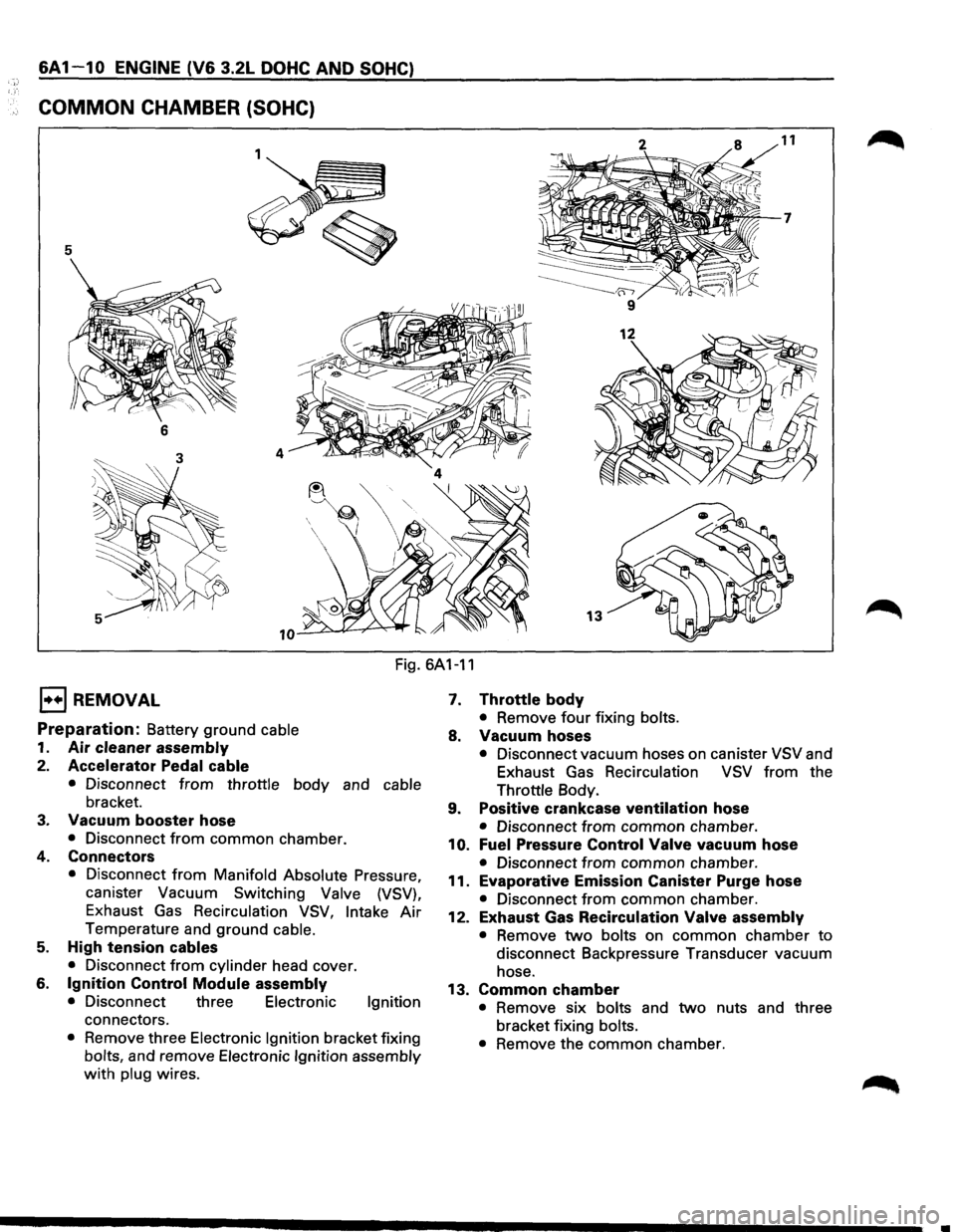
6A 1 1 0 ENGINE (V6 3.2L DOHC AND SOHC)
COMMON CHAMBER (SOHC)
5
6
13
Fig. 6A1-11
1••1 REMOVAL
Preparation: Battery ground cable
1. Air cleaner assembly
2. Accelerator Pedal cable
• Disconnect from throttle body and cable
bracket.
3. Vacuum booster hose
• Disconnect from common chamber.
4. Connectors
• Disconnect from Manifold Absolute Pressure,
canister Vacuum Switching
Valve (VSV),
Exhaust Gas Recirculation VSV, Intake Air
Temperature and ground cable.
5. High tension cables
• Disconnect from cylinder head cover.
6. Ignition Control Module assembly
• Disconnect three Electronic Ignition
connectors.
• Remove three Electronic Ignition bracket fixing
bolts, and remove Electronic Ignition assembly
with plug wires.
7. Throttle body
• Remove four fixing bolts.
8. Vacuum hoses
• Disconnect vacuum hoses on canister VSV and
Exhaust Gas
Recirculation VSV from the
Throttle Body.
9. Positive crankcase ventilation hose
• Disconnect from common chamber.
10. Fuel Pressure Control Valve vacuum hose
• Disconnect from common chamber.
11. Evaporative Emission Canister Purge hose
• Disconnect from common chamber.
12. Exhaust Gas Recirculation Valve assembly
• Remove two bolts on common chamber to
disconnect Backpressure Transducer vacuum
hose.
13. Common chamber
• Remove six bolts and two nuts and three
bracket fixing
bolts.
•
Remove the common chamber.
Page 570 of 1928
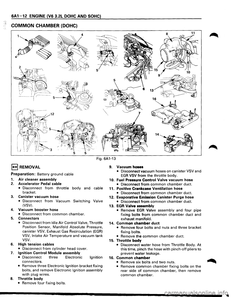
1"!
6A 1-12 ENGINE (V6 3.2L DOHC AND SOHC)
COMMON CHAMBER (DOHC)
Fig. 6A1-13
l•+l REMOVAL
Preparation: Battery ground cable
1. Air cleaner assembly
2. Accelerator Pedal cable
• Disconnect from throttle body and cable
bracket.
3. Canister vacuum hose
• Disconnect from Vacuum Switching Valve
(VSV).
4.
Vacuum booster hose
• Disconnect from common chamber.
5. Connectors
• Disconnect from Idle Air Control Valve, Throttle
Position Sensor, Manifold Absolute Pressure,
canister VSV, Exhaust Gas Recirculation (EGR)
VSV, Intake Air Temperature and vacuum tank
vsv.
6. High tension cables
•
Disconnect from cylinder head cover.
7. Ignition Control Module assembly
• Disconnect three Electronic Ignition
connectors.
• Remove three Electronic Ignition bracket fixing
bolts, and remove Electronic Ignition assembly
with plug wires.
8. Throttle body
• Remove four fixing bolts.
9. Vacuum hoses
• Disconnect vacuum hoses on canister VSV and
EGR VSV from the throttle body.
10. Fuel Pressure Control Valve vacuum hose
• Disconnect from common chamber duct.
11.
Positive Crankcase Ventilation hose
• Disconnect from common chamber duct.
12.
Evaporative Emission Canister Purge hose
• Disconnect from common chamber duct.
13.
EGR Valve assembly
• Remove EGA Valve assembly and four pipe
fixing
bolts from common chamber duct and
exhaust
manifold.
14. Common chamber duct
• Remove four bolts and nuts and three bracket
fixing
bolts.
•
Remove the common chamber duct.
15.
Throttle body
• Disconnect water hose from Throttle Body. At
this time, pinch the hose with pinch-off pliers to
prevent water leakage.
16. Common chamber
• Remove six bolts and two nuts. ~
• Remove common chamber fixing bolts on the
rear side
of common chamber, then remove
common chamber.
1111