clock ISUZU TROOPER 1995 Owner's Guide
[x] Cancel search | Manufacturer: ISUZU, Model Year: 1995, Model line: TROOPER, Model: ISUZU TROOPER 1995Pages: 1928
Page 1219 of 1928
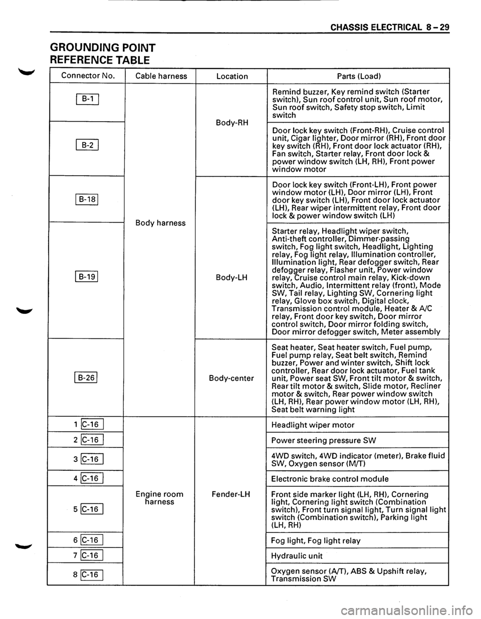
GROUNDING POINT
REFERENCE TABLE
Connector No.
Cable harness
~
~
I B-1a1
Body harness
I B-191
I B-261
1 lc-16 I
2IC-16 I
3IC-16 I
4IC-16 I
Engine room
5IC-16 I
harness
6IC-16 I
7IC-16 I
aiC-16 1
Location
Body-RH
Body-LH
Body-center
Fender-LH
CHASSIS ElECTRICAL 8-29
Parts (Load)
Remind buzzer, Key remind switch (Starter
switch),
Sun roof control unit, Sun roof motor, Sun roof switch, Safety stop switch, Limit
switch
Door lock key switch (Front-RH), Cruise control
unit, Cigar lighter, Door mirror (RH), Front door
key switch (RH), Front door lock actuator (RH),
Fan switch, Starter relay, Front
door lock & power window switch (LH, RH), Front power window motor
Door lock key switch (Front-LH), Front power window motor (LH), Door mirror (LH), Front
door key switch (LH), Front door lock actuator
(LH), Rear wiper intermittent relay, Front door
lock & power window switch (LH)
Starter relay, Headlight
wiper switch,
Anti-theft controller,
Dimmer·passing switch, Fog light switch, Headlight, Lighting
relay, Fog
light relay, Illumination controller,
Illumination light, Rear defogger switch, Rear
defogger relay, Flasher unit,
Power window relay, Cruise control main relay, Kick-down
switch, Audio, Intermittent relay (front), Mode SW, Tail relay, Lighting SW, Cornering light
relay, Glove box switch, Digital clock,
Transmission control module, Heater & A/C
relay, Front
door key switch, Door mirror
control switch, Door mirror folding switch,
Door mirror defogger switch, Meter assembly
Seat heater, Seat heater switch, Fuel pump, Fuel pump relay, Seat belt switch, Remind
buzzer, Power and winter switch, Shift lock
controller, Rear
door lock actuator, Fuel tank
unit, Power seat SW, Front tilt motor & switch,
Rear tilt motor & switch, Slide motor, Recliner
motor & switch, Rear power window switch
(LH, RH), Rear power window motor (LH, RH),
Seat belt warning light
Headlight
wiper motor
Power steering pressure SW
4WD switch, 4WD indicator (meter), Brake fluid
SW, Oxygen sensor (M/T)
Electronic brake control
module
Front side marker light (LH, RH), Cornering
light, Cornering light switch (Combination
switch), Front turn signal light, Turn signal light switch (Combination switch), Parking light (LH, RH)
Fog light, Fog light relay
Hydraulic
unit
Oxygen sensor (AfT), ABS & Upshift relay,
Transmission SW
Page 1235 of 1928
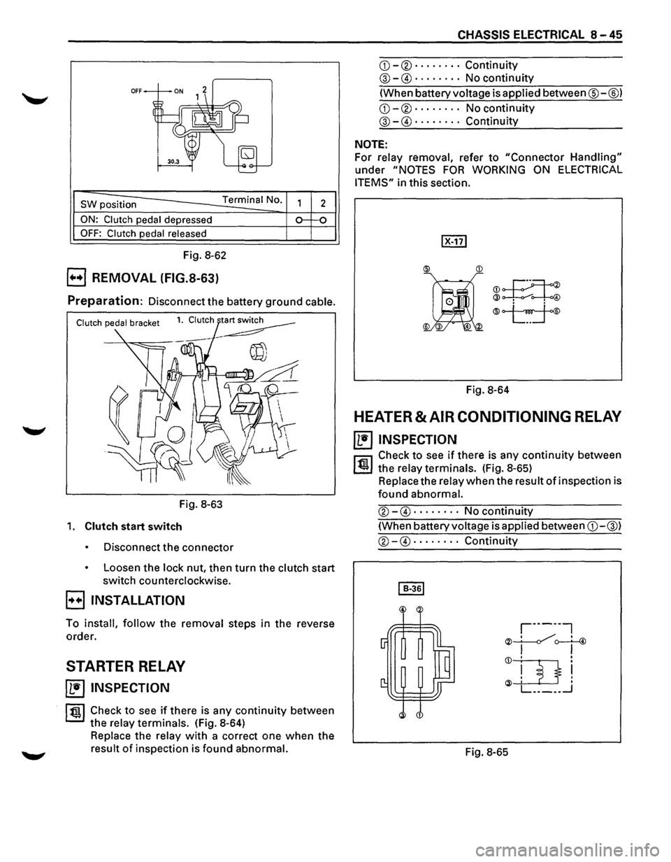
OFF
SW position Terminal No.
ON: Clutch pedal depressed
OFF: Clutch pedal released
Fig. 8-62
B REMOVAL (FIG.S-63)
2
Preparation: Disconnect the battery ground cable.
Fig. 8-63
1. Clutch start switch
Disconnect the connector
Loosen the lock nut, then turn the clutch start
switch counterclockwise.
B INSTALLATION
To install, follow the removal steps in the reverse
order.
STARTER RELAY
~ INSPECTION
ltgl Check to see if there is any continuity between
the relay terminals. (Fig. 8-64)
Replace the relay with a correct one when the
result of inspection is found abnormal.
CHASSIS ELECTRICAL 8-45
CD-®······ · · Continuity
@-G)· . · · · · .. No continuity
(When battery voltage is applied between®-@)
CD-®· · · · · · · · No continuity
@-G)· · · · · · · · Continuity
NOTE:
For relay removal, refer to "Connector Handling"
under "NOTES FOR WORKING ON ELECTRICAL
ITEMS"
in this section.
®JI
@~
®
Fig. 8-64
HEATER & AIR CONDITIONING RELAY
~ INSPECTION
l'fll Check to see if there is any continuity between
~ the relay terminals. (Fig. 8-65)
Replace the relay when the result of inspection is
found abnormal.
®-G) ..... · .. No continuity
(When battery voltage is applied between CD-@)
®-G) .... · · .. Continuity
Fig. 8-65
Page 1260 of 1928
I ..
8 -70 CHASSIS ELECTRICAL
When placing a live inflator module on a bench
or other surface, always face the bag and trim
cover up, away from the surface. This is neces
sary so that a free space is provided to allow the
air bag to expand in the unlikely event of acci·
dental
deployment.
4. Steering wheel
• Refer to STEERING WHEEL REPLACEMENT in
Section 3F4.
5. Lighting switch (Combination switch)
• Disconnect the switch connector.
• Remove four screws.
• Remove the lighting switch together with SRS
coil assembly.
'\f CAUTION:
Do not remove SRS coil assembly from the com·
bination switch assembly.
E) INSTALLATION
To install, follow the removal steps in the reverse
order, noting the
following points.
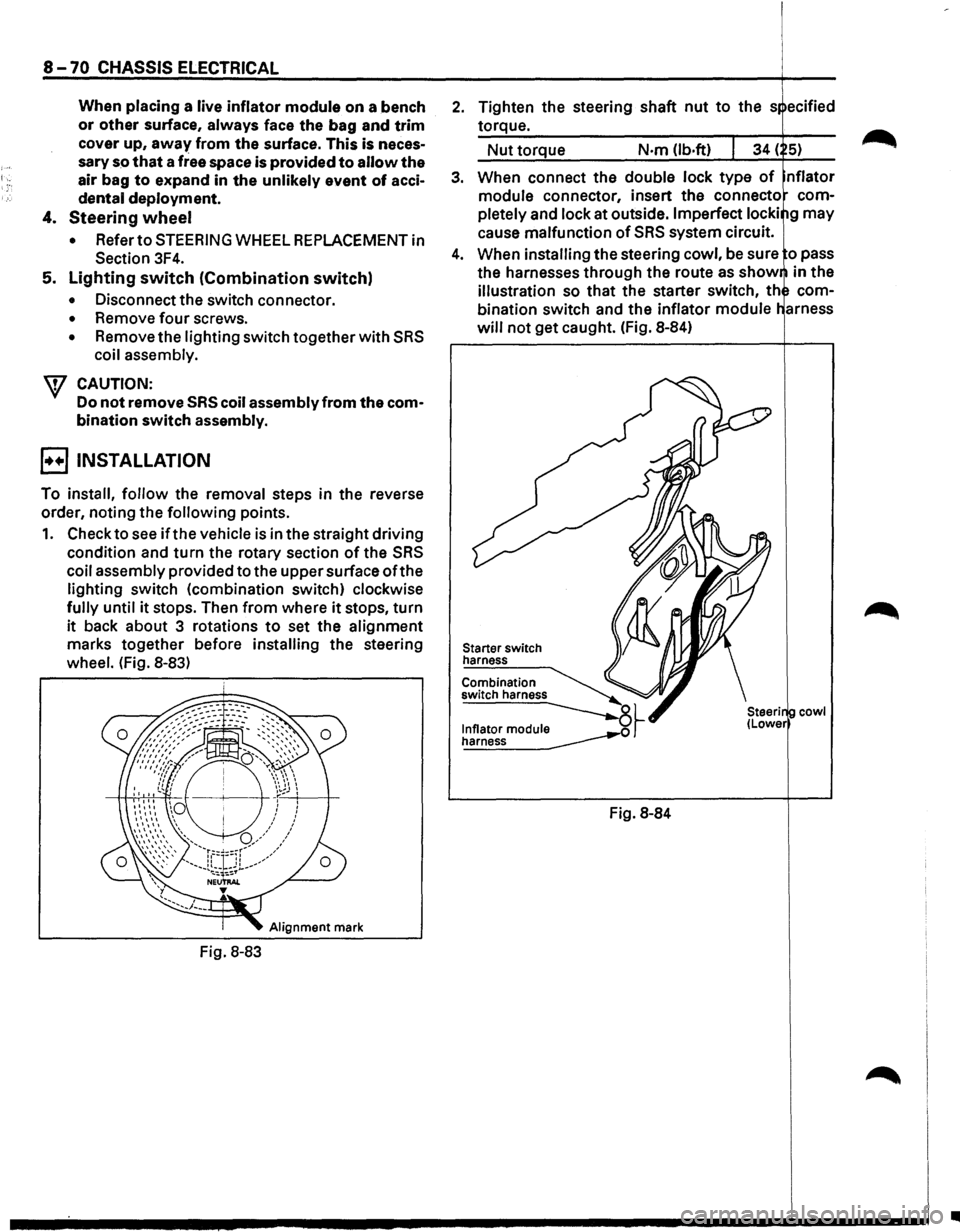
1. Check to see if the vehicle is in the straight driving
condition and turn the rotary section of the SRS
coil assembly provided to the upper surface ofthe
lighting switch (combination switch) clockwise
fully until it stops. Then from where it stops, turn
it back about 3 rotations to set the alignment
marks together before installing the steering
wheel. (Fig. 8-83)
Alignment mark
Fig. 8-83
2. Tighten the steering shaft nut to the s ecified
torque.
Nut torque N·m (lb.ft)
3. When connect the double lock type of nflator
module connector, insert the connecto com
pletely
and lock at outside. Imperfect locki g may
cause malfunction of SRS system circuit.
4. When installing the steering cowl, be sure o pass
the harnesses
through the route as show in the
illustration so that the starter switch, th com
bination switch and the inflator module
will not get caught. (Fig. 8-84)
Starter switch
harness
Combination
switch harness
~~ ~
Fig. 8-84
cowl
•
Page 1261 of 1928
DIMMER·PASSING SWITCH (COMBI
NATION SWITCH)
The headlight beams can be turned to high and low
alternately by pulling the switch lever up to the limit.
Also, the passing light can be flashed by operating the
switch lever within the range before the dimmer
switch has been changed over. The switch lever
returns automatically to its original position.
CHASSIS ELECTRICAL 8 -71
~ INSPECTION
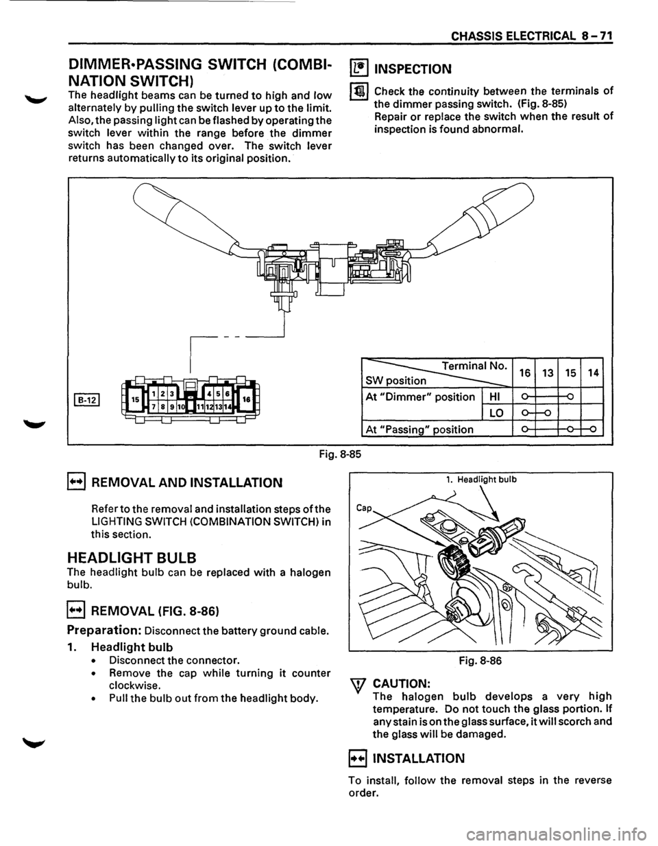
lt!l Check the continuity between the terminals of
the dimmer passing switch. (Fig. 8-85)
Repair
or replace the switch when the result of
inspection is found abnormal.
~· s 16 13 15 14
At "Dimmer" position HI ~ ~ -
LO o-f-o
At "Passing" position ~ ~ ~
Fig.
8-85
E] REMOVAL AND INSTALLATION
Refer to the removal and installation steps oft he
LIGHTING SWITCH (COMBINATION SWITCH) in
this section.
HEADLIGHT BULB
The headlight bulb can be replaced with a halogen
bulb.
E] REMOVAL (FIG. 8-86)
Preparation: Disconnect the battery ground cable.
1. Headlight bulb
• Disconnect the connector.
• Remove the cap while turning it counter
clockwise.
• Pull the bulb out from the headlight body.
1. Headlight bulb
Fig. 8-86
W CAUTION:
The halogen bulb develops a very high
temperature. Do not touch the glass portion. If
any stain is on the glass surface, it will scorch and
the glass will be damaged.
B INSTALLATION
To install, follow the removal steps in the reverse
order.
Page 1278 of 1928
8 -88 CHASSIS ELECTRICAL
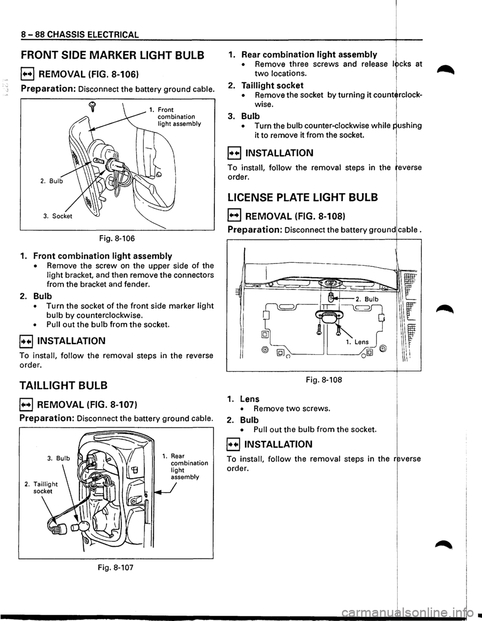
FRONT SIDE MARKER LIGHT BULB
E) REMOVAL (FIG. 8-106)
Preparation: Disconnect the battery ground cable.
Fig. 8-106
1. Front
combination
light assembly
1. Front combination light assembly
• Remove the screw on the upper side of the
light bracket, and then remove the connectors
from the bracket and fender.
2. Bulb
• Turn the socket of the front side marker light
bulb by counterclockwise.
• Pull out the bulb from the socket.
8 INSTALLATION
To install, follow the removal steps in the reverse
order.
TAILLIGHT BULB
EJ REMOVAL (FIG. 8-107)
Preparation: Disconnect the battery ground cable.
Fig. 8-107
1. Rear combination light
assembly
1. Rear combination light assembly
• Remove three screws and release I cks at
two locations.
2. Taillight socket
• Remove the socket by turning it count rclock
wise.
3. Bulb
• Turn the bulb counter-clockwise while
it to remove it from the socket.
8 INSTALLATION i
To install, follow the removal steps in the everse
order.
LICENSE PLATE LIGHT BULB 1.
E) REMOVAL (FIG. 8-108)
Preparation: Disconnect the battery ground cable.
Fig. 8-108
1. Lens
• Remove two screws.
2.
Bulb
• Pull out the bulb from the socket.
8 INSTALLATION
To install, follow the removal steps in the r verse
order.
..
Page 1279 of 1928
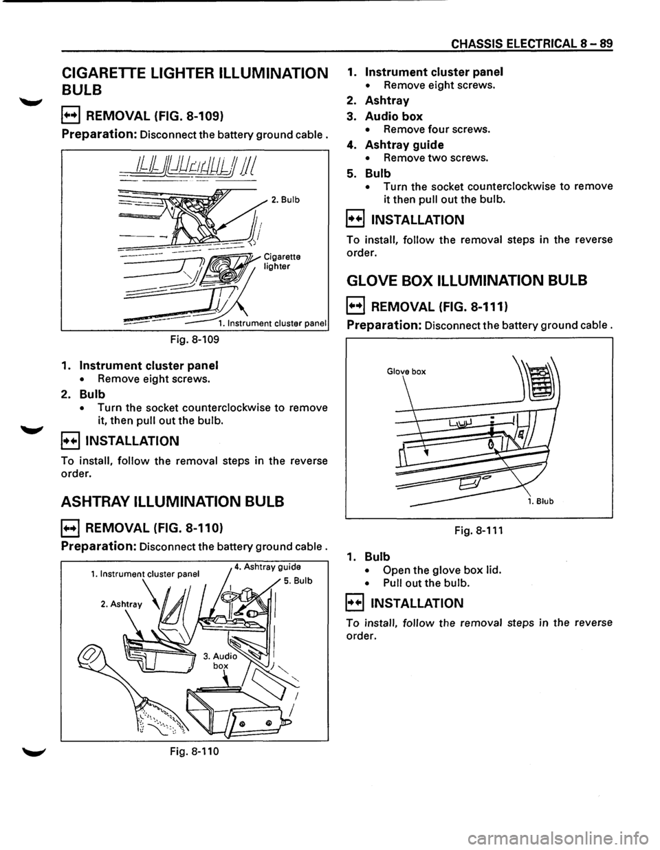
CIGARETTE LIGHTER ILLUMINATION
BULB
E) REMOVAL (FIG. 8-109)
Preparation: Disconnect the battery ground cable.
__ 1JJjj})dr:-~tJUJJJ 11 I
Fig. 8-109
1. Instrument cluster panel
• Remove eight screws.
2. Bulb
2. Bulb
• Turn the socket counterclockwise to remove
it, then
pull out the bulb.
B INSTALLATION
To install, follow the removal steps in the reverse
order.
ASHTRAY ILLUMINATION BULB
E) REMOVAL (FIG. 8-110)
Preparation: Disconnect the battery ground cable.
Fig. 8-110
CHASSIS ELECTRICAL 8-89
1. Instrument cluster panel
• Remove eight screws.
2. Ashtray
3. Audio box
• Remove four screws.
4. Ashtray guide
• Remove two screws.
5. Bulb
• Turn the socket counterclockwise to remove
it then pull out the bulb.
B INSTALLATION
To install, follow the removal steps in the reverse
order.
GLOVE BOX ILLUMINATION BULB
E) REMOVAL (FIG. 8-111)
Preparation: Disconnect the battery ground cable.
Fig.8-111
1. Bulb
• Open the glove box lid.
• Pull
out the bulb.
B INSTALLATION
To install, follow the removal steps in the reverse
order.
Page 1291 of 1928
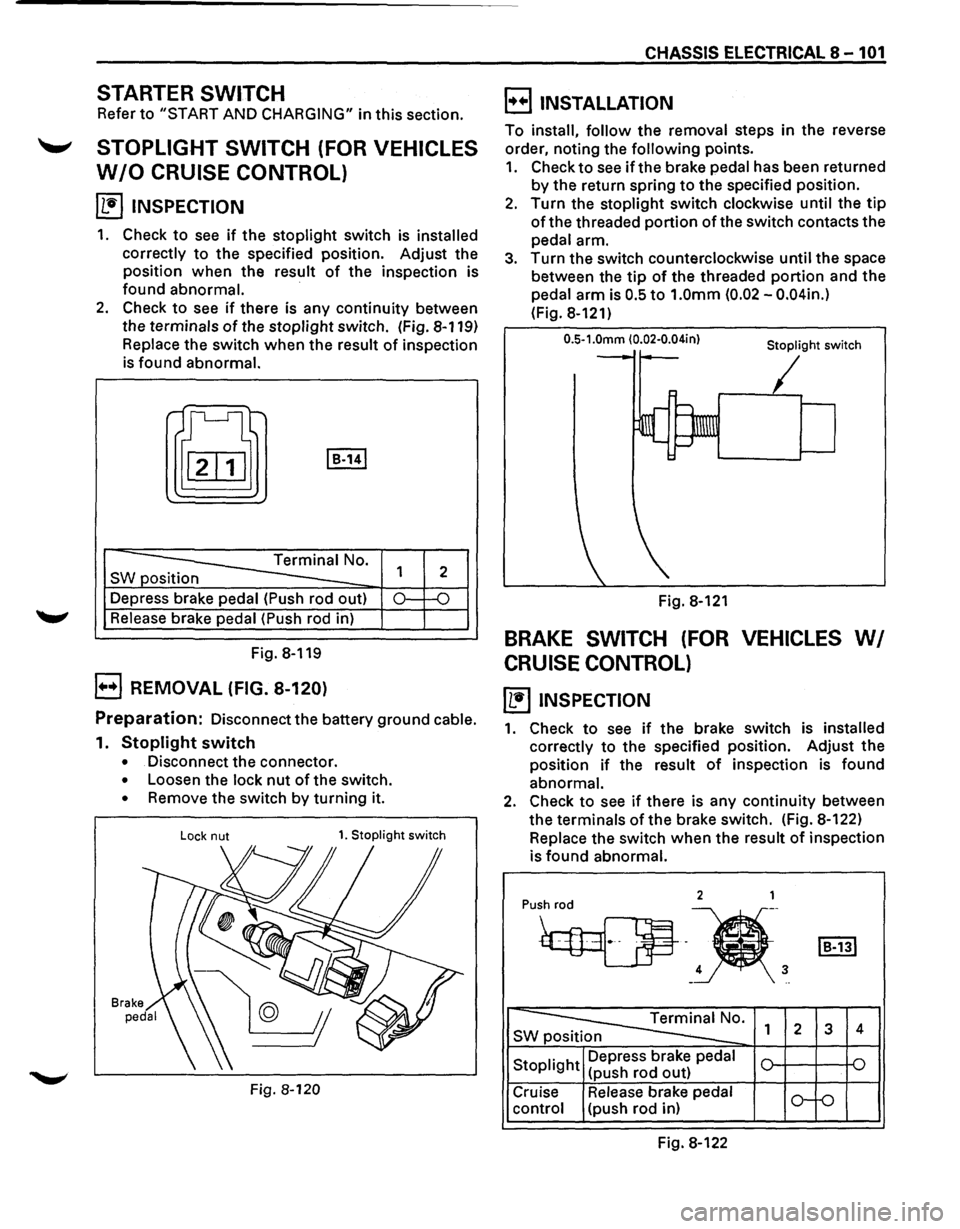
STARTER SWITCH
Refer to "START AND CHARGING" in this section.
'-' STOPLIGHT SWITCH (FOR VEHICLES
W/0 CRUISE CONTROL)
~ INSPECTION
1. Check to see if the stoplight switch is installed
correctly
to the specified position. Adjust the
position when the result
of the inspection is
found abnormal.
·
2. Check to see if there is any continuity between
the terminals
of the stoplight switch. (Fig. 8-119)
Replace the switch when the result of inspection
is found abnormal.
t[J I B-141
-----==== Terminal No.
SW position
--Depress brake pedal (Push rod out)
Release brake pedal (Push rod in)
Fig. 8-119
B REMOVAL (FIG. 8-120)
1
2
0.: -o
Preparation: Disconnect the battery ground cable.
1. Stoplight switch
• Disconnect the connector.
• Loosen the lock nut of the switch.
• Remove the switch by turning it.
Lock nut 1. Stoplight switch
Fig. 8-120
CHASSIS ELECTRICAL 8-101
B INSTALLATION
To install, follow the removal steps in the reverse
order, noting the
following points.
1. Check to see if the brake pedal has been returned
by the return spring to the specified position.
2. Turn the stoplight switch clockwise until the tip
of the threaded portion of the switch contacts the
pedal arm.
3. Turn the switch counterclockwise until the space
between the
tip of the threaded portion and the
pedal arm is
0.5 to 1.0mm (0.02 -0.04in.)
(Fig. 8-121)
0.5-1.0mm (0.02·0.04in} Stoplight switch
Fig. 8-121
BRAKE SWITCH (FOR VEHICLES WI
CRUISE CONTROL)
~ INSPECTION
1. Check to see if the brake switch is installed
correctly
to the specified position. Adjust the
position
if the result of inspection is found
abnormal.
2. Check to see if there is any continuity between
the terminals
of the brake switch. (Fig. 8-122)
Replace the switch
when the result of inspection
is
found abnormal.
2 1
Pu•h
4 3 -..
~0. SWp 1 2 3 4
Stoplight Depress
brake pedal
(push rod out)
Cruise Release brake pedal
o-f-o control (push rod in)
Fig. 8-122
Page 1292 of 1928
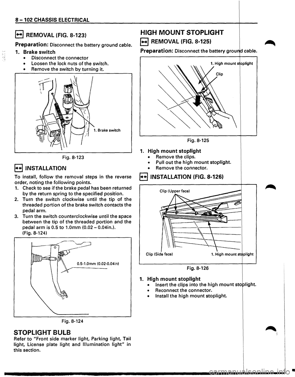
8-102 CHASSIS ELECTRICAL
B REMOVAL (FIG. 8-123)
Preparation: Disconnect the battery ground cable.
1. Brake switch
• Disconnect the connector
• Loosen the lock nuts of the switch.
• Remove the switch by turning it.
Fig. 8-123
B INSTALLATION
1. Brake switch
To install, follow the removal steps in the reverse
order, noting the
following points.
1. Check to see if the brake pedal has been returned
by the return spring to the specified position.
2. Turn the switch clockwise until the tip of the
threaded
portion ofthe brake switch contacts the
pedal arm.
3. Turn the switch counterclockwise until the space
between the
tip of the threaded portion and the
pedal
arm is 0.5 to 1.0mm (0.02-0.04in.).
(Fig. 8-124)
0.5-1.0mm (0.02-0.04in)
Fig. 8-124
STOPLIGHT BULB
Refer to "Front side marker light, Parking light, Tail
light, License plate
light and Illumination light" in
this section.
HIGH MOUNT STOPLIGHT
EJ REMOVAL (FIG. 8-125) ~
Preparation: Disconnect the battery grou d cable.
1. High mounts oplight
Fig. 8-125
1. High mount stoplight
• Remove the clips.
• Pull out the high mount stoplight.
• Remove the connector.
B INSTALLATION (FIG. 8-126)
Clip !Side face) 1. High mount st plight
Fig. 8-126
1. High mount stoplight
• Insert the clips into the high mount sto light.
• Reconnect the connector.
• Install the high mount stoplight.
•
Page 1311 of 1928
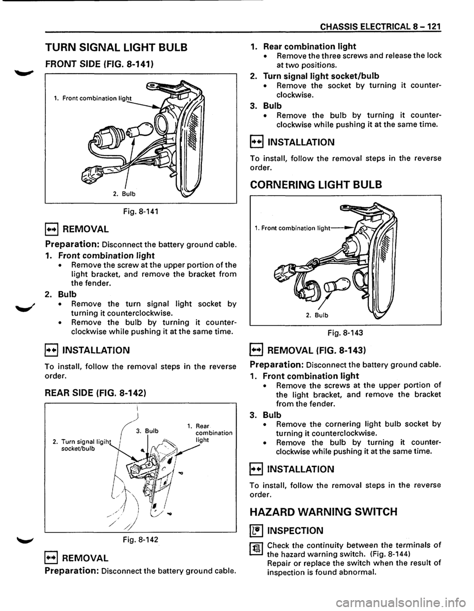
TURN SIGNAL LIGHT BULB
FRONT SIDE (FIG. 8-141)
Fig. 8-141
B REMOVAL
Preparation: Disconnect the battery ground cable.
1. Front combination light
• Remove the screw at the upper portion of the
light bracket, and remove the bracket from
the fender.
2. Bulb
• Remove the turn signal light socket by
turning it counterclockwise.
• Remove the bulb by turning it counter
clockwise
while pushing it at the same time.
B INSTALLATION
To install, follow the removal steps in the reverse
order.
REAR SIDE (FIG. 8-142)
~ Fig. 8-142
B REMOVAL
Preparation: Disconnect the battery ground cable.
CHASSIS ELECTRICAL 8-121
1. Rear combination light
• Remove the three screws and release the lock
at
two positions.
2. Turn signal light socket/bulb
• Remove the socket by turning it counter
clockwise.
3. Bulb
• Remove the bulb by turning it counter
clockwise
while pushing it at the same time.
B INSTALLATION
To install, follow the removal steps in the reverse
order.
CORNERING LIGHT BULB
Fig. 8-143
EJ REMOVAL (FIG. 8-143)
Preparation: Disconnect the battery ground cable.
1. Front combination light
• Remove the screws at the upper portion of
the light bracket, and remove the bracket
from the fender.
3. Bulb
• Remove the cornering light bulb socket by
turning it counterclockwise.
• Remove the bulb by turning it counter
clockwise while pushing it at the same time.
E) INSTALLATION
To install, follow the removal steps in the reverse
order.
HAZARD WARNING SWITCH
~ INSPECTION
rfll Check the continuity between the terminals of
~ the hazard warning switch. (Fig. 8-144)
Repair
or replace the switch when the result of
inspection is found abnormal.
Page 1314 of 1928
8-124 CHASSIS ELECTRICAL
1. Backup light switch For low note (Fig.S-151)
• Remove the connectors.
• Remove the switch by turning it counter
clockwise.
B INSTALLATION
To install, follow the removal steps in the reverse
order,
noting the following point.
1.
Backup light switch
li:i1 • Apply liquid gasket to the screw portion of
~ the switch to prevent oil leak.
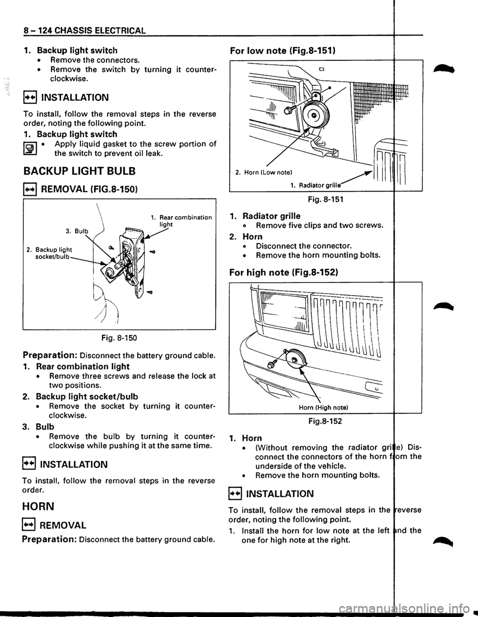
BACKUP LIGHT BULB
B REMOVAL (FIG.S-150)
2. Backup light
socket/bulb
i ''V
f
~h /) i/
Fig. 8-150
Preparation: Disconnect the battery ground cable.
1. Rear combination light
• Remove three screws and release the lock at
two positions.
2.
Backup light socket/bulb
• Remove the socket by turning it counter
clockwise.
3. Bulb
• Remove the bulb by turning it counter
clockwise
while pushing it at the same time.
B INSTALLATION
To install, follow the removal steps in the reverse
order.
HORN
B REMOVAL
Preparation: Disconnect the battery ground cable.
Fig. 8-151
1.
Radiator grille
o Remove five clips and two screws.
2. Horn
o Disconnect the connector.
• Remove the horn mounting bolts.
For high note (Fig.S-152)
Horn (High note)
Fig.8-152
1. Horn
• {Without removing the radiator gri e) Dis
connect the connectors of the horn f om the
underside
of the vehicle.
•
Remove the horn mounting bolts.
8 INSTALLATION
To install, follow the removal steps in the everse
order, noting the
following point.
1. Install the horn for low note at the left nd the
one
for high note at the right. ~