clock ISUZU TROOPER 1995 Repair Manual
[x] Cancel search | Manufacturer: ISUZU, Model Year: 1995, Model line: TROOPER, Model: ISUZU TROOPER 1995Pages: 1928
Page 1808 of 1928
10-50 BODY
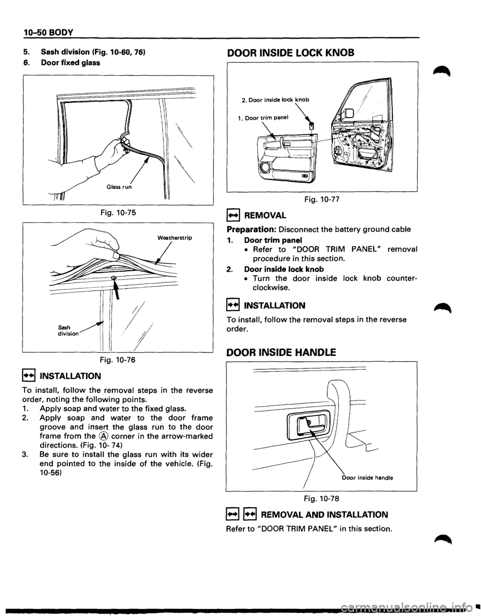
5. Sash division (Fig. 10-60, 76)
6. Door fixed glass
Sash division
Fig. 10-75
I
.···;
Fig. 10-76
I••IINSTALLATION
Weatherstrip
To install, follow the removal steps in the reverse
order,
noting the following points.
1. Apply soap and water to the fixed glass.
2. Apply soap and water to the door frame
groove and insert the glass run to the door
frame from the @ corner in the arrow-marked
directions. (Fig.
10-74)
3. Be sure to install the glass run with its wider
end pointed to the inside of the vehicle. (Fig.
10-56)
DOOR INSIDE LOCK KNOB
2. Door inside lock knob
1. Door trim panel
Fig. 10-77
1++1 REMOVAL
Preparation: Disconnect the battery ground cable
1. Door trim panel
•
Refer to "DOOR TRIM PANEL" removal
procedure in
this section.
2. Door inside lock knob
• Turn the door inside lock knob counter
clockwise.
!••I INSTALLATION
To install, follow the removal steps in the reverse
order.
DOOR INSIDE HANDLE
Door inside handle
Fig. 10-78
1++11++1 REMOVAL AND INSTALLATION
Refer to "DOOR TRIM PANEL" in this section.
II
Page 1837 of 1928
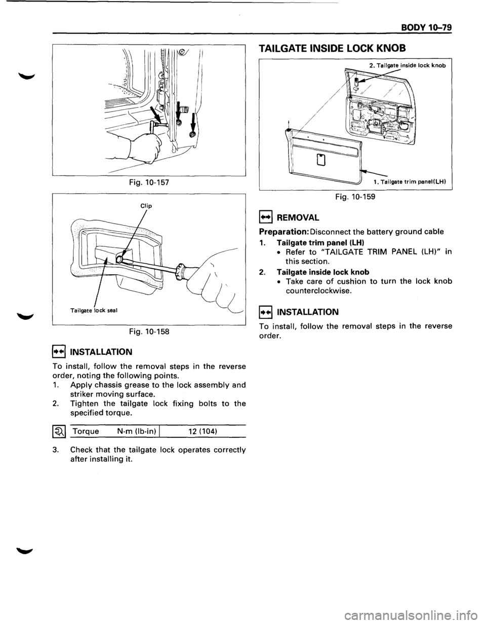
Fig. 10-157
Clip
Tailgate lock seal
Fig. 10-158
I••! INSTALLATION
')
To install, follow the removal steps in the reverse
order,
noting the following points.
1. Apply chassis grease to the lock assembly and
striker
moving surface.
2. Tighten the tailgate lock fixing bolts to the
specified torque.
~~~ Torque N·m (lb·in) I 12 (104)
3. Check that the tailgate lock operates correctly
after installing it.
BODY 10-79
TAILGATE INSIDE LOCK KNOB
2. Tailgate inside lock knob
Fig. 10-159
1•+1 REMOVAL
Preparation: Disconnect the battery ground cable
1. Tailgate trim panel (LH)
• Refer to "TAIL GATE TRIM PANEL (LH)" in
this section.
2. Tailgate inside lock knob
• Take care of cushion to turn the lock knob
counterclockwise.
I••IINSTALLATION
To install, follow the removal steps in the reverse
order.
Page 1855 of 1928
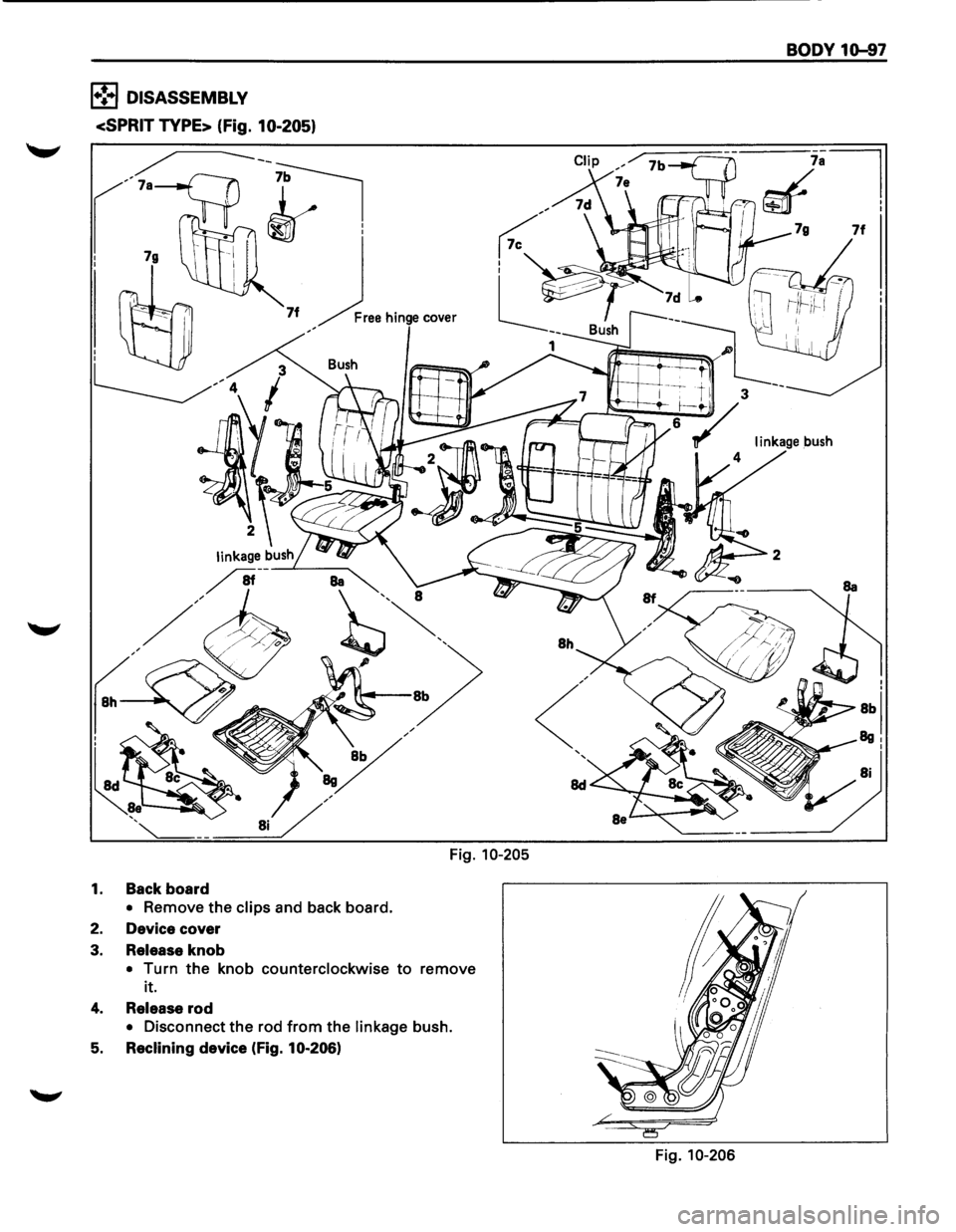
1•!3 DISASSEMBLY
1.
2.
3.
4.
5.
Back board
• Remove the clips and back board.
Device cover
Release knob
Fig. 10-205
•
!urn the knob counterclockwise to remove
lt.
Release rod
• Disconnect the rod from the linkage bush.
Reclining device (Fig. 10-206)
BODY 1G-97
Fig. 10-206
Page 1857 of 1928
,__,.
3
1
Linkage bush
7d
--L·W·B I
Linkage bush
7c
BODY 1D-99
S·W·B
==c=
6g
L ___ _
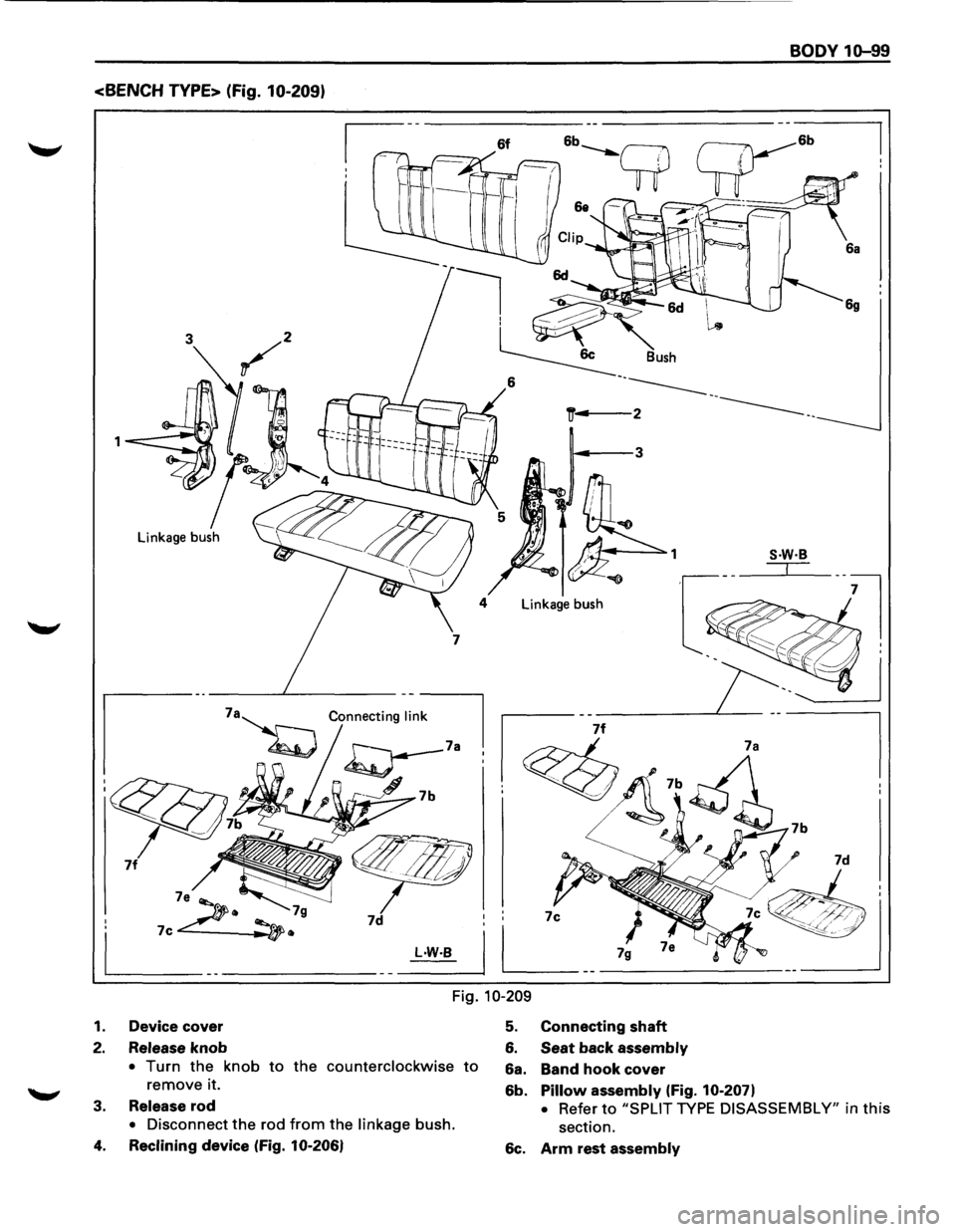
Fig. 10-209
1. Device cover 5. Connecting shaft
2. Release knob 6. Seat back assembly
• Turn the knob to the counterclockwise to 6a. Band hook cover remove it.
6b. Pillow assembly (Fig. 10-207)
3. Release rod • Refer to "SPLIT TYPE DISASSEMBLY" in this
• Disconnect the rod from the linkage bush. section .
4. Reclining device (Fig. 10-2061 6c. Arm rest assembly
Page 1869 of 1928
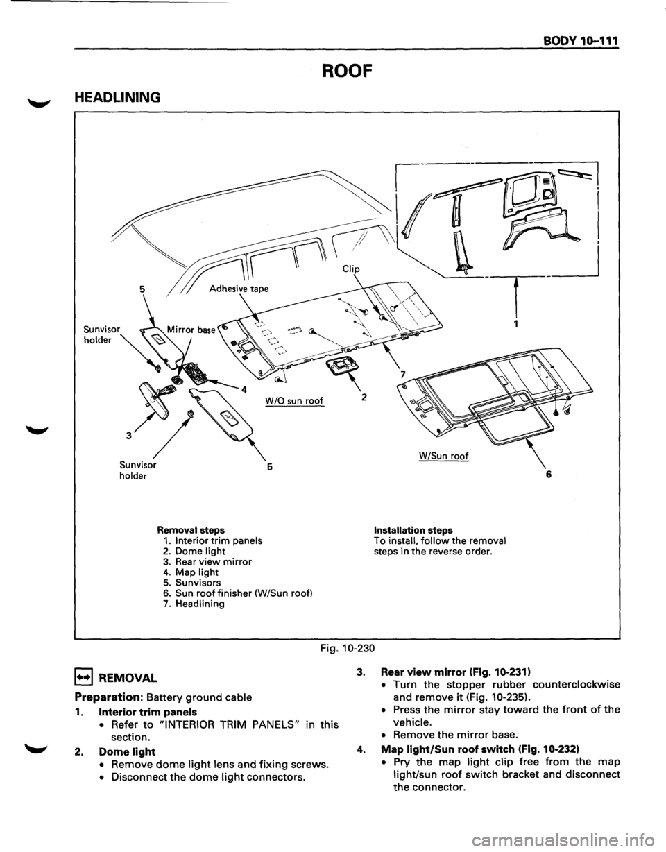
BODY 10-111
ROOF
HEADLINING
~---~~I
~r CUp ''-. _ __j
5 1 Adh.,;,;, tap• . T
1
W /0 sun roof 2
Sunvisor
holder 5
Removal steps 1. Interior trim panels 2. Dome light 3. Rear view mirror 4. Map light 5. Sunvisors 6. Sun roof finisher (W/Sun roof) 7. Headlining W/Sun
roof
Installation steps To install, follow the removal steps
in the reverse order. 6
Fig. 10-230
1••1 REMOVAL
Preparation: Battery ground cable
1. Interior trim panels
•
Refer to "INTERIOR TRIM PANELS" in this
section.
2. Dome light
• Remove dome light lens and fixing screws.
• Disconnect the dome light connectors.
3. Rear view mirror (Fig. 10-231)
• Turn the stopper rubber counterclockwise
and remove
it (Fig. 10-235).
• Press the mirror stay toward the front of the
vehicle.
•
Remove the mirror base.
4. Map light/Sun roof switch (Fig. 10-232)
• Pry the map light clip free from the map
light/sun roof switch bracket and disconnect
the connector.
Page 1892 of 1928
10-134 BODY
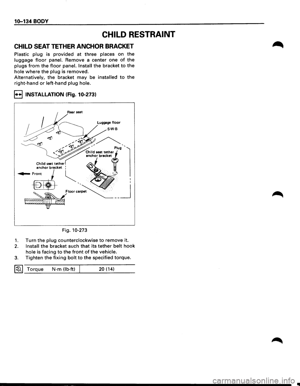
CHILD RESTRAINT
CHILD SEAT TETHER ANCHOR BRACKET
Plastic plug is provided at three places on the
luggage floor panel. Remove a center one of the
plugs from the floor panel. Install the bracket to the
hole where the plug is removed.
Alternatively, the bracket may be installed to the
right-hand
or left-hand plug hole.
I••IINSTALLATION (Fig. 10-273)
,/<(!.., )~ ~ .., "' ' "'"' '''-'"-"' ' Plug '
'-."" anchor bracket r ... --
~Front ~ ~ ,.
-®liJ ', • :
~loom~ __ j
F?»
Fig. 10-273
1. Turn the plug counterclockwise to remove it.
2. Install the bracket such that its tether belt hook
hole is facing to the front of the vehicle.
3. Tighten the fixing bolt to the specified torque.
~~~ Torque N-m (lb·ft) 20 (14)