clock ISUZU TROOPER 1995 Owner's Manual
[x] Cancel search | Manufacturer: ISUZU, Model Year: 1995, Model line: TROOPER, Model: ISUZU TROOPER 1995Pages: 1928
Page 1070 of 1928
7A-198 AUTOMATIC TRANSMISSION (4L30-E)
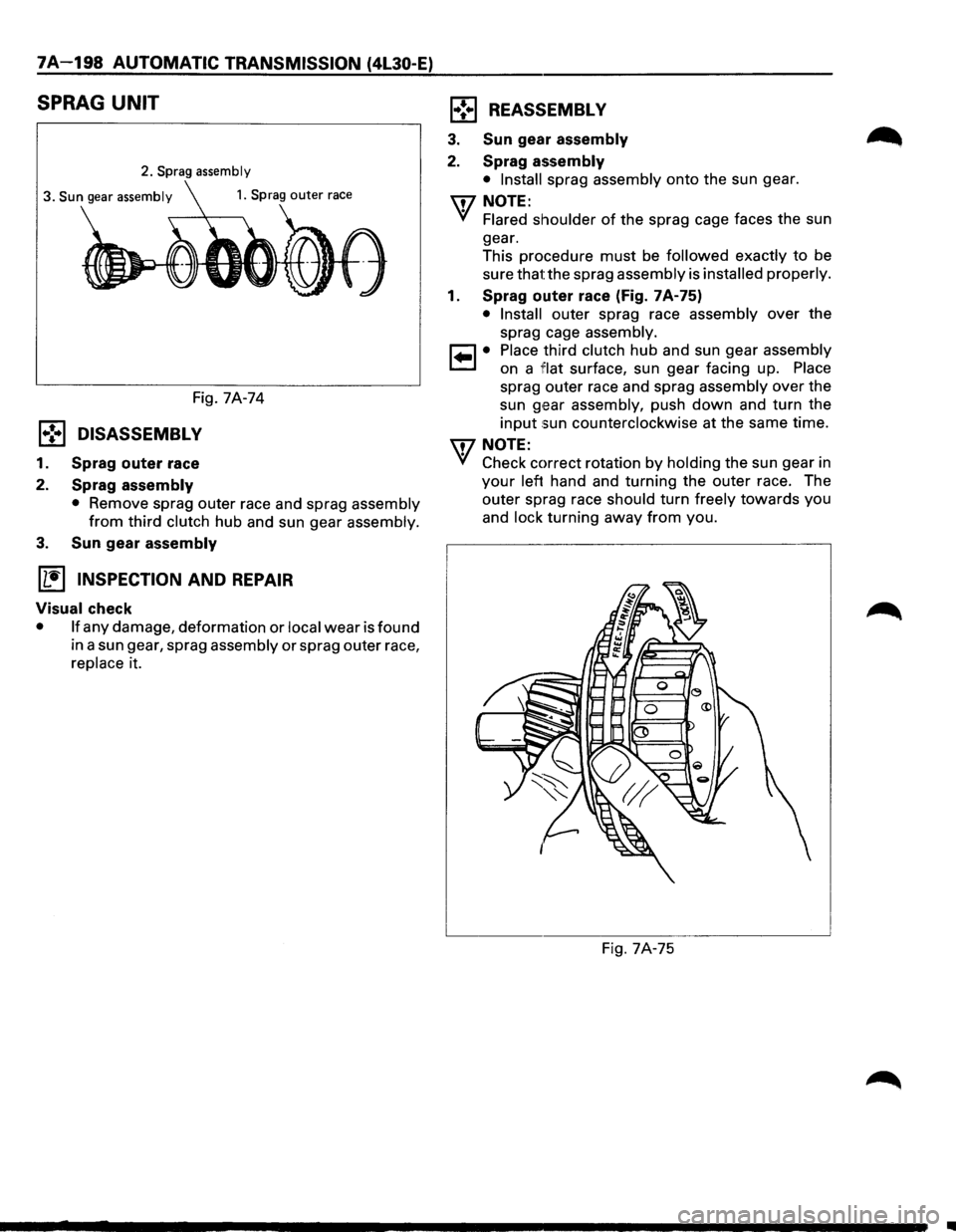
SPRAG UNIT
2. Sprag assembly
3. Sun gear assembly
Fig. 7A-74
1.,!•1 DISASSEMBLY
1. Sprag outer race
2.
Sprag assembly
• Remove sprag outer race and sprag assembly
from third clutch hub and sun gear assembly.
3. Sun gear assembly
(1!] INSPECTION AND REPAIR
Visual check
• If any damage, deformation or local wear is found
in a sun gear, sprag assembly or sprag outer race,
replace it.
1•! .. 1 REASSEMBLY
3. Sun gear assembly
2. Sprag assembly
• Install sprag assembly onto the sun gear.
\fl NOTE:
VI Flared shoulder of the sprag cage faces the sun
gear.
This procedure
must be followed exactly to be
sure that the sprag assembly is
installed properly.
1. Sprag outer race (Fig. 7A-75)
• Install outer sprag race assembly over the
sprag cage assembly.
1•1• Place third clutch hub and sun gear assembly
on a
1Fiat surface, sun gear facing up. Place
sprag outer race and sprag assembly over the
sun
g,ear assembly, push down and turn the
input sun counterclockwise at the same time.
\fl NOTE:
VI Check correct rotation by holding the sun gear in
your left hand and turning the outer race. The
outer sprag race should turn freely
towards you
and
lock turning away from you.
Fig. 7A-75
•
Page 1078 of 1928
7A-206 AUTOMATIC TRANSMISSION (4L30-E)
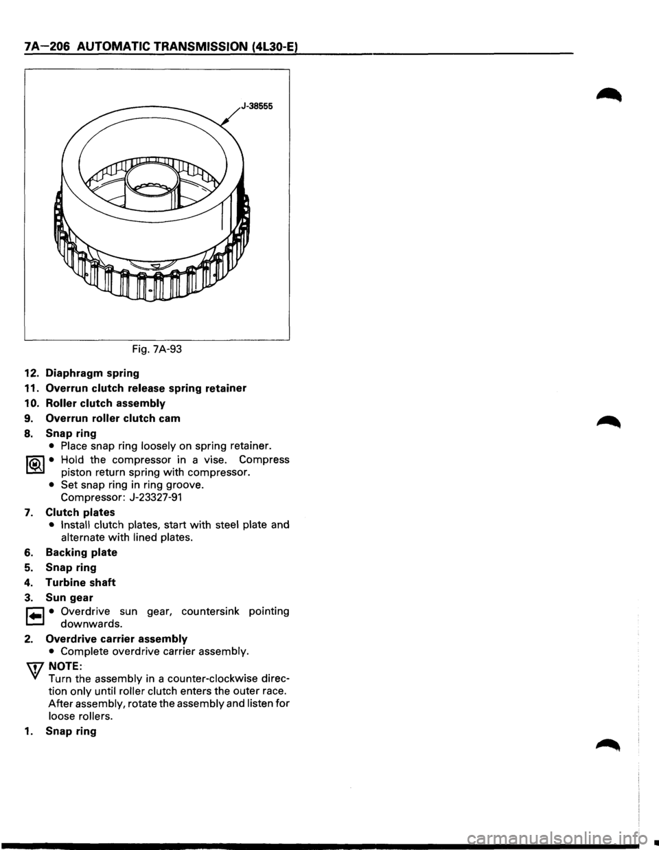
Fig. 7A-93
12. Diaphragm spring
11. Overrun clutch release spring retainer
1 0. Roller clutch assembly
9. Overrun roller clutch cam
8. Snap ring
• Place snap ring loosely on spring retainer.
I®J • Hold the compressor in a vise. Compress
piston return spring
with compressor.
• Set snap ring in ring groove.
Compressor: J-23327-91
7. Clutch plates
• Install clutch plates, start with steel plate and
alternate with lined plates.
6. Backing plate
5. Snap ring
4. Turbine shaft
3. Sun gear
r=l • Overdrive sun gear, countersink pointing
t=.l downwards.
2. Overdrive carrier assembly
• Complete overdrive carrier assembly.
\i7 NOTE:
VI Turn the assembly in a counter-clockwise direc
tion
only until roller clutch enters the outer race.
After assembly, rotate the assembly and listen for
loose rollers.
1. Snap ring
•
Page 1104 of 1928
78-14 MANUAL TRANSMISSION
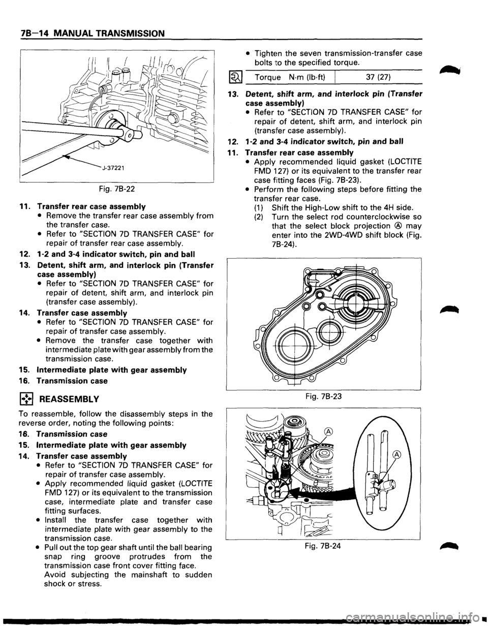
Fig. 78-22
11. Transfer rear case assembly
• Remove the transfer rear case assembly from
the transfer case.
• Refer to "SECTION 7D TRANSFER CASE" for
repair
of transfer rear case assembly.
12. 1-2 and 3-4 indicator switch, pin and ball
13. Detent, shift arm, and interlock pin (Transfer
case
assembly)
• Refer to "SECTION 7D TRANSFER CASE" for
repair of detent, shift arm, and interlock pin
(transfer case assembly).
14. Transfer case assembly
• Refer to "SECTION 7D TRANSFER CASE" for
repair
of transfer case assembly.
• Remove the transfer case together with
intermediate plate with gear assembly from the
transmission case.
15. Intermediate plate with gear assembly
16. Transmission case
l•!•l REASSEMBLY
To reassemble, follow the disassembly steps in the
reverse order, noting the following points:
16. Transmission case
15.
Intermediate plate with gear assembly
14. Transfer case assembly
• Refer to "SECTION 7D TRANSFER CASE" for
repair
of transfer case assembly.
• Apply recommended liquid gasket (LOCTITE
FMD 127) or its equivalent to the transmission
case, intermediate plate and transfer case
fitting surfaces.
• Install the transfer case together with
intermediate plate with gear assembly to the
transmission case.
• Pull out the top gear shaft until the ball bearing
snap ring groove protrudes
from the
transmission case
front cover fitting face.
Avoid subjecting the mainshaft
to sudden
shock
or stress.
• Tightem the seven transmission-transfer case
bolts
ito the specified torque.
I~I __ T_o_rq~u __ e __ N_·_m_(~lb_·f~t)~ ______ 3_7_(2_7~) ____ _
13. Detent, shift arm, and interlock pin (Transfer
case
assembly)
• Refer to "SECTION 7D TRANSFER CASE" for
repair of detent, shift arm, and interlock pin
(transfer case assembly).
12. 1-2 and 3-4 indicator switch, pin and ball
11. Transfe1· rear case assembly
• Apply recommended liquid gasket (LOCTITE
FMD 127) or its equivalent to the transfer rear
case fitting faces (Fig. 78-23).
• Perform the following steps before fitting the
transf13r rear case.
(1) Shift the High-Low shift to the 4H side.
(2) Turn the select rod counterclockwise so
that the select block projection ® may
enter into the 2WD-4WD shift block (Fig.
78-24).
Fig. 78-23
Fig. 78-24
•
Page 1143 of 1928
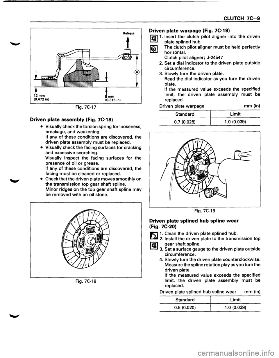
Fig. 7C-17
mm (0.315 in)
Driven plate assembly (Fig. 7C-18)
Release
t
• Visually check the torsion spring for looseness,
breakage, and weakening.
If any of these conditions are discovered, the
driven
plate assembly must be replaced.
• Visually check the facing surfaces for cracking
and excessive scorching.
Visually inspect the facing surfaces for the
presence
of oil or grease.
If any of these conditions are discovered, the
facing
must be cleaned or replaced.
• Check that the driven plate moves smoothly on
the transmission
top gear shaft spline.
Minor ridges on the top gear shaft spline may
be removed
with an oil stone.
Fig. 7C-18
CLUTCH 7C-9
Driven plate warpage (Fig. 7C-19)
l'fil1. Insert the clutch pilot aligner into the driven
1.!!!1 plate splined hub.
li5\l The clutch pilot aligner must be held perfectly
I.::2Y horizontal.
Clutch pilot
aligner; J-24547
2. Set a dial indicator to the driven plate outside
circumference.
3. Slowly turn the driven plate.
Read the dial indicator as you turn the driven
plate.
If
the measured value exceeds the specified
limit, the driven plate assembly must be
replaced.
Driven
plate warpage mm (in)
Standard Limit
0.7 (0.028) 1.0
(0.039)
Fig. 7C-19
Driven plate splined hub spline wear
(Fig.
7C-20)
E1 1. Clean the driven plate splined hub.
l...al 2. Install the driven plate to the transmission top
ffi1 gear shaft spline.
1.!!1 3. Set a surface gauge to the driven plate outside
circumference.
4. Slowly turn the driven plate counterclockwise.
Measure the
spline rotation play as you turn the
driven
plate.
If
the measured value exceeds the specified
limit, the driven plate assembly must be
replaced.
Driven
plate splined hub spline wear mm (in)
Standard Limit
0.5 (0.020) 1.0 (0.039)
Page 1167 of 1928
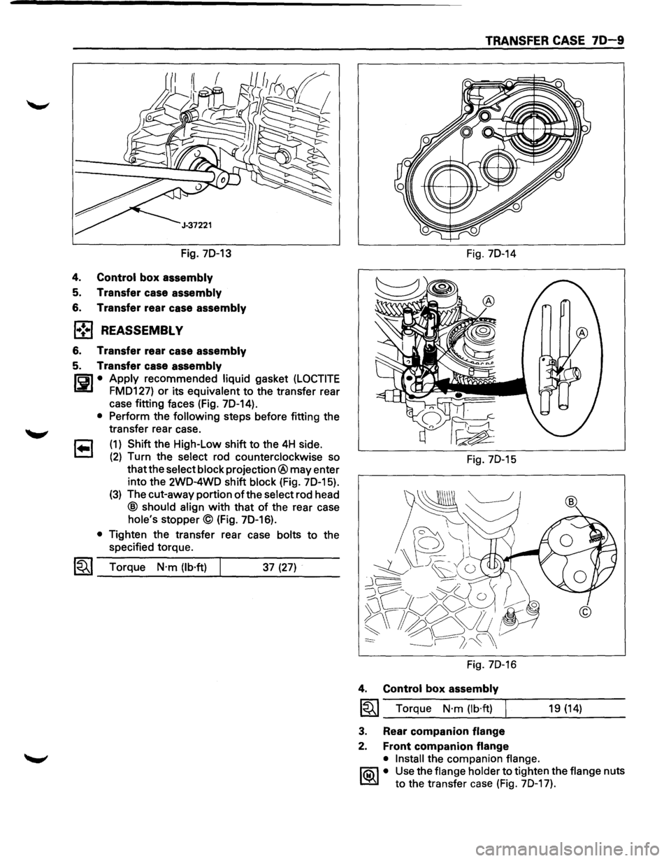
Fig. 70-13
4.
Control box assembly
5. Transfer case assembly
6. Transfer rear case assembly
l•!•l REASSEMBLY
6. Transfer rear case assembly
5. Transfer case assembly
1'61 • Apply recommended liquid gasket (LOCTITE
Li!:l FM0127) or its equivalent to the transfer rear
case fitting faces (Fig. 70-14).
• Perform the following steps before fitting the
transfer rear case.
1 .. 1 (1) Shift the High-Low shift to the 4H side.
(2) Turn the select rod counterclockwise so
that the select block projection® may enter
into the 2W0-4WO shift
block (Fig. 70-15).
(3) The cut-away portion of the select rod head
@ should align with that of the rear case
hole's stopper© (Fig. 70-16).
• Tighten the transfer rear case bolts to the
specified torque.
1~1 Torque N·m (lb·ft) 37 (27)
TRANSFER CASE 70-9
Fig. 70-14
Fig. 70-15
Fig. 70-16
4. Control box assembly
~~~ Torque N·m (lb·ft) 19 (14)
3. Rear
companion flange
2. Front companion flange
• Install
the companion flange.
l"iC\l • Use the flange holder to tighten the flange nuts
~ to the transfer case (Fig. 70-17).
Page 1191 of 1928

CHASSIS ELECTRICAL 8-1
·SECTION 8
CHASSIS ELECTRICAL
'\f CAUTION: .
When fasteners are removed, always reinstall them at the same location from which they were removed.
If a fastener needs to be replaced, use the correct part number fastener for that application. If the correct
part number fastener is not
available, a fastener of equal size and strength (or stronger) may be used.
Fasteners that are not reused, and those requiring thread
locking compound, will be called out. The correct
torque
values must be used when installing fasteners that require it. If the above conditions are not
followed, parts or system damage could result.
CONTENTS
General Information .................................... 8-2
Notes for Working on Electrical
Items .................................................... 8-2
Symbols and Abbreviations ................. 8-8
Symbols ............................................ 8-8
Abbreviations ................................... 8-9
Parts for Electrical Circuit ..................... 8-10
Wiring ............................................... 8-10
Fuse .................................................. 8-11
Fusible Link ....................................... 8-12
Circuit Breaker ................................... 8-12
Relay ................................................. 8-12
Relay Specifications and
Configurations ................................ 8-13
Diode ................................................. 8-14
Connector ......................................... 8-15
Reading the Circuit Diagram ................ 8-17
Main Data and Specifications .................... 8-19
Bulb Specifications ................................ 8-19
Fuse,
Fusible Link and
Circuit Breaker Location ..................... 8-21
Fuse
Block Circuit .................................. 8-22
Reference Table of Fuse, Fusible
Link and Circuit Breaker ..................... 8-23
Relay Location ....................................... 8-27
Diode Location .......................................
8-28
Grounding Point .................................... 8-29
Reference Table ................................ 8-29
Location ............................................ 8-31
Cable Harness Routing .......................... 8-34
System Repair .............................................. 8-38
Start and Charging ................................ 8-38
Engine Control Module
(ECM) ................................................... 8-47
Headlight and Fog Light ........................ 8-58
Front Side Marker Light, Parking Light,
Taillight, License Plate Light and
Illumination Light .............................. 8-76
Stoplight and Rear Defogger .............. 8-92
Turn Signal Light, Hazard
Warning
Light, Cornering Light,
Backup
Light and Horn ..................... 8-106
Dome Light, Luggage room Light,
Courtesy Light, Map Light,
Seat Belt Switch and
Warning Buzzer ................................. 8-128
Power Door Lock ................................. 8-142
Power
Window .................................... 8-156
Cruise
Control ...................................... 8-172
Anti-Lock Brake
System (ABS) ........... 8-178
Rear
Wheel Anti-Lock Brake
System (RWAL) ................................. 8-185
Transmission
Control Module
(TCM) ................................................. 8-192
A/T Shift Lock ...................................... 8-200
Windshield
Wiper/Washer and
Rear
Wiper/Washer .......................... 8-205
Headlight wiper /washer ..................... 8-232
Audio, Auto Antenna,
Cigarette
Lighter and digital clock ... 8-246
Power Door Mirror ............................... 8-254
Anti-theft System ................................ 8-270
Meter and Warning/Indicator Light ... 8-288
A/T Shift Indicator ............................... 8-336
Heater and
Air Conditioning ............... 8-340
Sun
Roof ............................................... 8-346
Power Seat ........................................... 8-360
Seat
Heater .......................................... 8-37 4
Supplemental Restraint
System (SRS) -AIR BAG ................... 8-382
Page 1211 of 1928
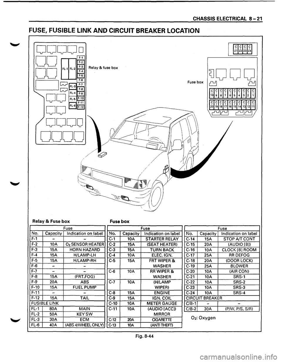
CHASSIS ELECTRICAL 8-21
FUSE, FUSIBLE LINK AND CIRCUIT BREAKER LOCATION
ooooo 112~12~1~1~1
00 E
EEr 00 ~
Relay & fuse box
SJOOO 7-6
I lw ;;::;~ Fuse box ~ ~
1l1~~ ~lff~UIH~Inll
w~ F-a FL-4 ~
00 FL·S~ r---, F-11 'l2~J1~ 1~1&11~11~1,\l~31hl1~1
0
0
FL-6 'F-i2
I' ~
\a~ a~;
0000
0000
I ~
l/
~
j
~/~/ e:;?' v II I / / .I / /
('-/ .
~~
-~-~;,a~ ~~ --.:_
~~~~ -
Relay & Fuse box Fuse box
Fuse
Fuse Fuse
No. Capacity Indication on label No. Capacity Indication on label No. Capacity Indication on label
F-1 --C-1 10A STARTER RELAY
C-14 15A STOP A!f CONT
F-2 10A 02 SENSOR HEATER C-2 15A (SEAT HEATER)
C-15 20A (AUDIO [8))
F-3
15A HORN HAZARD C-3 15A
TURN BACK C-16 10A CLOCK (8] ROOM
F-4
15A H/LAMP-LH C-4 10A ELEC.IGN. C-17 25A RR DEFOG
F-5
15A H/LAMP-RH C-5
15A FRTWIPER & C-18 20A (DOOR LOCK)
F-6 --WASHER C-19
25A BLOWER
F-7
- -C-6 10A RRWIPER & C-20 10A (AIR
CON)
F-8
15A (FRT.FOG) WASHER C-21 10A SRS-1
F-9 20A ABS C-7 10A (H/LAMP C-22 10A SRS-2
F-10
15A FUEL PUMP WIPER) C-23 lOA SRS-3
F-11 -
-C-8 15A ENGINE C-24 10A SRS-4
F-12
15A TAIL C-9 15A IGN. COIL CIRCUIT BREAKER
FUSIBLE
LINK
C-10 10A METER GAUGE
C/8-1 --FL-1 80A MAIN C-11 10A
(AUDIO IACC])
C/8-2 30A (P/W, P/S, S/R)
FL-2 50 A KEYSW MIRROR
FL-3 30A ECM C-12 20A CIGARETTE 02: Oxygen
FL-6 40A (ASS 4/WHEEL ONLY) C-13 10A (ANTI THEFT)
Fig. 8-44
Page 1212 of 1928
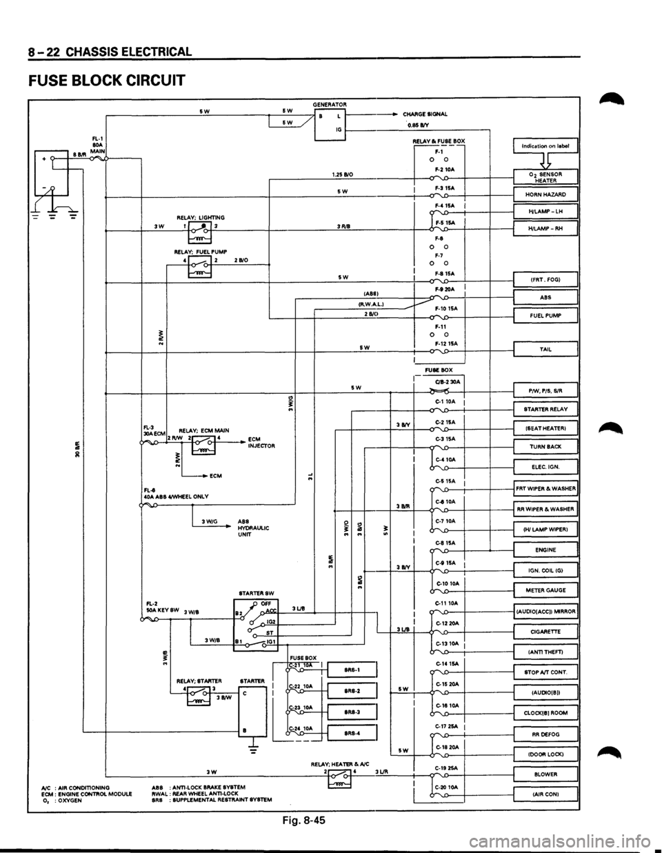
8-22 CHASSIS ELECTRICAL
FUSE BLOCK CIRCUIT
GENERATOR -------------------~s~w~------------~~s~w~--~~~~ r- / B L 1------CHARGE SIGNAL &W _/
FL-1 80A .-----, B 11.'1 MAIN
+ Lt--
l£h
~----/ IG~----------~O~.$~B/V~-----------,
3W REL~HT1NG 1J ---'"~L 3
RELA~PUMP 4 1...---. 12 2 B/0
1.25 B/0
SW
3RJ8
5W
~~~·~ F-1 0 0 F-2 10A
I F-315A
F-8
0 0 F-7 0 0 F-81SA
F-920A
9;nlaool
I
Oz SENSOR HEATER
HORN HAZARD
H/LAMP-LH
H/LAMP-RH
(FRT. FOG)
lABS) -I ABS
I ,--------__:<;;:R·.:.:W.::..Acc·L;;:-1 ____ ----Jv F-10 1SA 2 810
I
~ECM RELAY; ECM MAIN ¢~,...,..J>--+2'-'RIW~_::2~1-o.....-<:>-f-·4.:._ __ _. ~J~CTOR
L...-_.ECM
FL-t 40A ABS 4/WHEEL ONLY
"
.... ...
SW
5W
3 8IY
F-11 0 0 F-1215A
~------' FUSE BOX
CIB-2 30A ~.,.;
C-110A :
C-215A
C-31SA
C-410A
I
J
FUEL PUMP
TAIL
P/W, PIS. SIR
STARTER RELAY
(SEAT HEATER)
TURN BACK
ELEC.IGN.
e-s
15A 1 ""'-.0---t-----+----il FRT WIPER & WASHER
"""' -
I 3W/G
C-810A '---f-+----+.:3.:BIR::::..+---¢""''-£>---i-----f-----jl RR WIPER & WASHER
ABS HYORAULIC UNIT
STARTERSW
FL-2 _JJ OFF
~ ...
..:..AKEYSW 3 W/B ay ' o.N". 3UB
~~--~--~,~------~-0 ~~IG~2Y-----------~ o-: ST 3W/B 81 -.,IG1
FUSE BOX
I
I g1~ 1 J'-:::s:R:s-:1 =I RELAY; STARTER
STARTER I r-
L~---'~-j.t
I I 3UB
sw
C-710A
~';::--~--~-'---~~~HI~LA~M~P~W~IP~E~R~l~~ C-81SA ""'-'>--1---...__---i ENGINE
C-111SA I J~======~l IGN. COIL (G)
C-10 10A
C-1110A
k'-1:>----t----t
~==~I
METER GAUGE
""''-£>---f----------1 (AUDIO[ACC)) MIRROR
C-12 20A
::...1310A I
C-141SA -r"\'-1)----f----t
C-15 20A L,-.
CIGARETTE
(ANTITHEFT)
STOP A/T CONT.
(AUDIO[ B))
C-1810A """"-'-.0---f----------t_j CLOCK[B) ROOM
L---+------------------------iB lt~;_ ~=~~~:~:~::~~~: C-17 2SA I
G1820A
RR DEFOG
= sw (DOOR LOCK) RELAY; HEATER &A/C .:._ __________________ .:.:3~W'-'---------------------~2to~.....-4 3UR C-19 2SA ...... BLOWER
A/C : AIR CONDITIONING ECM : ENGINE CONTIIOL MODULE 0, :OXYGEN ABS
:ANTI-LOCK
BRAKE BYBTEM
RWAL: REAR WHEEL ANTI-LOCK BRB : SUPPLEMENTAL RESTRAINT SYSTEM
C-20 10A (AIR CON)
Fig. 8-45
•
Page 1214 of 1928
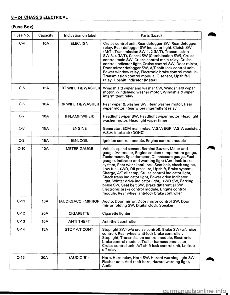
8-24 CHASSIS ELECTRICAL
(Fuse Box)
Fuse No.
Capacity Indication on label Parts (Load)
C-4 10A
ELEC.IGN. Cruise control unit, Rear defogger SW, Rear defogger
relay, Rear
defo9ger SW indicator light, Clutch SW
(M{T), Transmission SW-1, 2 (M!T), Transmission
SW-3, 4 (M{T), Cancel
SW (Combination SW), Cruise
control main
SW, Cruise control main relay, Cruise
control indicator light, Cruise control
SW, Door mirror,
Door mirror defogger SW, AfT shift lock control unit,
Power window relay, Electronic brake control module,
Transmission control module, G sensor, Upshift-2
relay, Upshift indicator (Meter)
C-5 15A FRTWIPER &WASHER
Windshield wipt~r and washer SW, Windshield wiper
motor, Windshit~ld washer motor, Windshield wiper
intermittent relay
C-6 10A RR WIPER & WASHER
Rear wiper & washer SW, Rear washer motor, Rear
wiper motor, Rear wiper intermittent relay
C-7 10A (H/LAMP WIPER) Headlight wiper SW, Headlight wiper motor, Headlight
washer motor, Headlight
wiper timer
C-8 15A ENGINE Generator, ECM main relay, V.S.V; EGA, V.S.V: canister,
V.S.V: intake air
(DOHC)
C-9 15A IGN. COIL Ignition control module, Engine control module
C-10 10A METER GAUGE Vehicle speed stmsor, Remind Buzzer, Meter and
gauge
(Voltmeter, Engine coolant temperature gauge,
Tachometer, Speedometer,
Oil pressure gauge, Fuel
gauge),
Indicator and warning light (Anti-lock brake
system, Rear wheel anti-lock, Seat belt, check engine,
Low fuel, 4WD,
Oil pressure, Upshift, Brake system,
Charge,
AfT oil temp, Cruise control indicator light,
Check trans indicator light,
Power drive indicator
light,
Winter drive indicator light), 4WD SW, Parking
brake SW, Seat belt SW, Brake differential SW
Electronic brake control module, Engine control
module, Rear wheel anti-lock brake controller
C-11 10A (AUDIO[ACCJ) MIRROR Audio, Door mirror, Door mirror control SW, Door
mirror folding SW, Digital clock, Speaker
C-12 20A CIGARETTE Cigarette lighter
C-13 10A
ANTI THEFT Anti-theft controller
C-14 15A
STOP AfT CONT Stoplight SW (w/o cruise control), Brake SW (w/cruise
control), Rear wheel anti-lock brake controller,
Stoplight, Transmission control module, Electronic
brake control module, Trailer harness connector,
Cruise control unit,
AfT shift lock control unit, Lockup
off relay
C-15
20A (AUDIO[B]) Horn,
Horn relay, Horn SW, Hazard warning light SW,
Flasher unit, Anti-theft horn, Hazard warning light,
Audio
•
Page 1215 of 1928
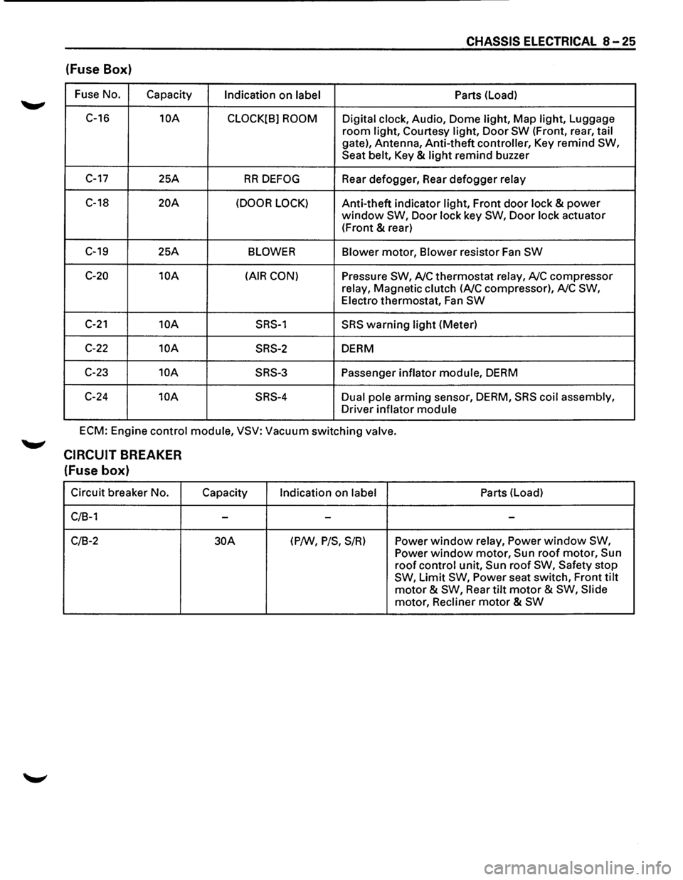
CHASSIS ELECTRICAL 8-25
(fuse Box)
Fuse No.
Capacity Indication on label Parts
(Load)
C-16
10A
CLOCK[B] ROOM Digital clock, Audio, Dome light, Map light, Luggage
room light, Courtesy light, Door SW (Front, rear, tail
gate), Antenna, Anti-theft controller, Key remind SW,
Seat belt, Key & light remind buzzer
C-17 25A RR DEFOG Rear defogger, Rear defogger relay
C-18 20A (DOOR LOCK) Anti-theft indicator light, Front door lock & power
window SW, Door lock key SW, Door lock actuator
(Front
& rear)
C-19 25A BLOWER Blower motor, Blower resistor Fan SW
C-20 10A (AIR CON) Pressure SW, A/C thermostat relay, A/C compressor
relay, Magnetic clutch
(A/C compressor), A/C SW,
Electro thermostat, Fan SW
C-21 10A SRS-1 SRS warning light (Meter)
C-22 10A SRS-2 DERM
C-23
10A SRS-3 Passenger inflator module, DERM
C-24
10A SRS-4 Dual pole arming sensor, DERM, SRS coil assembly,
Driver inflator module
ECM: Engine control module, VSV: Vacuum switching valve.
CIRCUIT BREAKER
(fuse box)
Circuit breaker No.
C/B-1
C/B-2
Capacity
-
30A
Indication on label
-
(P/W, P/S, S/R)
Parts (Load)
-
Power window relay, Power window SW,
Power window motor, Sun roof motor, Sun
roof control unit, Sun roof SW, Safety stop
SW, Limit SW, Power seat switch, Front tilt
motor & SW, Rear tilt motor & SW, Slide
motor, Recliner
motor & SW