relay ISUZU TROOPER 1995 Owner's Guide
[x] Cancel search | Manufacturer: ISUZU, Model Year: 1995, Model line: TROOPER, Model: ISUZU TROOPER 1995Pages: 1928
Page 436 of 1928
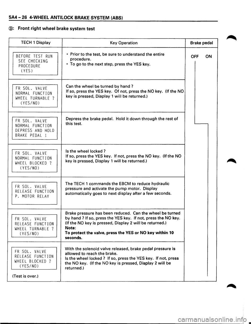
5A4-26 4-WHEEL ANTILOCK BRAKE SYSTEM (ABS)
@: Front right wheel brake system test
TECH 1 Display
Key Operation Brake pedal
BEFORE TEST RUN • Prior to the test, be sure to understand the entire OFF ON
SEE CHECKING procedure.
PROCEDURE • To go to the next step, press the YES key.
(YES)
FR SOL. VALVE Can the wheel be turned by hand ?
NORMAL FUNCTION If so, press the YES key. Of not, press the NO key. (If the NO
WHEEL TURNABLE ? key is pressed, Diaplay 1 will be returned.)
(YES/NO)
FR SOL. VALVE Depress the brake pedal. Hold it down through the rest of
NORMAL FUNCTION this test.
DEPRESS AND HOLD
BRAKE PEDAL !
FR SOL. VALVE Is the wheel locked ?
NORMAL FUNCTION If so, press the YES key. If not, press the NO key. (If the NO
WHEEL BLOCKED ? key is pressed, Display 1 will be returned.)
(YES/NO)
FR SOL. VALVE The TECH 1 commands the EBCM to reduce hydraulic
RELEASE FUNCTION pressure and activate the pump motor. Display
P. MOTOR RELAY automatically goes to next display after a few seconds.
Brake pressure has been reduced.
Can the wheel be turned
FR SOL. VALVE by hand? If so, press the YES key. If not, press the NO key.
RELEASE FUNCTION (If the NO key is pressed, Display 2 will be returned.)
WHEEL TURNABLE ? Note:
(YES/NO) To protect the valve, press the YES or NO key within 10
seconds.
FR SOL. VALVE With the solenoid valve released, brake pedal pressure is
RELEASE FUNCTION allowed to reach the brake.
WHEEL BLOCKED ? Is the wheel locked? If so, press the YES key. If not, press
(YES/NO) the NO key. (If the NO key is pressed, Display 2 will be
returned.)
(Test is over.)
•
Page 438 of 1928
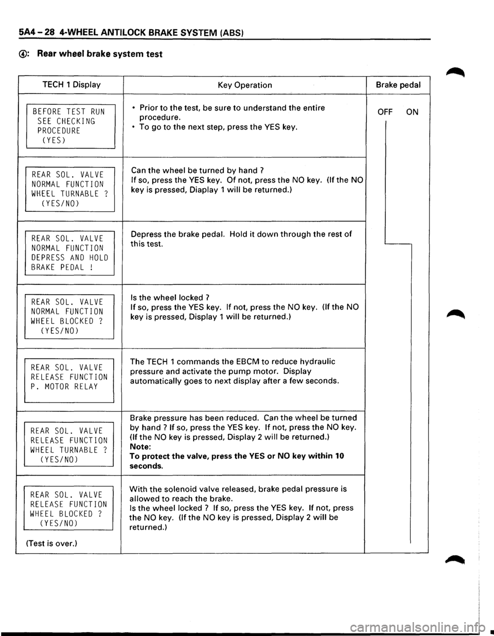
5A4-28 4-WHEEL ANTILOCK BRAKE SYSTEM (ABS)
@: Rear wheel brake system test
TECH 1 Display
Key Operation Brake
pedal
BEFORE TEST RUN • Prior to the test, be sure to understand the entire OFF ON
SEE CHECKING procedure.
PROCEDURE • To go to the next step, press the YES key.
(YES)
REAR SOL. VALVE Can the wheel be turned by hand ?
NORMAL FUNCTION If so, press the YES key. Of not, press the NO key. (If the NO
WHEEL TURNABLE ? key is pressed, Diaplay 1 will be returned.)
(YES/NO)
REAR SOL. VALVE Depress the brake pedal. Hold it down through the rest of
NORMAL FUNCTION this test.
DEPRESS AND HOLD
BRAKE PEDAL !
REAR SOL. VALVE Is the wheel locked ?
NORMAL FUNCTION If so, press the YES key. If not, press the NO key. Of the NO
WHEEL BLOCKED ? key is pressed, Display 1 will be returned.)
(YES/NO)
REAR SOL. VALVE The TECH 1 commands the EBCM to reduce hydraulic
RELEASE FUNCTION pressure and activate the pump motor. Display
P. MOTOR RELAY automatically goes to next display after a few seconds.
Brake pressure has been reduced. Can
the wheel be turned
REAR SOL. VALVE by hand ? If so, press the YES key. If not, press the NO key.
RELEASE FUNCTION (If the NO key is pressed, Display 2 will be returned.)
WHEEL TURNABLE ? Note:
(YES/NO) To protect the valve, press the YES or NO key within 10
seconds.
REAR SOL. VALVE With the solenoid valve released, brake pedal pressure is
RELEASE FUNCTION allowed to reach the brake.
WHEEL BLOCKED ? Is the wheel locked ? If so, press the YES key. If not, press
(YES/NO) the NO key. (If the NO key is pressed, Display 2 will be
returned.)
(Test is over.)
•
Page 443 of 1928
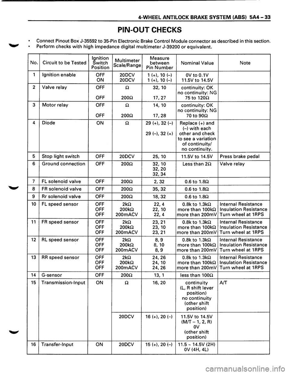
4-WHEEL ANTILOCK BRAKE SYSTEM (ABS) 5A4-33
PIN-OUT CHECKS
Connect Pinout Box J-35592 to 35-Pin Electronic Brake Control Module connector as described in this section.
~ Perform checks with high impedance digital multimeter J-39200 or equivalent.
Ignition
Multi meter Measure
No. Circuit to be Tested
Switch Scale/Range between Nominal Value Note Position
Pin Number
1 Ignition enable OFF 20DCV 1 (+), 10 (-) OV to 0.1V
ON 20DCV
1 (+), 10 (-) 11.5Vto 14.5V
2
Valve relay OFF n 32, 10 continuity: OK
no continuity: NG
OFF 200.Q 17,27 75 to 120n
3 Motor relay OFF n 14, 10 continuity: OK
no continuity: NG
OFF 200Q 17,28 70 to 90n
4
Diode ON n 29 (+), 32 (-) Replace(+) and
(-)with each
29 (-), 32 (+) other and check
to see a variation
of continuity/
no continuity.
5
Stop light switch OFF 20DCV 25, 10 11.5V to 14.5V Press brake pedal
6 Ground connection OFF 200Q 32, 10 Less than 2.Q Valve relay
32,20
32,34
7 FL solenoid valve OFF 200Q 2,32 0.6 to 1.8Q
8 FR solenoid valve OFF 200Q 35,32 0.6 to 1.8n
9 Rr solenoid valve OFF 200Q 18,32 0.6 to 1.8n
10 FL speed sensor OFF 2k.Q 22,4 0.8k to 1.3kn Internal Resistance
OFF 200k.Q 22, 10 more than 100kn Insulation Resistance
OFF 200mACV 22,4 more than 200mV Turn wheel at 1RPS
11 FR speed
sensor OFF 2k.Q 23,21 0.8k to 1.3k.Q Internal Resistance
OFF 200k.Q 23, 10 more than 100k.Q Insulation Resistance
OFF 200mACV 23,21 more than 200mV Turn wheel at 1RPS
12 RL speed sensor OFF 2k.Q 8,9 0.8k to 1.3k.Q Internal Resistance
OFF 200k.Q 8, 10 more than 100k.Q Insulation Resistance
OFF 200mACV 8,9 more than 200mV Turn wheel at 1RPS
13 RR speed sensor OFF 2k.Q 24,26 0.8k to 1.3k.Q Internal Resistance
OFF 200k.Q 24, 10 more than 100k.Q Insulation Resistance
OFF 200mACV 24,26 more than 200mV Turn wheel at 1RPS
14 G-sensor OFF 200.Q 13, 1 less than 100n
15 Transmission-Input ON n 16,20 continuity A/T
(L, R shift lever
position)
no
continuity
(other shift
position)
20DCV 16 (+), 20 (-) 11.5V to 14.5V
(M/T-1, 2, R)
ov
(other shift
position)
16 Transfer-Input ON 20DCV 15 (+), 20 (-) 11.5-14.5V (2H)
OV (4H, 4L)
Page 447 of 1928
!! co U1 )> "" I .... w
(
EBCM
RR
ABS SPEED SENSOR
(RHl
.
RELAY:
UPSHIFT-2
""·,'-....."
M-11_
. ·r·---
..
C-39
M-12"-~.·
··..
> .. , ,·
~'
...
,
~~~~~
~.-·
& FUSE
BOX
· ••.
(FL-1,
FL-2, FL-6,
F-9~
'•
BATTERY HYDRAULIC
--+1--.-.
UNIT
C-33
--~----
C-34.
H-41
H-42
TRANSMISSION
(
~·~ rl r
( STARTER
SW
RR
ABS SPEED SENSOR
(LH)
\~· \'
-.
.
B-46
' G SENSOR
\
FUSE
BOX (C-3, C-4, C-10, C-14)
BRAKE
SW
(W/CRUISE CONTROL)
STOPLIGHT SW
(W/0
CRUISE CONTROL)
BRAKE PEDAL FRT
ABS
SPEED SENSOR
(LH)
(
"V )> ~ r-0 s 5 2
.... :e ::I: m
m r-l> 2 ~ r-0 0 ~ CCI ~ ~ m ~ Cl) -t m s: ~ ~ c.n t I w .....
Page 459 of 1928
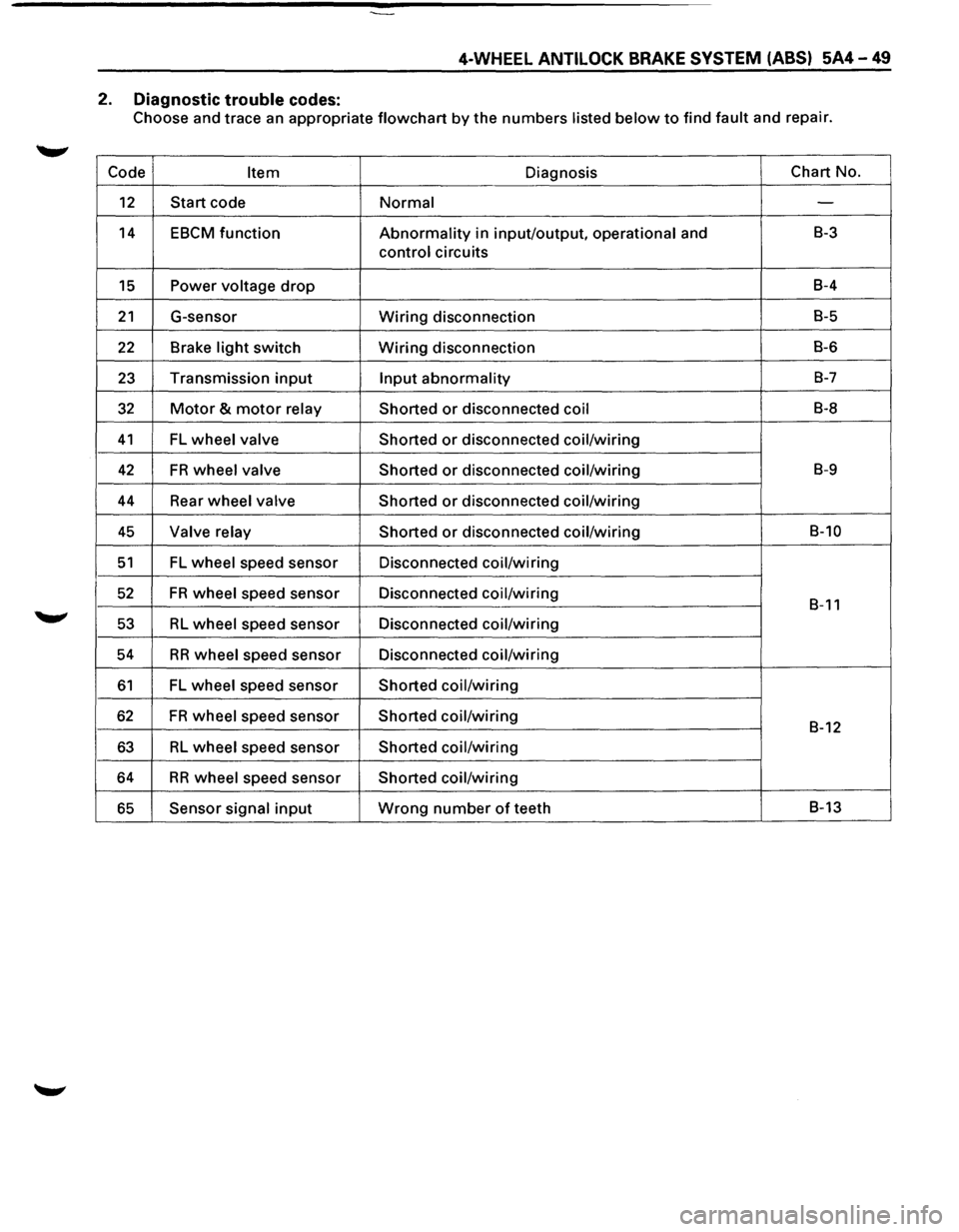
4-WHEEL ANTILOCK BRAKE SYSTEM (ABS) 5A4-49
2. Diagnostic trouble codes:
Choose and trace an appropriate flowchart by the numbers listed below to find fault and repair.
Code
Item Diagnosis Chart
No.
12 Start code Normal -
14 EBCM function Abnormality in input/output, operational and B-3
control circuits
15 Power voltage drop B-4
21 G-sensor Wiring disconnection B-5
22 Brake light switch Wiring disconnection B-6
23 Transmission input Input abnormality B-7
32 Motor & motor relay
Shorted or disconnected coil B-8
41 FL wheel valve
Shorted or disconnected coil/wiring
42 FR wheel valve
Shorted or disconnected coil/wiring B-9
44 Rear wheel valve Shorted or disconnected coil/wiring
45 Valve relay Shorted or disconnected coil/wiring B-10
51 FL wheel speed sensor Disconnected coil/wiring
52 FR wheel speed sensor Disconnected coil/wiring B-11
53 RL wheel speed sensor Disconnected coil/wiring
54
RR wheel speed sensor Disconnected coil/wiring
61 FL wheel speed sensor Shorted coil/wiring
62 FR wheel speed sensor Shorted coil/wiring B-12
63 RL wheel speed sensor Shorted coil/wiring
64 RR wheel speed sensor Shorted coil/wiring
65 Sensor signal input Wrong number of teeth B-13
Page 468 of 1928
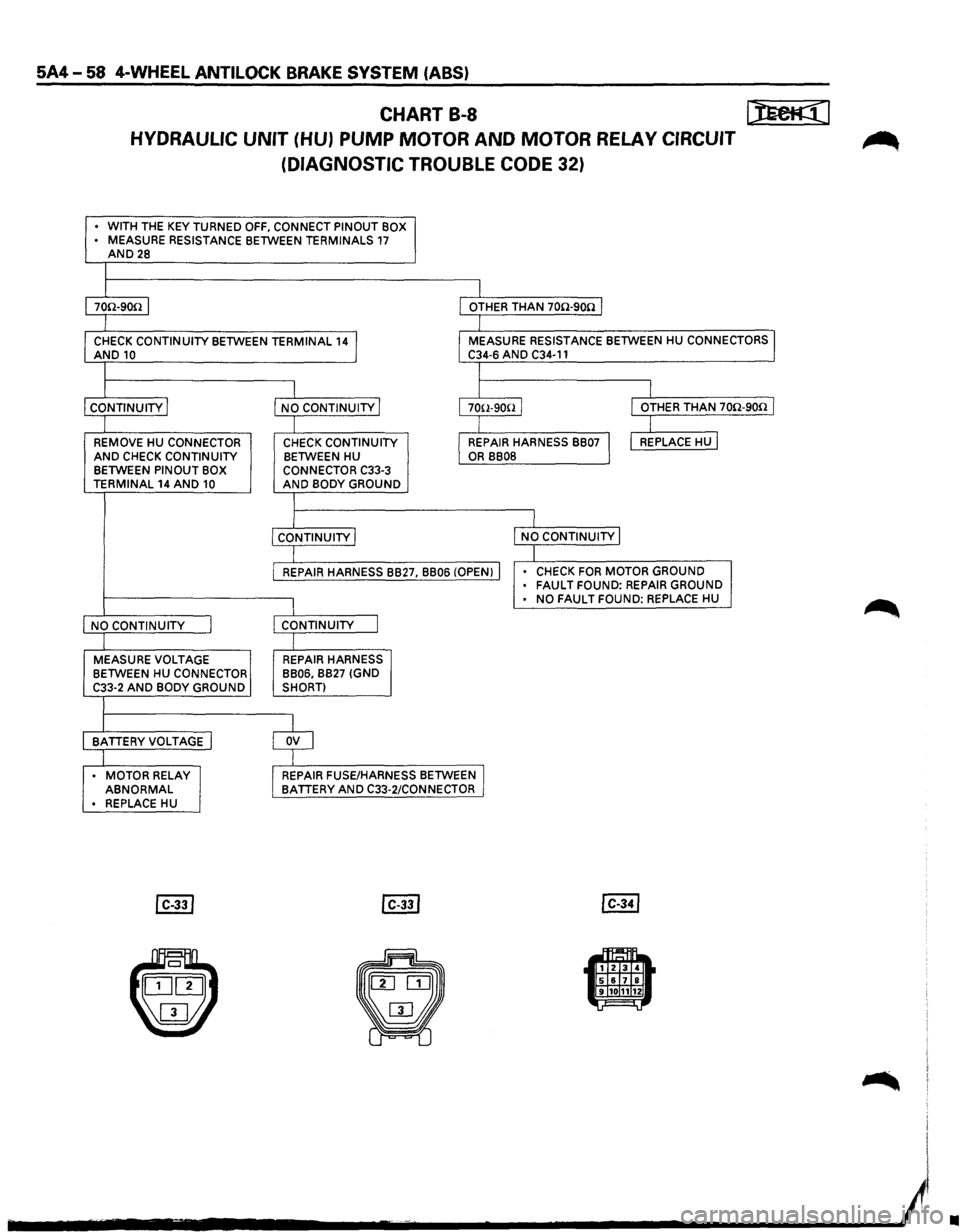
5A4-58 4-WHEEL ANTILOCK BRAKE SYSTEM (ABS)
CHART B-8 I):Eeti((l
HYDRAULIC UNIT (HU) PUMP MOTOR AND MOTOR RELAY CIRCUIT ~
(DIAGNOSTIC TROUBLE CODE 32)
• WITH THE KEY TURNED OFF, CONNECT PINOUT BOX
• MEASURE RESISTANCE BETWEEN TERMINALS 17 AND28
I 70n-9on I I OTHER THAN 70n-9on I
I
CHECK CONTINUITY BETWEEN TERMINAL 141 AND10 I MEASURE RESISTANCE BETWEEN HU CONNECTORS I C34-6 AND C34-11
I
I I I
CONTINUITY j NO CONTINUITY j 1 70(l-9ooJ I OTHER THAN 70n-9on I
I I I REMOVE HU CONNECTOR CHECK CONTINUITY I REPAIR HARNESS BB07 I I REPLACE HU I AND CHECK CONTINUITY BETWEEN HU OR BB08 BETWEEN PINOUT BOX
CONNECTOR C33-3 TERMINAL 14 AND 10 AND BODY GROUND
I
I
I CONTINUITY I NO CONTINUITY j
I I REPAIR HARNESS BB27, BB06 (OPEN) I • CHECK FOR MOTOR GROUND • FAULT FOUND: REPAIR GROUND
I • NO FAULT FOUND: REPLACE HU
NO CONTINUITY I CONTINUITY J
I MEASURE VOLTAGE REPAIR HARNESS
BETWEEN HU CONNECTOR BB06, BB27
(GND
C33-2 AND BODY GROUND SHORT)
BATTERYVOLTAGE I $
. MOTOR RELAY REPAIR FUSE/HARNESS BETWEEN I ABNORMAL BATTERY AND C33-2/CONNECTOR • REPLACE HU
•
Page 470 of 1928
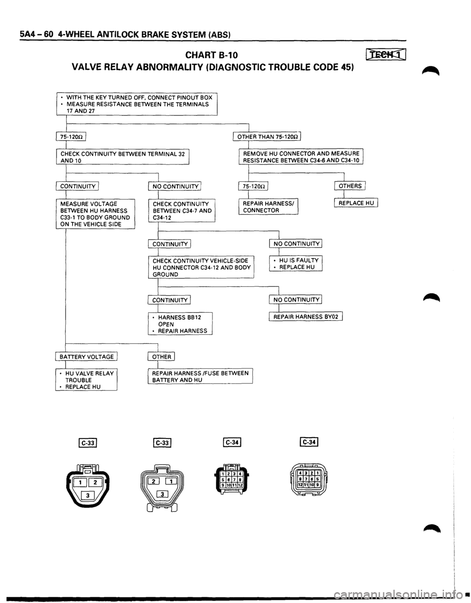
5A4-60 4-WHEEL ANTILOCK BRAKE SYSTEM (ABS)
CHART B-1 0 [):Ee@]
VALVE RELAY ABNORMALITY (DIAGNOSTIC TROUBLE CODE 45) ~
• WITH THE KEY TURNED OFF, CONNECT PINOUT BOX
• MEASURE RESISTANCE BETWEEN THE TERMINALS 17 AND 27
I 1s-12oo 1 I OTHER THAN 75-1200 J
I
CHECK CONTINUITY
BETWEEN TERMINAL 32 J AND10 I_ REMOVE HU CONNECTOR AND MEASURE I RESISTANCE BETWEEN C34-6 AND C34-10
I
I
I I
CONTINUITY I
NO CONTINUITY/ I75-120n/ I OTHERS I
I I
I
MEASURE
VOLTAGE CHECK CONTINUITY I REPAIR HARNESS/ J I REPLACE HU I
BETWEEN HU HARNESS BETWEEN C34-7 AND CONNECTOR
C33-1 TO BODY GROUND C34-12 ON THE VEHICLE SIDE I
I I CONTINUITY I l NO CONTINUITY I
I I
CHECK CONTINUITY VEHICLE-SIDE
,. HU IS FAULTY J HU CONNECTOR C34-12 AND BODY • REPLACE
HU GROUND
I
I I
CONTINUITY j I NO CONTINUITY I
I I • HARNESS BB12 l REPAIR HARNESS BY02 I OPEN
• REPAIR HARNESS
I BATTERY VOLTAGE j OTHER I
I
• HU VALVE RELAY I REPAIR HARNESS /FUSE BETWEEN I TROUBLE BATTERY AND HU • REPLACE HU
~1111 .. 1 2 3 4 5 617 8 9 101112 =
•
Page 502 of 1928
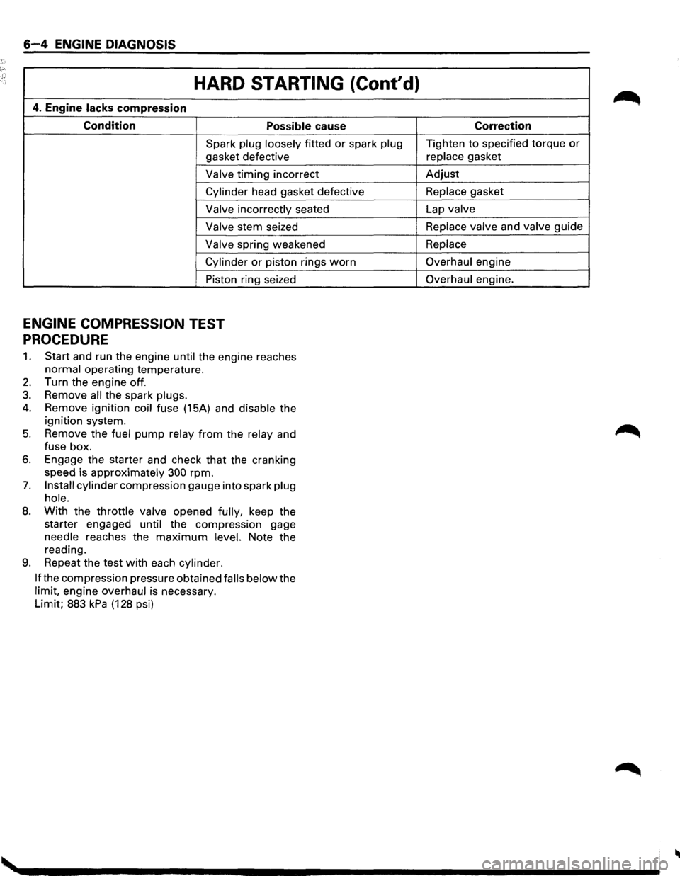
6-4 ENGINE DIAGNOSIS
HARD STARTING (Cont'd)
4. Engine lacks compression
Condition Possible cause
Spark plug loosely fitted or spark plug
gasket defective
Valve timing incorrect
Cylinder head gasket defective
Valve incorrectly seated
Valve stem seized
Valve spring weakened
Cylinder or piston rings worn
Piston ring seized
ENGINE COMPRESSION TEST
PROCEDURE
1. Start and run the engine until the engine reaches
normal operating temperature.
2. Turn the engine off.
3. Remove all the spark plugs.
4. Remove ignition coil fuse (15A) and disable the
ignition system.
5. Remove the fuel pump relay from the relay and
fuse box.
6. Engage the starter and check that the cranking
speed is approximately
300 rpm.
7. Install cylinder compression gauge into spark plug
hole.
8. With the throttle valve opened fully, keep the
starter engaged
until the compression gage
needle reaches the
maximum level. Note the
reading.
9. Repeat the test with each cylinder.
If
the compression pressure obtained falls below the
limit, engine overhaul is necessary.
Limit; 883
kPa (128 psi) Correction
Tighten
to specified torque or
replace gasket
Adjust
Replace gasket
Lap
valve
Replace valve
and valve guide
Replace
Overhaul engine
Overhaul engine.
Page 503 of 1928
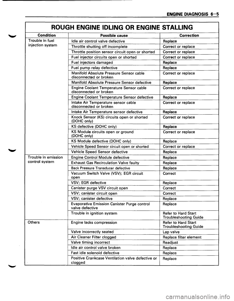
ENGINE DIAGNOSIS 6-5
ROUGH ENGINE IDLING OR ENGINE STALLING
Condition Possible cause Correction
Trouble in fuel
Idle air control valve defective Replace
injection system
Throttle shutting
off incomplete Correct or replace
Throttle position sensor circuit open
or shorted Correct or replace
Fuel injector circuits open or shorted Correct or replace
Fuel injectors damaged
Replace
Fuel pump relay defective Replace
Manifold Absolute Pressure Sensor
cable Correct or replace
disconnected
or broken
Manifold Absolute Pressure Sensor defective
Replace
Engine Coolant Temperature Sensor cable Correct
or replace
disconnected
or broken
Engine Coolant Temperature Sensor defective
Replace
Intake Air Temperature sensor cable Correct or replace
disconnected
or broken
Intake Air Temperature sensor defective
Replace
Knock Sensor
(KS) circuits open or shorted
Correct or replace
(DOHC only)
KS defective (DOHC only) Replace
KS Module circuits open or ground
Correct or replace
(DOHC only)
KS Module defective (DOHC only) Replace
Vehicle Speed Sensor circuit open or shorted
Correct or replace
Vehicle Speed Sensor defective
Replace
Trouble in emission
Engine Control Module defective
Replace
control system
Exhaust Gas Recirculation
Valve faulty
Replace
Back Pressure Transducer defective
Replace
Vacuum Switch Valve (VSV); EGR circuit
Correct
open
VSV; EGR defective Replace
Canister purge
VSV circuit open
Correct
VSV; canister circuit open
Correct
VSV; canister defective
Replace
Evaporative Emission Canister Purge control
Replace
valve defective
Trouble in ignition system
Refer
to Hard Start
Troubleshooting Guide
Others Engine lacks compression
Refer to Hard Start
Troubleshooting Guide
Valve incorrectly seated
Lap valve
Air Cleaner Filter clogged
Replace filter element
Valve timing incorrect
Readjust
Idle air control valve broken
Replace
Fast
idle solenoid defective
Replace
Positive Crankcase Ventilation valve defective
or Replace
clogged
Page 510 of 1928
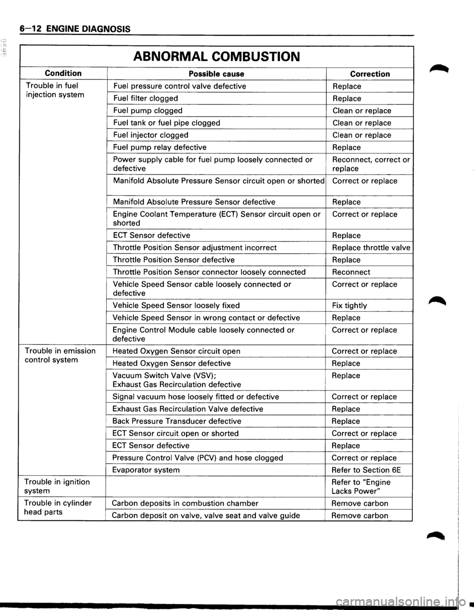
6-12 ENGINE DIAGNOSIS
ABNORMAL COMBUSTION
Condition
Possible cause Correction
Trouble in fuel Fuel pressure control valve defective Replace
injection system
Fuel filter clogged
Replace
Fuel pump clogged Clean or replace
Fuel tank
or fuel pipe clogged Clean or replace
Fuel injector clogged Clean or replace
Fuel
pump relay defective
Replace
Power supply cable for fuel pump loosely connected or Reconnect, correct or
defective
replace
Manifold Absolute
Pressure Sensor circuit open or shorted Correct or replace
Manifold Absolute
Pressure Sensor defective Replace
Engine Coolant Temperature
(ECT) Sensor circuit open or Correct or replace
shorted
ECT Sensor defective
Replace
Throttle
Position Sensor adjustment incorrect Replace throttle valve
Throttle
Position Sensor defective
Replace
Throttle
Position Sensor connector loosely connected Reconnect
Vehicle Speed Sensor cable loosely connected or Correct or replace
defective
Vehicle Speed Sensor loosely fixed Fix tightly
Vehicle Speed Sensor in wrong contact or defective Replace
Engine Control Module cable
loosely connected or Correct or replace
defective
Trouble in emission
Heated
Oxygen Sensor circuit open Correct or replace
control system
Heated
Oxygen Sensor defective Replace
Vacuum Switch
Valve (VSV); Replace
Exhaust Gas Recirculation defective
Signal vacuum hose loosely fitted or defective Correct or replace
Exhaust Gas Recirculation
Valve defective Replace
Back
Pressure Transducer defective Replace
ECT Sensor circuit open or shorted Correct or replace
ECT Sensor defective Replace
Pressure Control Valve (PCV) and hose clogged Correct or replace
Evaporator system
Refer
to Section 6E
Trouble in ignition
Refer to "Engine
system Lacks
Power"
Trouble in cylinder
Carbon deposits in combustion chamber Remove carbon
head parts
Carbon deposit on valve,
valve seat and valve guide
Remove carbon
•