relay ISUZU TROOPER 1995 User Guide
[x] Cancel search | Manufacturer: ISUZU, Model Year: 1995, Model line: TROOPER, Model: ISUZU TROOPER 1995Pages: 1928
Page 72 of 1928
18-18 AIR CONDITIONING
~ INDIVIDUAL INSPECTION
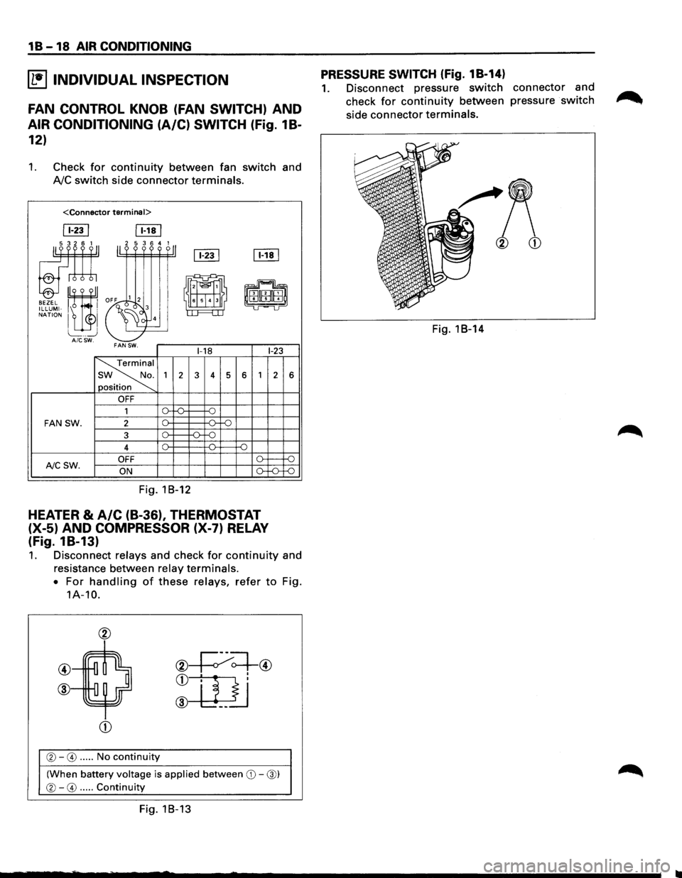
FAN CONTROL KNOB (FAN SWITCH) AND
AIR CONDITIONING (A/C) SWITCH (fig. 1 B-
12)
1. Check for continuity between fan switch and
AJC switch side connector terminals.
ITill [Eill
[fill [Eill ~ 11''''''·11
'"" ~~ -
-~
i'~EHffil ILLUMI-, . cl 3 LI LJ NATION I I 4
L_ _ _j AICSW. FAN SW. 1-18 1-23
~
1
2 3 4 5 6 1 2
n
.
OFF
1 0
FAN SW. 2 [)_ -11--::=:;-
3 o-~ -n. -o
4 [)_ -o
OFF (). f--NCSW. ON [)_
Fig. 18-12
HEATER & A/C (B-36), THERMOSTAT
(X-5) AND COMPRESSOR (X-7) RELAY
(fig. 18-13)
:;,_
6
-f)
-:;::;
1. Disconnect relays and check for continuity and
resistance between
relay terminals.
•
For handling of these relays, refer to Fig.
1A-10.
@
@
®
CD
®-0 ..... No continuity
(When battery voltage is applied between CD-@)
®-0 ..... Continuity
Fig. 18-13
PRESSURE SWITCH (Fig. 18-14)
1. Disconnect pressure switch connector and
check
for continuity between pressure switch
side connector terminals.
Fig. 18-14
Page 135 of 1928
FRONT END ALIGNMENT 3A-3
ON-VEHICLE SERVICE
INSPECTION
Before making any adjustments affecting caster,
camber or toe-in, the following front end inspection
should be made.
I L•IINSPECT
1. Tires for proper inflation pressure. Refer to
"Wheels and Tires" in section 3E.
2. Front wheel bearings for proper adjustment.
Refer to "Front Wheel Drive" in section 4C.
3. Ball joints, tie rod ends and relay rods. If
excessive looseness is noted, correct before
adjusting. Refer
to "Steering Linkage" in section
3B3.
4. Wheel and tires for run-out. Refer to "Wheels
and Tires" in section 3E.
5. Trim height. If not within specifications, the
correction
must be made before adjusting caster.
6. Steering gear for looseness at the frame.
7. Shock absorbers for leaks or any noticeable
noise.
Refer
to "Front Suspension" in section 3C.
8. Control arms or stabilizer bar attachment for
looseness. Refer to "Front Suspension" in section
3C.
9. Alignment equipment. Follow the manufacturer's
instructions.
10. Level of the vehicle. The vehicle must be on a
level surface.
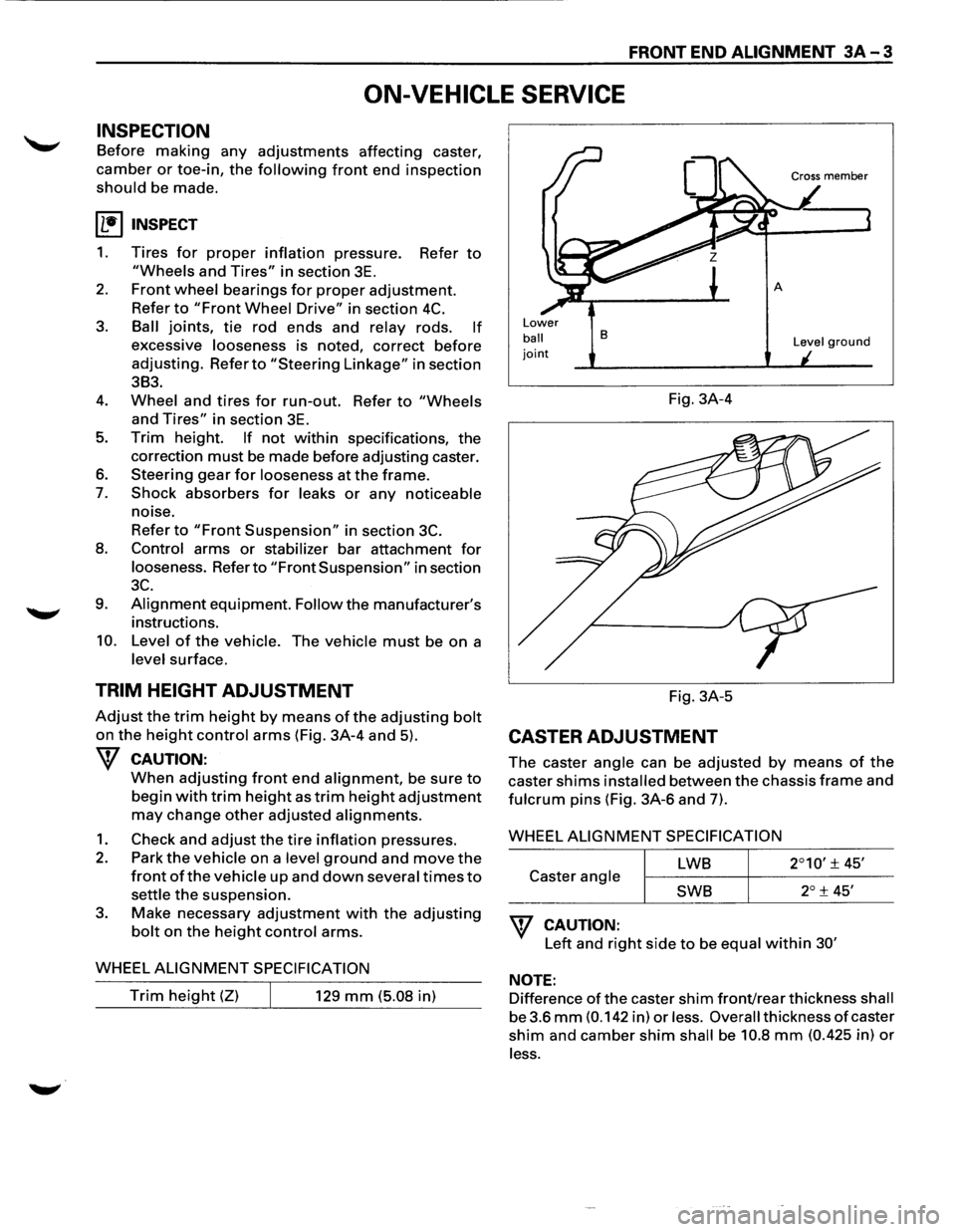
TRIM HEIGHT ADJUSTMENT
Adjust the trim height by means of the adjusting bolt
on the height control arms (Fig. 3A-4 and 5).
W CAUTION:
When adjusting front end alignment, be sure to
begin with trim height as trim height adjustment
may change other adjusted alignments.
1. Check and adjust the tire inflation pressures.
2. Park the vehicle on a level ground and move the
front of the vehicle up and down several times to
settle the suspension.
3. Make necessary adjustment with the adjusting
bolt on the height control arms.
WHEEL
ALIGNMENT SPECIFICATION
Trim height (Z) 129 mm (5.08 in)
Lower
ball joint
B
Fig. 3A-4
Fig. 3A-5
CASTER ADJUSTMENT
Level ground
The caster angle can be adjusted by means of the
caster shims installed between the chassis frame and
fulcrum pins (Fig. 3A-6 and 7).
WHEEL
ALIGNMENT SPECIFICATION
LWB
Caster angle
SWB
W CAUTION:
Left and right side to be equal within 30'
NOTE:
Difference of the caster shim front/rear thickness shall
be 3.6
mm (0.142 in) or less. Overall thickness of caster
shim and camber shim shall be 10.8 mm (0.425 in) or
less.
Page 137 of 1928
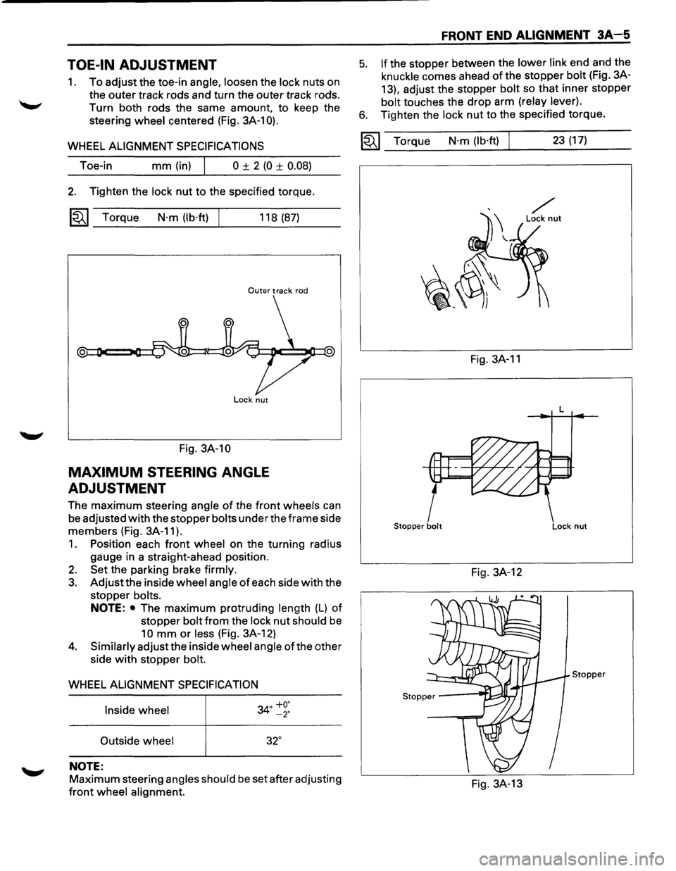
TOE-IN ADJUSTMENT
1. To adjust the toe-in angle, loosen the lock nuts on
the outer track rods and turn the outer track rods.
Turn both rods the same amount, to keep the
steering
wheel centered (Fig. 3A-1 0).
WHEEL ALIGNMENT SPECIFICATIONS
Toe-in mm (in) I 0 ± 2 (0 ± 0.08)
2. Tighten the lock nut to the specified torque.
~~~ Torque N·m (lb·ft) 118 (87)
Outer track rod
Lock nut
Fig. 3A-10
MAXIMUM STEERING ANGLE
ADJUSTMENT
The maximum steering angle of the front wheels can
be adjusted
with the stopper bolts under the frame side
members (Fig. 3A-11 ).
1. Position each front wheel on the turning radius
gauge in a straight-ahead position.
2. Set the parking brake firmly.
3. Adjust the inside wheel angle of each side with the
stopper
bolts.
NOTE: • The maximum protruding length (L) of
stopper bolt from the lock nut should be
10 mm or less (Fig. 3A-12)
4. Similarly adjust the inside wheel angle of the other
side
with stopper bolt.
WHEEL ALIGNMENT SPECIFICATION
Inside wheel
34° ~~:
Outside wheel 32°
NOTE:
Maximum steering angles should be set after adjusting
front wheel alignment.
FRONT END ALIGNMENT 3A-5
5. If the stopper between the lower link end and the
knuckle comes ahead of the stopper bolt (Fig. 3A-
13), adjust the stopper
bolt so that inner stopper
bolt touches the drop arm (relay lever).
6. Tighten the lock nut to the specified torque.
~~~ Torque N·m (lb·ft) 23 (17)
Fig. 3A-11
L
Stopper bolt Lock nut
Fig. 3A-12
Stopper
Fig. 3A-13
Page 157 of 1928
STEERING LINKAGE 383-1
SECTION 383
STEERING LINKAGE
w CAUTION:
• When fasteners are removed, always reinstall them at the same location from which they were removed. If a
fastener needs
to be replaced, use the correct part number fastener for that application. If the correct part
number fastener is not available, a fastener of equal size and strength (or stronger) may be used. Fasteners
that are not reused, and those requiring thread locking compound, will be called out. The correct torque
value must be used when installing fasteners that require it. If the above conditions are not followed, parts or
system damage could result.
CONTENTS
General Description . . . . . . . . . . . . . . . . . . . . 383-1
On-Vehicle Service .................... 383-2
Center Track Rod Assembly . . . . . . . . . . . 383-2
Outer Track Rod Assembly . . . . . . . . . . . . 383-4
Relay Lever . . . . . . . . . . . . . . . . . . . . . . . . . 383-6 Main
Data
and Specifications ............ 383-8
Torque Specifications
................ 383-8
Special Tools .......................... 383-8
GENERAL DESCRIPTION
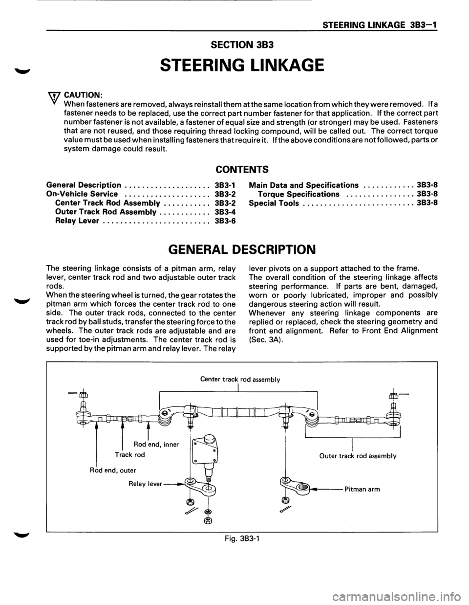
The steering linkage consists of a pitman arm, relay
lever,
center track rod and two adjustable outer track
rods.
When the steering
wheel is turned, the gear rotates the
pitman arm
which forces the center track rod to one
side. The outer track rods, connected to the center
track rod
by ball studs, transfer the steering force to the
wheels. The outer track rods are adjustable and are
used
for toe-in adjustments. The center track rod is
supported
by the pitman arm and relay lever. The relay lever
pivots
on a support attached to the frame.
The
overall condition of the steering linkage affects
steering performance.
If parts are bent, damaged,
worn or poorly lubricated, improper and possibly
dangerous steering action will result.
Whenever any steering linkage components are
replied or replaced, check the steering geometry and
front end alignment. Refer to Front End Alignment
(Sec. 3A).
Center track rod assembly
Rod end, inner
Track rod
Rod end, outer
Relay lever---~·--:;:::jo
I
I Outer track rod assembly
Fig. 383-1
Page 158 of 1928
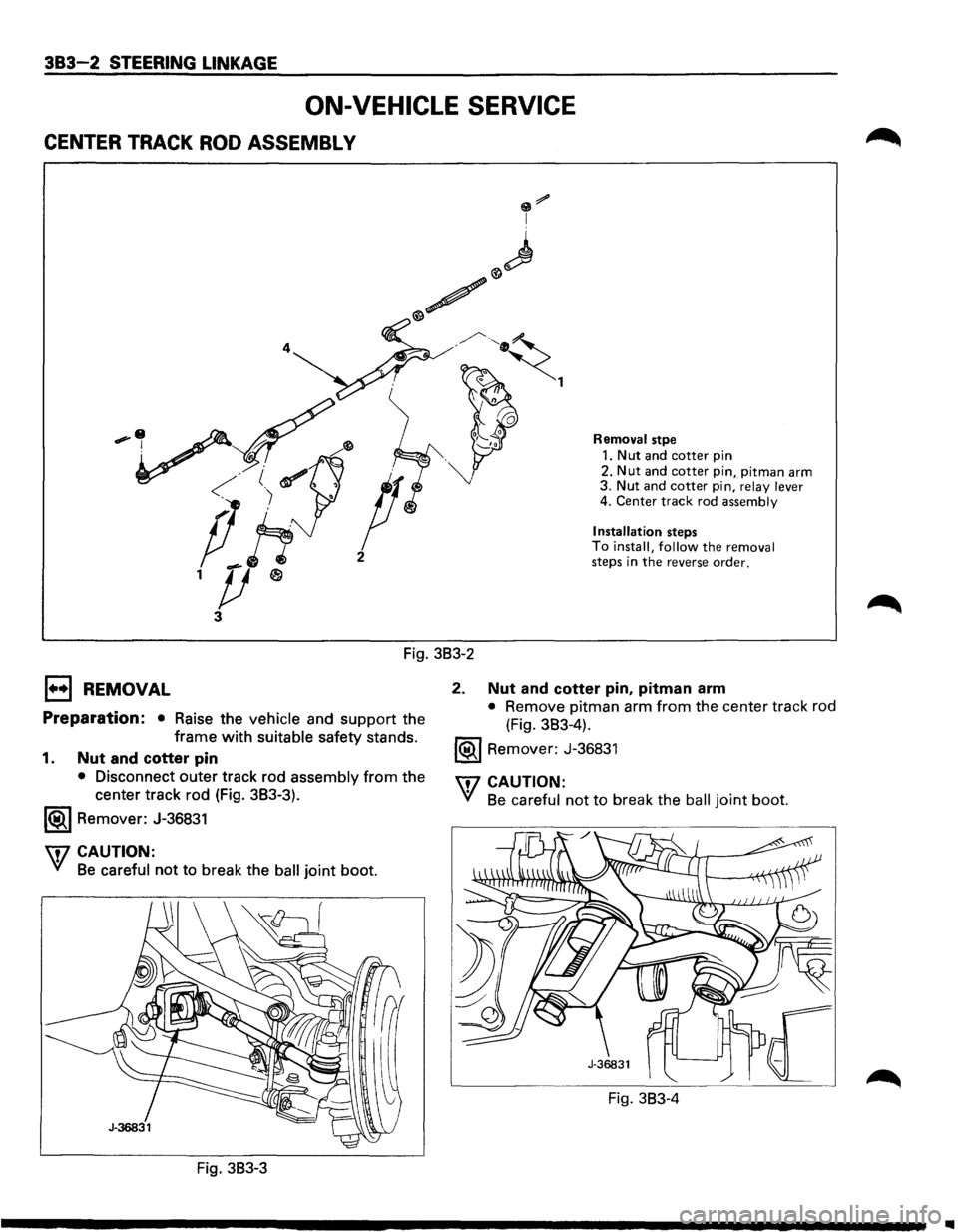
383-2 STEERING LINKAGE
ON-VEHICLE SERVICE
CENTER TRACK ROD ASSEMBL V
Removal stpe
1. Nut and cotter pin
2.
Nut and cotter pin, pitman arm 3. Nut and cotter pin, relay lever 4. Center track rod assembly
Installation
steps To install, follow the removal steps in the reverse order.
Fig. 3B3-2
1••1 REMOVAL
Preparation: • Raise the vehicle and support the
frame
with suitable safety stands.
1. Nut and cotter pin
• Disconnect outer track rod assembly from the
center track rod (Fig. 3B3-3).
1®.1 Remover: J-36831
U7 CAUTION:
V/ Be careful not to break the ball joint boot.
Fig. 3B3-3
2. Nut and cotter pin, pitman arm
• Remove pitman arm from the center track rod
(Fig. 3B3-4).
1®1 Remover: J-36831
\f7 CAUTION:
VI Be careful not to break the ball joint boot.
Fig. 3B3-4
..
Page 159 of 1928
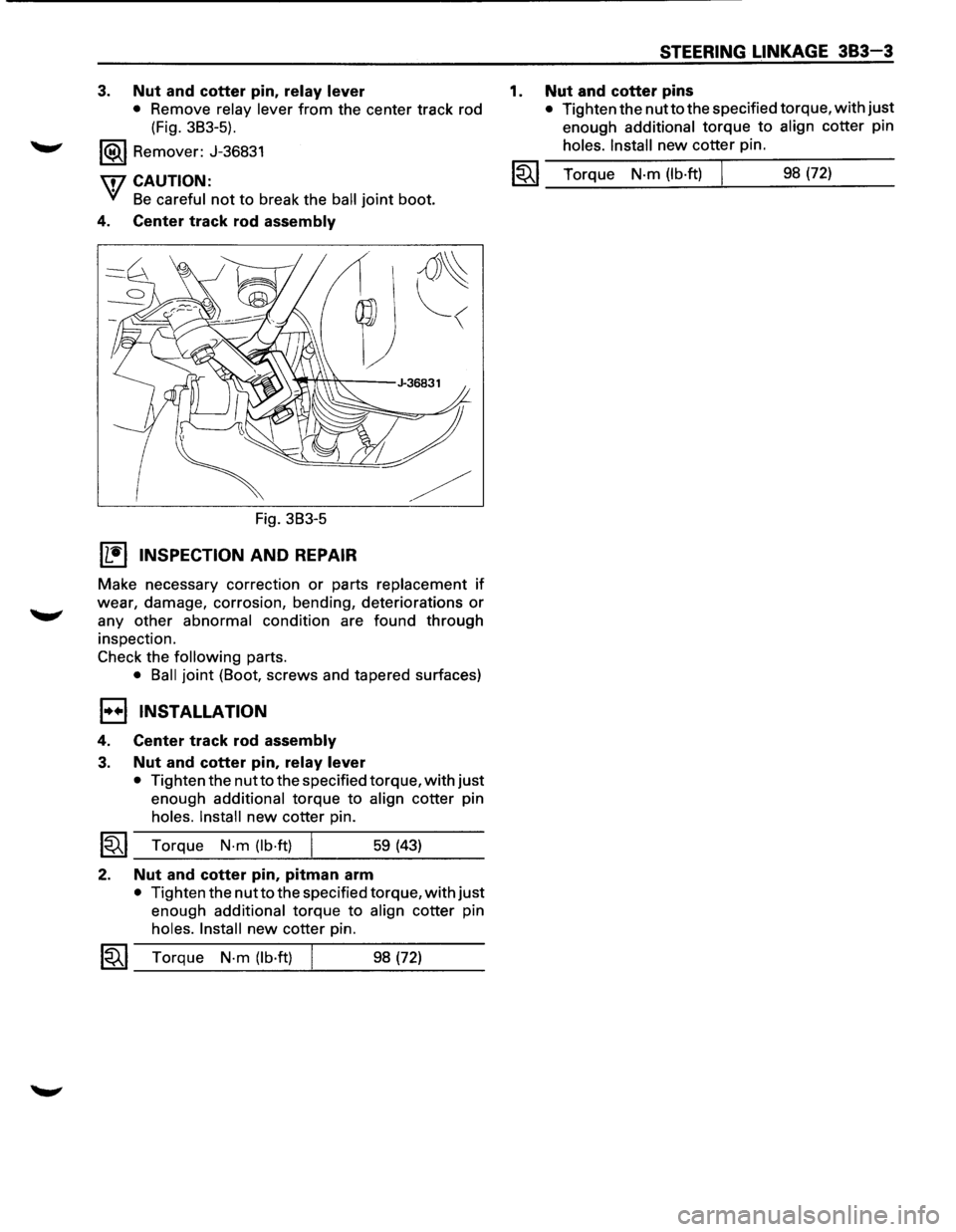
3. Nut and cotter pin, relay lever
• Remove relay lever from the center track rod
(Fig. 3B3-5).
1®.1 Remover: J-36831
\flCAUTION:
'VI Be careful not to break the ball joint boot.
4. Center track rod assembly
Fig. 3B3-5
Wtl INSPECTION AND REPAIR
~
Make necessary correction or parts replacement if
wear, damage, corrosion, bending, deteriorations or
any other abnormal condition are found through
inspection.
Check the
following parts.
• Ball joint (Boot, screws and tapered surfaces)
1••1 INSTALLATION
4. Center track rod assembly
3. Nut and cotter pin, relay lever
• Tighten the nutto the specified torque, with just
enough additional torque to align cotter pin
holes. Install new cotter pin.
~~~ Torque N·m (lb·ft) 59 (43)
2. Nut and cotter pin, pitman arm
• Tighten the nut to the specified torque, with just
enough additional torque to align cotter pin
holes. Install new cotter pin.
1~1 Torque N-m (lb·ft) 98 (72)
1.
STEERING LINKAGE 383-3
Nut and cotter pins
• Tighten the nutto the specified torque, with just
enough
additional torque to align cotter pin
holes. Install new cotter pin.
I~I_T_o_rq..;...u_e_N_·m_(l_b_·ft_) ___t_ ___ 9_8_(7_2_) __ _
Page 162 of 1928
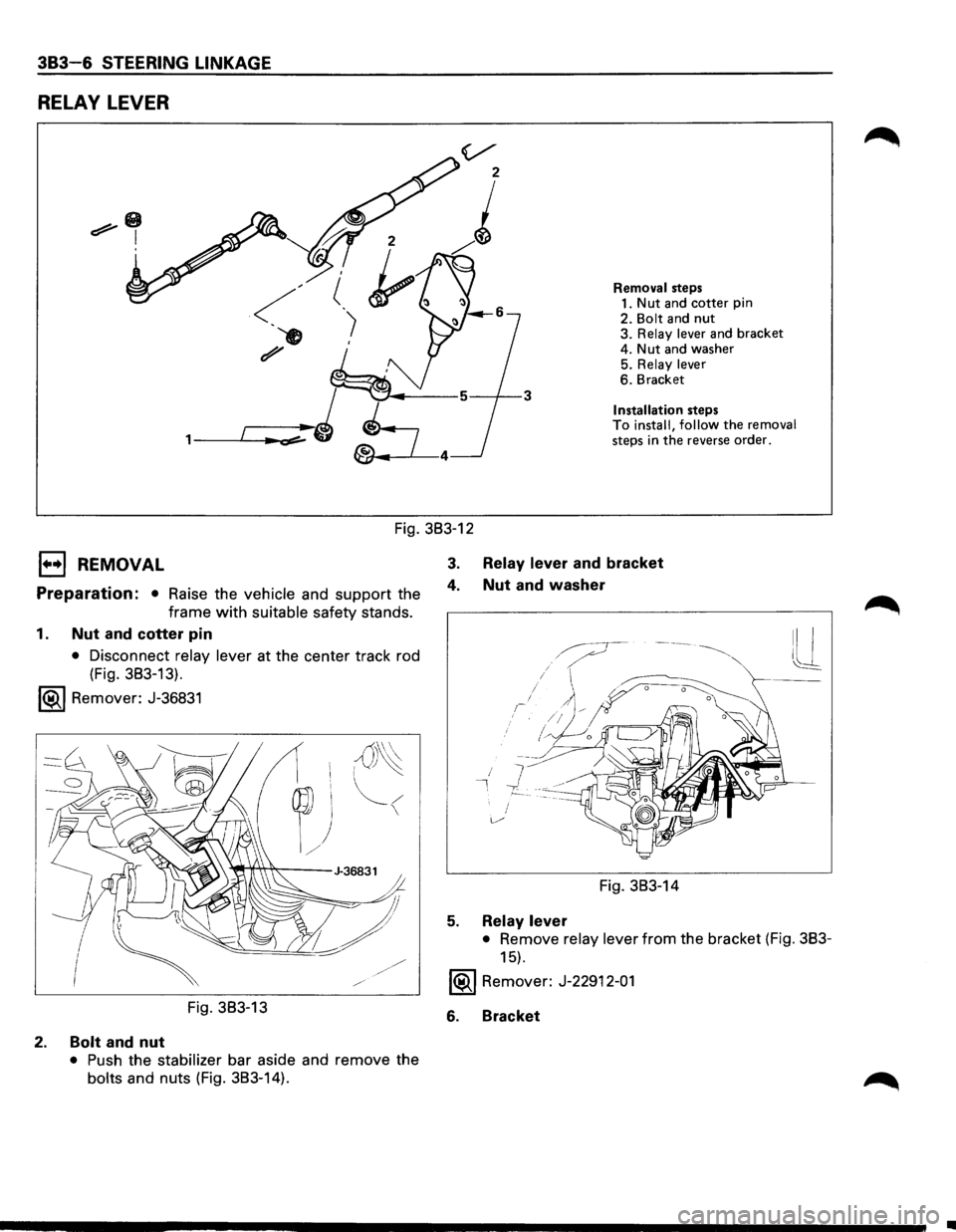
383-6 STEERING LINKAGE
RELAY LEVER
v
'
z
)
'
Removal steps
1. Nut and cotter pin
2. Bolt and nut 3. Relay lever and bracket
~
, __ ,.___ ... ~:;r:=--~J L •--~---3
4. Nut and washer
5. Relay lever 6. Bracket
Installation steps
®--L---4
To install, follow the removal steps in the reverse order.
Fig. 383-12
EJ REMOVAL
Preparation: • Raise the vehicle and support the
frame with suitable safety stands.
1. Nut and cotter pin
• Disconnect relay lever at the center track rod
(Fig. 383-13).
1®..1 Remover: J-36831
Fig. 383-13
2. Bolt and nut
• Push the stabilizer bar aside and remove the
bolts and nuts (Fig. 383-14).
3. Relay lever and bracket
4. Nut and washer
7 I, -y
Fig. 383-14
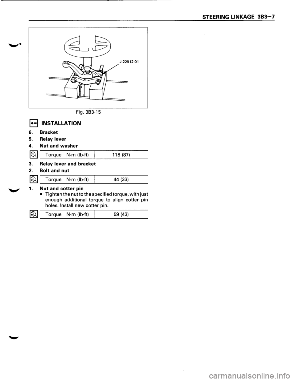
5. Relay lever
• Remove relay lever from the bracket (Fig. 383-
15).
1®..1 Remover: J-22912-01
6. Bracket
..
Page 163 of 1928
STEERING LINKAGE 383-7
J-22912·01
Fig. 383-15
E1 INSTALLATION
6. Bracket
5. Relay lever
4. Nut and washer
~ Torque N·m (lb·ft) 118 (87)
3. Relay lever and bracket
2. Bolt and nut
~ Torque N·m (lb·ft) I 44 (33)
.._.,. 1 . Nut and cotter pin
• Tighten the nut to the specified torque, with just
enough additional torque to align cotter pin
holes.
Install new cotter pin.
~ Torque N·m (lb·ft) I 59 (43)
Page 164 of 1928
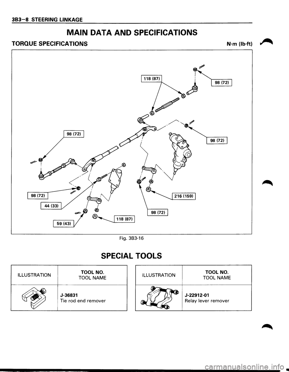
383-8 STEERING LINKAGE
MAIN DATA AND SPECIFICATIONS
TORQUE SPECIFICATIONS N·m (lb·ft)
Fig. 383-16
SPECIAL TOOLS
ILLUSTRATION TOOL NO.
TOOL NAME
TOOL NO.
TOOL NAME ILLUSTRATION
~
J-36831
Tie rod end remover
J-22912-01
Relay lever remover
..
Page 325 of 1928
HYDRAULIC BRAKES 5A-5
ON-VEHICLE SERVICE
FILLING MASTER CYLINDER
RESERVOIR
'\fl CAUTION:
'VI • Use only specified brake fluid. Do not use any
fluid which contains a petroleum base. Do not
use a container which has been used for
petroleum based fluids or a container which is
wet with water. Petroleum based fluids will
cause swelling and distortion of rubber parts in
the
hydraulic brake system. Water mixed with
brake fluid lowers the fluid boiling point. Keep
all fluid containers capped to prevent contami
nation.
• Always fill the master cylinder reservoir when
the engine is
cold.
•
Never allow the brake fluid to come in contact
with the painted surfaces.
The master
cylinder reservoir must be kept properly
filled
to ensure adequate reserve and to prevent air
and moisture
from entering the hydraulic system.
However, because
of expansion due to heat absorbed
from the brakes and the engine, the reservoir must not
be overfilled. The brake fluid reservoir is on the master
cylinder, which is located under the hood on the
left
side of the cowl. Thoroughly clean reservoir cap
before
removal to avoid getting dirt into reservoir.
Remove cap and diaphragm.
Add fluid as required to
bring level to the "MAX" mark on the reservoir tank.
Use
"DOT 3" Hydraulic Brake Fluid. If the fluid cap
diaphragm is stretched, return
it to the original position
before
installing.
DETERIORATION OF BRAKE FLUID
Using any other brake fluid than specified or brake fluid
with mineral oil or water mixed in will drop the boiling
point of brake fluid. It may, in turn, result in vapor lock
or deteriorated rubber parts of the hydraulic system.
Be sure to change brake fluid at specified intervals.
If rubber parts are deteriorated, remove all the system
parts and
clean them with alcohol. Prior to reassembly,
dry the cleaned parts with air to remove the alcohol.
Replace all
hoses and rubber parts of the system.
LEAKAGE OF BRAKE FLUID
With engine idling, set shift lever in the neutral position
and continue to depress brake
pedal at a constant
pressure.
Should the pedal stroke become deeper gradually,
leak from the hydraulic pressure system is possible.
Make sure
by visual check that there is no leak.
BLEEDING BRAKE HYDRAULIC SYSTEM
A bleeding operation is necessary to remove air from
the hydraulic brake system whenever air is introduced
into the hydraulic system.
It may be necessary to bleed
the hydraulic system at all four brakes if air has been
introduced through a
low fluid level or by dis
connecting brake pipes at the master cylinder. If a
brake pipe is disconnected at one
wheel, only that
wheel cylinder/caliper needs to be bled. If pipes are
disconnected at any fitting
located between master
cylinder and brakes, then the brake system served by
the disconnected pipe must
be bled.
1. For 4-wheel Antilock Brake System (ABS)
equipped
vehicle, be sure to remove the ABS
main fuse
40A located at the relay and fuse box
before
bleeding air. If you attempt to bleed air
without removing the main fuse, air cannot be let
out thoroughly, and this may cause damage to the
hydraulic unit.
After bleeding air, be sure to
replace the ABS main fuse back to its original
position.
2. Set the parking brake completely, then start the
engine.
NOTE:
The vacuum booster will be damaged if the
bleeding operation is performed with the engine
off.
3. Remove the master cylinder reservoir cap.
4. Fill the master cylinder reservoir with brake fluid.
Keep the reservoir at least half full during the air
bleeding operation.
5. Always use new brake fluid for replenishment.
6. In replenishing brake fluid, take care that air
bubbles do not enter the brake fluid.
•
When the master cylinder is replaced or
overhauled, first bleed the air from the master
cylinder, then from each
wheel cylinder and
caliper following the procedures described
below.
Bleeding the master cylinder (Fig. 5A-1}
7. Disconnect the rear wheel brake pipe
cylinder (Fig. 5A-1 ). Check the fluid level
and replenish as necessary. If replenished, leave
the system for at least one minute.
8. Depress the brake pedal slowly once and hold it
depressed.
9. Completely seal the delivery port of the master
cylinder where the pipe was disconnected with
your finger, then release the brake pedal slowly.
10. Release your finger from the delivery port when
the brake
pedal returns completely.
11. Repeat steps 7 through 9 until the brake fluid
comes out of the delivery port during step 7.