relay ISUZU TROOPER 1995 Service Manual
[x] Cancel search | Manufacturer: ISUZU, Model Year: 1995, Model line: TROOPER, Model: ISUZU TROOPER 1995Pages: 1928
Page 643 of 1928
ENGINE FUEL 6C-1
SECTION 6C
ENGINE FUEL
CONTENTS
General Description ....................... .
Fuel Metering ............................ .
On-Vehicle Service ........................ .
Fuel Filter ................................. .
In Tank Fuel Filter ............................. .
Fuel Pump Flow Test ........................ .
Fuel Pump Assembly ........................ .
Fuel Pump Relay .............................. ..
6C-1
6C-2
6C-3
6C-3
6C-4
6C-4
6C-5
6C-5
Fuel Tank .......................................... ..
Fuel Gage Unit ................................. ..
Fuel Filler Cap .................................... .
Accelerator Pedal Control ............... ..
Accelerator Pedal Control Cable ..
Accelerator Pedal ......................... .
Air
Cleaner Filter ........................... .
Main Data and Specifications ............... .
Torque Specifications ......................
..
6C-6
6C-7
6C-7
6C-8
6C-8
6C-9
6C-10
6C-11
6C-11
GENERAL DESCRIPTION
When working on the fuel system, there are several
things to keep in mind:
• Any time the fuel system is being worked on,
disconnect the negative battery
cable except for
those tests where battery voltage is required.
• Always keep a dry chemical (Class 8) fire extin
guisher near the work area.
• Replace all pipes with the same pipe and fittings
that were removed.
• Clean and inspect "0" rings. Replace if required.
• Always relieve the line pressure before servicing
any fuel system components.
• Do not attempt repairs on the fuel system until you
have read the instructions and checked the pic
tures
relating to that repair.
• Adhere to all Notices and Cautions.
All gasoline engines are designed to use only unleaded
gasoline. Unleaded gasoline
must be used for proper
emission control system operation. Its use will also
minimize spark plug fouling and extend engine oil life.
Using leaded gasoline can damage the emission
control system and could result in loss of emission
warranty coverage.
All cars are equipped with an Evaporative Emission
Control System. The purpose of the system is to
minimize the escape offuel vapors to the atmosphere.
Information on this system will be found in Section
6E2.
Page 646 of 1928
![ISUZU TROOPER 1995 Service Manual 6C - 4 ENGINE FUEL
I1!]1NSPECTION
After installation, start engine and check for fuel leak
age.
IN-TANK FUEL FILTER
The filter is located on the lower end of fuel pickup
tube in the fuel tank](/img/61/57183/w960_57183-645.png "ISUZU TROOPER 1995 Service Manual 6C - 4 ENGINE FUEL
I1!]1NSPECTION
After installation, start engine and check for fuel leak
age.
IN-TANK FUEL FILTER
The filter is located on the lower end of fuel pickup
tube in the fuel tank")
6C - 4 ENGINE FUEL
I1!]1NSPECTION
After installation, start engine and check for fuel leak
age.
IN-TANK FUEL FILTER
The filter is located on the lower end of fuel pickup
tube in the fuel tank. It prevents dirt from entering the
fuel pipe and also stops water unless the filter is
completely submerged in the water. It is a self-cleaning
type, not requiring scheduled maintenance. Excess
water and sediment in the tank restricts fuel supply to
the engine, resulting in engine stop. In such a case, the
tank
must be cleaned throughly.
FUEL PUMP FLOW TEST
If reduction of fuel supply is suspected, perform
checking as follows.
Preparation:
• Make sure that there is fuel in the tank.
• With the engine running, check the fuel feed
pipe and hose
from fuel tank to injector for
evidence of leakage.
Retighten, if pipe or hose connection is loose.
Also,
check pipes and hoses for squashing or
clogging.
1. Receive the hose from fuel feed pipe with a clean
container, and check for fuel pump flow rate.
2. Connect the pump relay terminals with a jumper
wire as shown and start the fuel pump to measure
delivery. (Fig. 6C-4)
W CAUTION:
Never generate sparks when connecting a jumper
wire.
Fig. 6C-4
Delivery Delivery
15 seconds 0.38
liters minimum
If the measure value is out of standard, conduct the
pressure test.
Pressure test
For the pressure test to the fuel system, see Section 6E
"Fuel Control System".
II
Page 647 of 1928
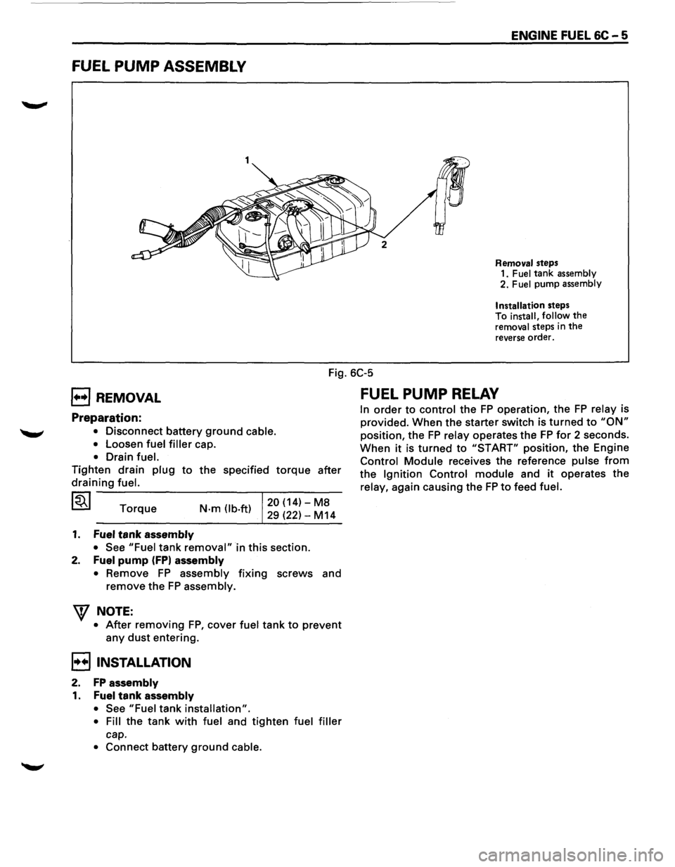
FUEL PUMP ASSEMBLY
1
ENGINE FUEL 6C-5
Removal steps
1. Fuel tank assembly 2. Fuel pump assembly
Installation
steps
To install, follow the removal steps in the reverse order.
Fig. 6C-5
B REMOVAL
Preparation:
• Disconnect battery ground cable.
•
Loosen fuel filler cap.
• Drain fuel.
Tighten drain plug to the specified torque after
draining fuel.
~ Torque N·m (lb.ft) 20 (14)-M8
29 (22)-M14
1. Fuel tank assembly
•
See "Fuel tank removal" in this section.
2. Fuel pump (FPI assembly
• Remove FP assembly fixing screws and
remove the FP assembly.
"'\f NOTE:
• After removing FP, cover fuel tank to prevent
any dust entering.
B INSTALLATION
2. FP assembly
1. Fuel tank assembly
• See "Fuel tank installation".
• Fill the tank with fuel and tighten fuel filler
cap.
• Connect battery ground cable.
FUEL PUMP RELAY
In order to control the FP operation, the FP relay is
provided. When the starter switch is turned to "ON"
position, the FP relay operates the FP for 2 seconds.
When it is turned to "START" position, the Engine
Control Module receives the reference pulse from
the Ignition Control module and it operates the
relay, again causing the FP to feed fuel.
Page 659 of 1928
CRANKING SYSTEM 6D2 - 1
SECTION 602
CRANKING SYSTEM
CONTENTS
General Description ....................... .
Diagnosis
.................................... .
On-Vehicle Service ........................ . 6D2-1
6D2-3
6D2-8 Unit
Repair.................................... 6D2-9
Main Data and Specifications
............ 6D2-17
Torque Specifications
...................... 6D2-18
GENERAL DESCRIPTION
CRANKING CIRCUIT
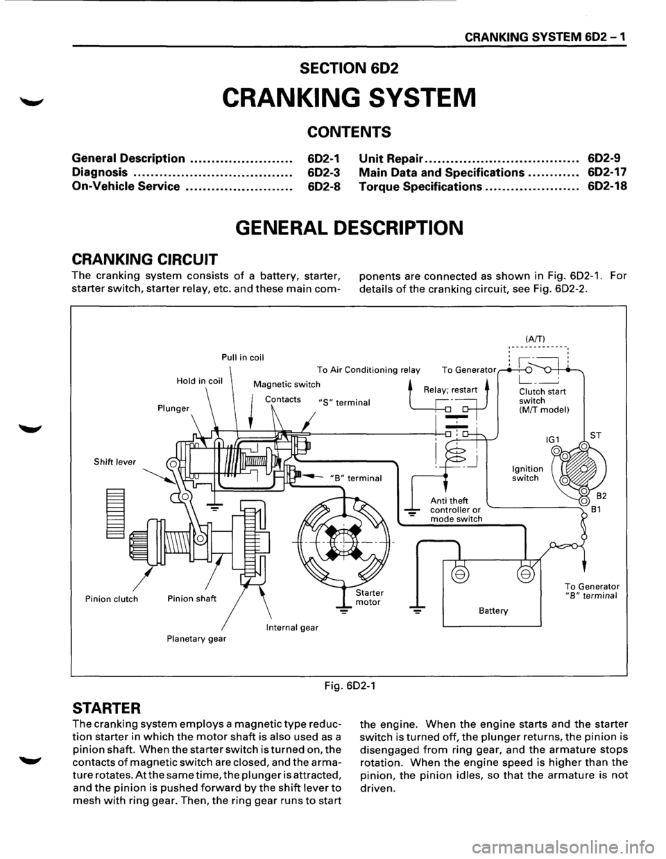
The cranking system consists of a battery, starter,
starter switch, starter relay, etc. and these main com-
Pull in coil
Hold
in coil
Plunger
Shift lever
Pinion clutch
Internal
gear
Planetary gear
ponents are connected as shown in Fig. 602-1. For
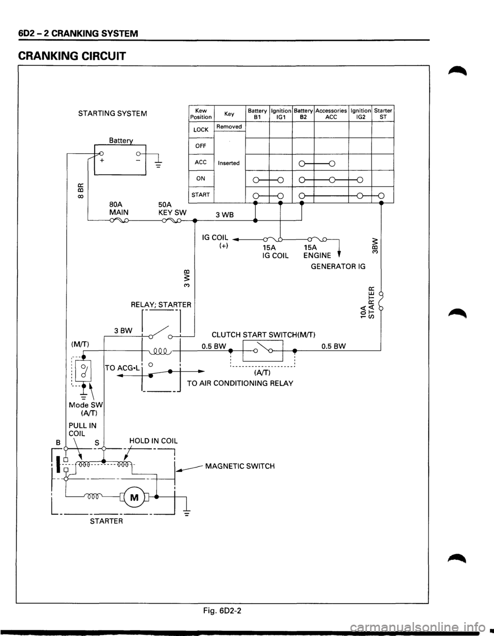
details of the cranking circuit, see Fig. 602-2.
Anti theft controller or mode switch
Battery
(AfT} '-------------. ' '
To Generator "B" terminal
Fig. 602-1
STARTER
The cranking system employs a magnetic type reduc
tion starter in which the motor shaft is also used as a
pinion shaft. When the starter switch is turned on, the
contacts of magnetic switch are closed, and the arma
ture rotates. At the same time, the plunger is attracted,
and the pinion is pushed forward by the shift lever to
mesh with ring gear. Then, the ring gear runs to start
the engine. When the engine starts and the starter
switch is turned off, the plunger returns, the pinion is
disengaged from ring gear, and the armature stops
rotation. When the engine speed is higher than the
pinion, the pinion idles, so that the armature is not
driven.
Page 660 of 1928
602 - 2 CRANKING SYSTEM
CRANKING CIRCUIT
STARTING SYSTEM
a: co 00
/ +
Battery
50 A
Kew
Position
LOCK
OFF
Key
Removed
ACC Inserted
ON
START Battery
Ignition Battery
Accessories Ignition Starter B1 IG1 B2 ACC IG2 ST
o----o
o----o
oc l---+----+--<0---o
BOA MAIN KEYSW 3WB I I ~~ ...;~-4:) -
IG COIL --------1~-:r uJ----a~ (+) 15A 15A IG COIL ENGINE
GENERATOR IG co :5: ('f)
RELAY; STARTER
3BW r---~
._,()-.L___j -v CLUTCH START SWITCH(M/T)
0.5
BW-I '~ I -0.5 BW ~-+-4~--~~~------~ T I ~ I T : ___________________ ~
.. (NT)
TO AIR CONDITIONING RELAY
Mode SW (NT)
PULLIN
B C\~L _S -/OLD I~ COl~
fl-~ooe--------O<>Ol -----MAGNETIC SWITCH
~-T ------+-----~.
I M
L _______ _
STARTER
Fig. 602-2
•
Page 662 of 1928
602 - 4 CRANKING SYSTEM
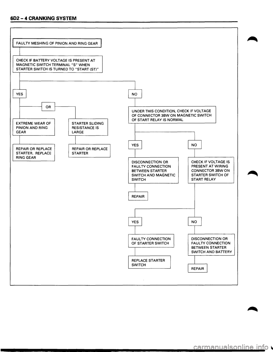
FAULTY MESHING OF PINION AND RING GEAR I
CHECK IF BATTERY VOLTAGE IS PRESENT AT MAGNETIC SWITCH TERMINAL "S" WHEN STARTER SWITCH IS TURNED TO "START (ST)"
YES
I NO I
I OR I I
I
UNDER THIS CONDITION, CHECK IF VOLTAGE OF CONNECTOR 3BW ON MAGNETIC SWITCH
OF START RELAY IS NORMAL EXTREME WEAR OF STARTER SLIDING
PINION AND RING RESISTANCE IS GEAR LARGE
I
I YES I NO I REPAIR OR REPLACE REPAIR OR REPLACE STARTER. REPLACE STARTER
RING GEAR
DISCONNECTION OR CHECK IF VOLTAGE IS
FAULTY CONNECTION PRESENT AT WIRING
BETWEEN STARTER
CONNECTOR 3BW ON
SWITCH
AND MAGNETIC STARTER
SWITCH OF
SWITCH START RELAY
REPAIR I
YES I NO I
FAULTY CONNECTION
DISCONNECTION OR
OF STARTER
SWITCH FAULTY CONNECTION BETWEEN STARTER
SWITCH AND BATTERY
REPLACE
STARTER
I SWITCH REPAIR l
Page 663 of 1928
CRANKING SYSTEM 602-5
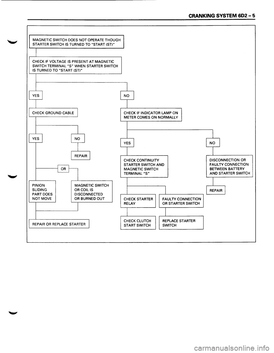
MAGNETIC SWITCH DOES NOT OPERATE THOUGH STARTER SWITCH IS TURNED TO "START (ST)"
CHECK IF VOLTAGE IS PRESENT AT MAGNETIC
SWITCH TERMINAL "S" WHEN STARTER SWITCH
IS TURNED TO "START (ST)"
YES
I NO I
CHECK GROUND CABLE I CHECK IF INDICATOR LAMP ON METER COMES ON NORMALLY
I
I
YES I NO I YES I I I
NO
I REPAIR I CHECK CONTINUITY DISCONNECTION OR
STARTER SWITCH AND FAULTY CONNECTION
OR MAGNETIC
SWITCH BETWEEN BATTERY
TERMINAL "S" AND STARTER SWITCH
I PINION
MAGNETIC SWITCH
SLIDING
OR COIL IS I REPAIR I PART DOES DISCONNECTED NOT MOVE OR BURNED OUT CHECK STARTER FAULTY CONNECTION
I
RELAY OR STARTER SWITCH
I
REPAIR OR REPLACE STARTER I CHECK CLUTCH REPLACE STARTER
START SWITCH SWITCH
Page 678 of 1928
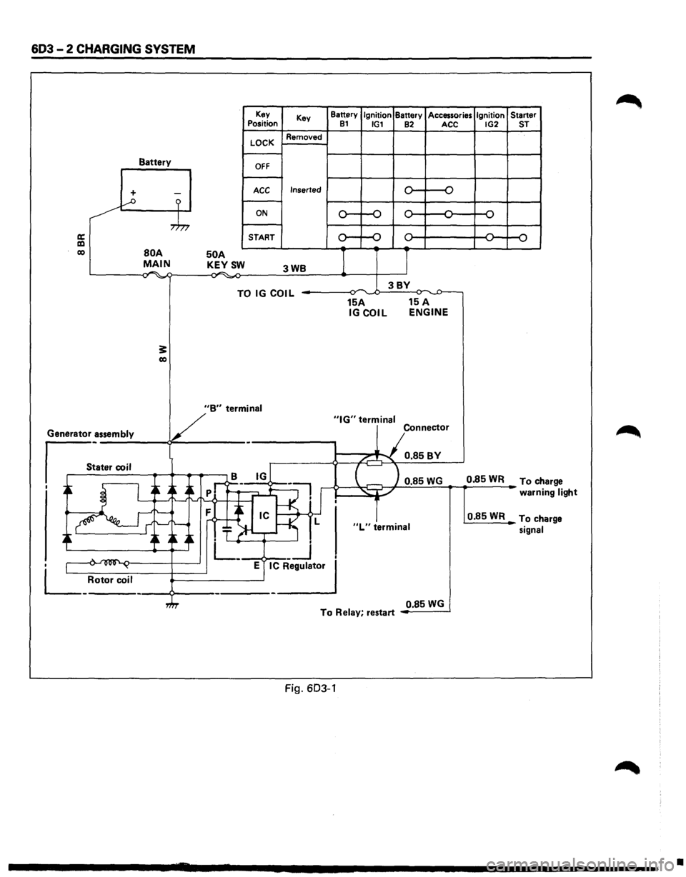
603-2 CHARGING SYSTEM
Battery
+ -...--o ?
,.h,
a: a:l co BOA MAIN . .-. -,., ~
3: co
50 A KEYSW
Key
Position
LOCK
OFF
ACC
ON
START Key
Removed
Inserted
3WB
TO IG COIL
Battery Ignition Battery Accessories Ignition Starter 81 IG1 82 ACC IG2 ST
0 -o
,.... ,....
,.... ,... ,.... ...., ...., ...., ...., ....,
0 ,.... ,.... ,.... 0 ....,
...., ....,
I J
3BY ~ ,.,.
15A 15 A IGCOIL ENGINE
V
"B" termin_a_I _____ _,"IG" terminal
Generator assembly
s_:a_t_er_co __ i_l __ ~~~.-.-~ - Connector
/...-"""\. 0.85BY
B IG
I ~ I ~ A~
-~ ..->--~~ 0.85 WG 0.85 WR To ch arge
' _-: .~:f--<·1'
.~ ~ ~~~~ T ~-r-~ L
. L_ __j
• 1 .... ~ ~ E IC Regulator
L_ Rotor coil ----9---------------'
"L" terminal
warni ng light
0.85WR To ch arge
signal
0.85
WG To Relay, restart
Fig. 603-1
•
Page 701 of 1928
......, .., LU
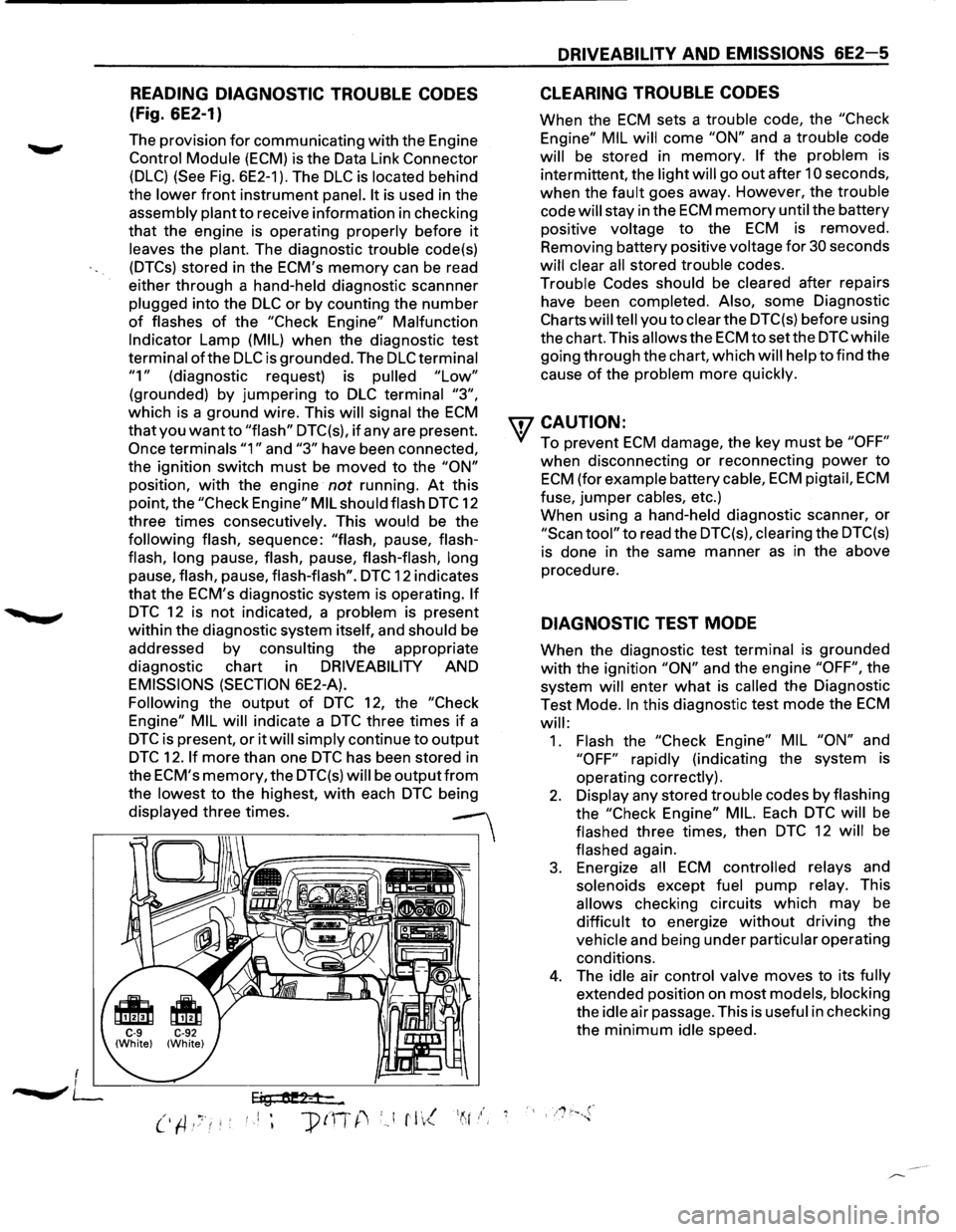
READING DIAGNOSTIC TROUBLE CODES
(Fig. 6E2-1)
The provision for communicating with the Engine
Control Module (ECM) is the Data Link Connector
(DLC) (See Fig. 6E2-1 ). The DLC is located behind
the
lower front instrument panel. It is used in the
assembly plant
to receive information in checking
that the engine is operating properly before it
leaves the plant. The diagnostic trouble code(s)
(DTCs) stored in the ECM's memory can be read
either through a hand-held diagnostic scannner
plugged into the
DLC or by counting the number
of flashes of the "Check Engine" Malfunction
Indicator Lamp (MIL) when the diagnostic test
terminal
ofthe DLC is grounded. The DLC terminal
"1" (diagnostic request) is pulled "Low"
(grounded) by jumpering to DLC terminal "3",
which is a ground wire. This will signal the ECM
that you want to "flash" DTC(s), if any are present.
Once terminals "1" and "3" have been connected,
the ignition switch
must be moved to the "ON"
position, with the engine not running. At this
point, the
"Check Engine" MIL should flash DTC 12
three times consecutively. This
would be the
following flash, sequence: "flash, pause, flash
flash,
long pause, flash, pause, flash-flash, long
pause, flash, pause, flash-flash". DTC 12 indicates
that the ECM's diagnostic system is operating.
If
DTC 12 is not indicated, a problem is present
within the diagnostic system itself, and should be
addressed
by consulting the appropriate
diagnostic chart in
DRIVEABILITY AND
EMISSIONS (SECTION 6E2-A).
Following the output of DTC 12, the "Check
Engine" MIL
will indicate a DTC three times if a
DTC is present, or it will simply continue to output
DTC 12. If more than one DTC has been stored in
the
ECM's memory, the DTC(s) will be outputfrom
the lowest to the highest, with each DTC being
displayed three times.
--
Eig tU!2-1-...
DRIVEABILITY AND EMISSIONS 6E2-5
CLEARING TROUBLE CODES
When the ECM sets a trouble code, the "Check
Engine" MIL
will come "ON" and a trouble code
will be stored in memory. If the problem is
intermittent, the light
will go out after 10 seconds,
when the fault goes away. However, the trouble
code
will stay in the ECM memory until the battery
positive voltage
to the ECM is removed.
Removing battery positive voltage
for 30 seconds
will clear all stored trouble codes.
Trouble
Codes should be cleared after repairs
have been completed. Also, some Diagnostic
Charts will tell you to clear the DTC(s) before using
the chart. This
allows the ECM tosetthe DTCwhile
going through the chart, which will help to find the
cause
of the problem more quickly.
wcAUTION:
• To prevent ECM damage, the key must be "OFF"
when disconnecting or reconnecting power to
ECM (for example battery cable, ECM pigtail, ECM
fuse, jumper cables, etc.)
When using a hand-held diagnostic scanner,
or
"Scan tool" to read the DTC(s), clearing the DTC(s)
is done in the same manner as in the above
procedure.
DIAGNOSTIC TEST MODE
When the diagnostic test terminal is grounded
with the ignition "ON" and the engine "OFF", the
system
will enter what is called the Diagnostic
Test Mode.
In this diagnostic test mode the ECM
will:
1. Flash the "Check Engine" MIL "ON" and
"OFF" rapidly (indicating the system is
operating correctly).
2. Display any stored trouble codes by flashing
the
"Check Engine" MIL. Each DTC will be
flashed three times, then
DTC 12 will be
flashed again.
3. Energize all ECM controlled relays and
solenoids except
fuel pump relay. This
allows checking circuits which may be
difficult to energize without driving the
vehicle and being under particular operating
conditions.
4. The idle air control valve moves to its fully
extended position on most models, blocking
the
idle air passage. This is useful in checking
the
minimum idle speed.
Page 702 of 1928
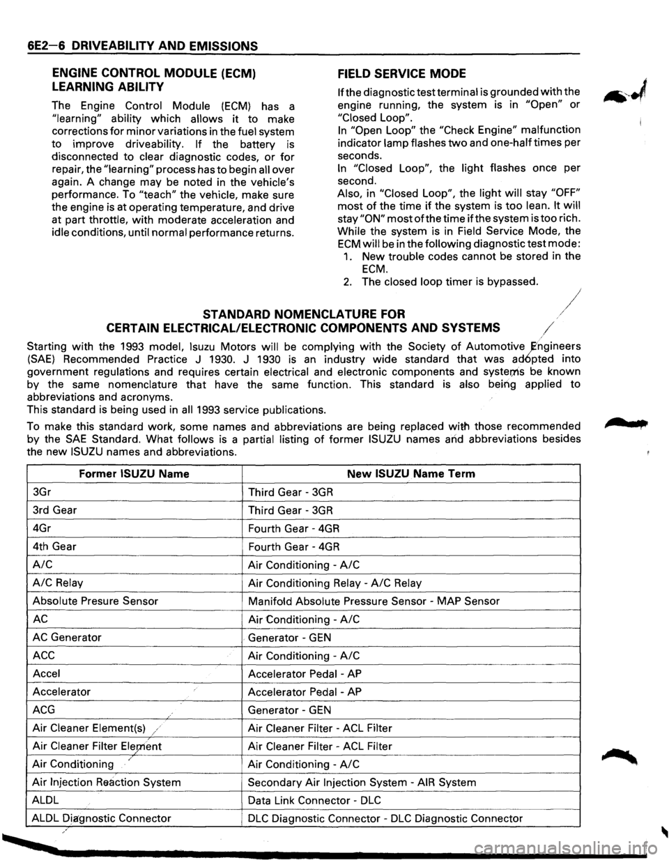
6E2-6 DRIVEABILITY AND EMISSIONS
FIELD SERVICE MODE
ENGINE
CONTROL MODULE (ECM)
LEARNING ABILITY
The Engine Control Module (ECM) has a
"learning"
ability which allows it to make
corrections
for minor variations in the fuel system
to improve driveability. If the battery is
disconnected to clear diagnostic codes, or for
repair, the "learning" process has to begin all over
again. A change
may be noted in the vehicle's
performance. To "teach" the vehicle, make sure
the engine is at operating temperature, and drive
at part throttle, with moderate acceleration and
idle conditions, until normal performance returns.
lfthe diagnostic test terminal is grounded with the
engine running, the system is in
"Open" or
"Closed Loop".
In "Open Loop" the "Check Engine" malfunction
indicator lamp flashes
two and one-halftimes per
seconds.
In "Closed Loop", the light flashes once per
second.
Also, in "Closed
Loop", the light will stay "OFF"
most of the time if the system is too lean. It will
stay"ON" mostofthetime if the system is too rich.
While the system is in Field Service Mode, the
ECM will be in the following diagnostic test mode:
1. New trouble codes cannot be stored in the
ECM.
2. The closed loop timer is bypassed.
STANDARD NOMENCLATURE FOR /
CERTAIN ELECTRICAL/ELECTRONIC COMPONENTS AND SYSTEMS /
Starting with the 1993 model, lsuzu Motors will be complying with the Society of Automotive ~ngineers
(SAE) Recommended Practice J 1930. J 1930 is an industry wide standard that was ad6pted into
government regulations and requires certain electrical and electronic components and
syster;ns be known
by the same
nomenclature that have the same function. This standard is also being applied to
abbreviations and acronyms.
This standard is being used in
all 1993 service publications.
To make this standard work, some names and abbreviations are being replaced
with those recommended
by the
SAE Standard. What follows is a partial listing of former ISUZU names and abbreviations besides
the
new ISUZU names and abbreviations.
Former ISUZU Name New ISUZU Name Term
3Gr
Third Gear -3GR
3rd Gear
Third Gear -3GR
4Gr
Fourth Gear -4GR
4th Gear
Fourth Gear -4GR
A/C Air Conditioning -A/C
A/C
Relay Air Conditioning Relay -A/C Relay
Absolute Presure Sensor
Manifofd Absolute Pressure Sensor -MAP Sensor
AC Air Conditioning -A/C
AC Generator . Generator -GEN
ACC Air Conditioning -A/C
Accel
Accelerator Pedal -AP
Accelerator
Accelerator Pedal -AP
ACG Generator -GEN
Air Cleaner Element(s) / Air Cleaner Filter -ACL Filter
Air Cleaner Filter Ele;nent Air Cleaner Filter -ACL Filter
Air Conditioning / Air Conditioning -A/C
Air Injection Reaction System Secondary Air Injection System -AIR System
ALDL Data Link Connector -
DLC
ALDL Diagnostic Connector DLC Diagnostic Connector -DLC Diagnostic Connector ,.
, ....