relay ISUZU TROOPER 1995 Repair Manual
[x] Cancel search | Manufacturer: ISUZU, Model Year: 1995, Model line: TROOPER, Model: ISUZU TROOPER 1995Pages: 1928
Page 705 of 1928
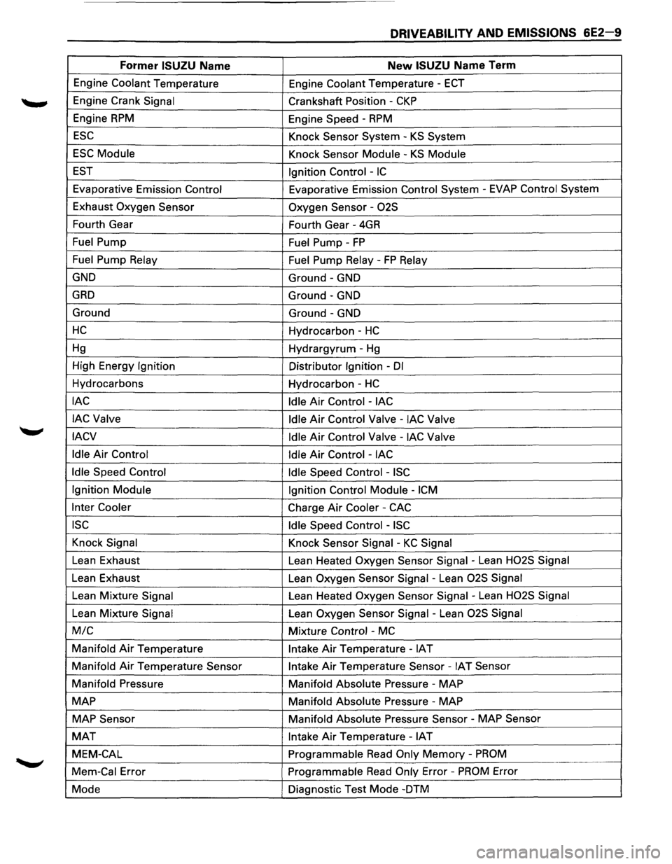
DRIVEABILITY AND EMISSIONS 6E2-9
Former ISUZU Name New ISUZU Name Term
Engine Coolant Temperature
Engine Coolant Temperature -ECT
Engine Crank Signal Crankshaft Position -CKP
Engine RPM Engine Speed -RPM
ESC Knock Sensor System-KS System
ESC Module Knock Sensor Module -KS Module
EST Ignition Control -IC
Evaporative Emission Control Evaporative Emission Control System -EVAP Control System
Exhaust Oxygen Sensor
Oxygen Sensor -
02S
Fourth Gear
Fourth Gear -4GR
Fuel Pump Fuel Pump -FP
Fuel Pump Relay
Fuel Pump Relay -FP Relay
GND Ground-GND
GAD Ground-GND
Ground Ground-GND
HC Hydrocarbon -HC
Hg Hydrargyrum-Hg
High Energy Ignition Distributor Ignition -Dl
Hydrocarbons
Hydrocarbon -HC
lAC
Idle Air Control-lAC
lAC Valve
Idle
Air Control Valve-lAC Valve
IACV Idle
Air Control Valve -lAC Valve
Idle
Air Control Idle Air Control -lAC
Idle
Speed Control Idle Speed Control -ISC
Ignition Module
Ignition Control Module -ICM
Inter Cooler Charge Air Cooler -CAC
ISC Idle Speed Control -ISC
Knock Signal Knock Sensor Signal -KC Signal
Lean Exhaust
Lean Heated Oxygen Sensor Signal -Lean H02S Signal
Lean Exhaust
Lean Oxygen Sensor Signal -Lean 02S Signal
Lean Mixture Signal Lean Heated Oxygen Sensor Signal -Lean H02S Signal
Lean Mixture Signal Lean Oxygen Sensor Signal -Lean 02S Signal
M/C Mixture Control -MC
Manifold Air Temperature Intake Air Temperature-IAT
Manifold
Air Temperature Sensor Intake Air Temperature Sensor-IAT Sensor
Manifold Pressure Manifold Absolute Pressure -MAP
MAP
Manifold Absolute Pressure -MAP
MAP Sensor
Manifold Absolute Pressure Sensor -MAP Sensor
MAT Intake Air Temperature-IAT
MEM-CAL Programmable Read Only Memory -PROM
Mem-Cal Error Programmable Read Only Error -PROM Error
Mode Diagnostic
Test Mode -DTM
Page 708 of 1928
6E2-12 DRIVEABILITY AND EMISSIONS
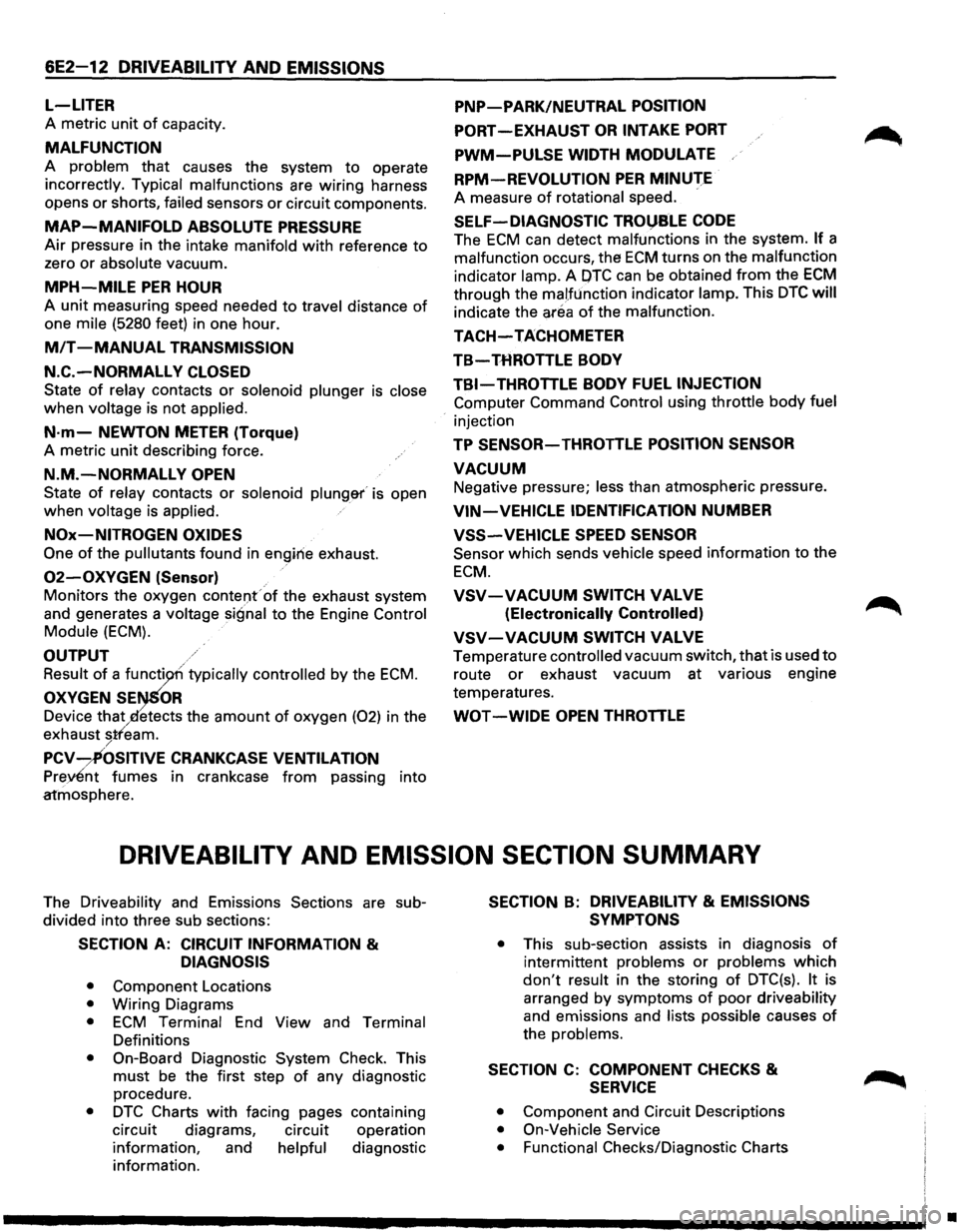
L-LITER
A metric unit of capacity.
MALFUNCTION
A problem that causes the system to operate
incorrectly. Typical malfunctions are wiring harness
opens
or shorts, failed sensors or circuit components.
MAP-MANIFOLD ABSOLUTE PRESSURE
Air pressure in the intake manifold with reference to
zero or absolute vacuum.
MPH-MILE PER HOUR
A unit measuring speed needed to travel distance of
one mile (5280 feet) in one hour.
MIT -MANUAL TRANSMISSION
N.C.-NORMALLY CLOSED
State of relay contacts or solenoid plunger is close
when voltage is not applied.
N·m-NEWTON METER (Torque)
A metric unit describing force.
N.M.-NORMALLY OPEN
State of relay contacts or solenoid plung&r' is open
when voltage is applied.
NOx-NITROGEN OXIDES
One of the pullutants found in engirie exhaust.
02-0XYGEN (Sensor)
Monitors the oxygen contel)f of the exhaust system
and generates a
voltage signal to the Engine Control
Module (ECM).
OUTPUT
Result of a functi typically controlled by the ECM.
OXYGEN SE OR
Device that etects the amount of oxygen (02) in the
exhaust
stfeam. /
PCV-~OSITIVE CRANKCASE VENTILATION
Prey£nt fumes in crankcase from passing into
atmosphere.
PNP-PARK/NEUTRAL POSITION
PORT-EXHAUST OR INTAKE PORT
PWM-PULSE WIDTH MODULATE
RPM-REVOLUTION PER MINUTE
A measure of rotational speed.
SELF-DIAGNOSTIC TROl)SLE CODE
The ECM can detect malfunctions in the system. If a
malfunction occurs, the ECM turns on the malfunction
indicator lamp. A OTC can be obtained from the ECM
through the malfunction indicator lamp. This DTC will
indicate the area of the malfunction.
TACH-TACHOMETER
TB-THROTTLE BODY
TBI-THROTTLE BODY FUEL INJECTION
Computer Command Control using throttle body fuel
injection
TP SENSOR-THROTTLE POSITION SENSOR
VACUUM
Negative pressure; less than atmospheric pressure.
VIN-VEHICLE IDENTIFICATION NUMBER
VSS-VEHICLE SPEED SENSOR
Sensor which sends vehicle speed information to the
ECM.
VSV-VACUUM SWITCH VALVE
(Electronically Controlled)
VSV-VACUUM SWITCH VALVE
Temperature controlled vacuum switch, that is used to
route or exhaust vacuum at various engine
temperatures.
WOT -WIDE OPEN THROTTLE
DRIVEABILITV AND EMISSION SECTION SUMMARY
The Driveability and Emissions Sections are sub
divided into three sub sections:
SECTION A: CIRCUIT INFORMATION &
DIAGNOSIS
• Component Locations
• Wiring Diagrams
• ECM Terminal End View and Terminal
Definitions
• On-Board Diagnostic System Check. This
must be the first step of any diagnostic
procedure.
• DTC Charts with facing pages containing
circuit diagrams, circuit operation
information, and
helpful diagnostic
information.
SECTION B: DRIVEABILITY & EMISSIONS
SYMPTONS
• This sub-section assists in diagnosis of
intermittent problems or problems which
don't result in the storing of DTC(s). It is
arranged
by symptoms of poor driveability
and emissions and lists possible causes of
the problems.
SECTION C: COMPONENT CHECKS &
SERVICE
• Component and Circuit Descriptions
• On-Vehicle Service
• Functional
Checks/Diagnostic Charts
•
Page 716 of 1928
6E2-20 DRIVEABILITV AND EMISSIONS
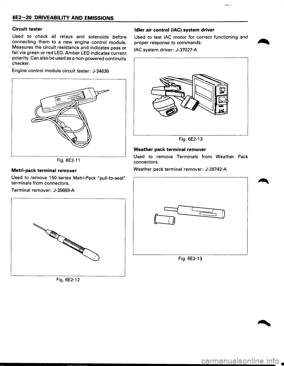
Circuit tester
Used to check all relays and solenoids before
connecting them to a
new engine control module.
Measures the circuit resistance and indicates pass or
fail via green or red LED. Amber LED indicates current
polarity. Can also be used as a non-powered continuity
checker.
Engine
control module circuit tester: J-34636
Fig.
6E2-11
Metri-pack terminal remover
Used to remove 150 series Metri-Pack "pull-to-seat"
terminals
from connectors.
Terminal remover: J-35689-A
Fig. 6E2-12
Idler air control (lAC) system driver
Used to test lAC motor for correct functioning and
proper response to commands.
lAC system driver: J-37027-A
Fig. 6E2-13
Weather pack terminal remover
Used to remove Terminals from Weather Pack
connectors.
Weather pack terminal remover: J-28742-A
Fig. 6E2-13
•
Page 719 of 1928
DRIVEABILITY AND EMISSIONS 6E2-23
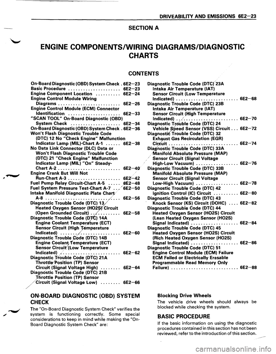
SECTION A
ENGINE COMPONENTS/WIRING DIAGRAMS/DIAGNOSTIC
CHARTS
CONTENTS
On-Board Diagnostic (OBD} System Check . 6E2-23
Basic Procedure . . . . . . . . . . . . . . . . . . . . . 6E2-23
Engine Component Location . . . . . . . . . . 6E2-24
Engine Control Module Wiring
Diagrams . . . . . . . . . . . . . . . . . . . . . . . . . 6E2-26
Engine Control Module (ECM) Connector
Identification . . . . . . . . . . . . . . . . . . . . . 6E2-33
"SCAN TOOL" On-Board Diagnostic (OBD)
System Check . . . . . . . . . . . . . . . . . . . . 6E2-34
On-Board Diagnostic (OBD} System Check . 6E2-36
Won't Flash Diagnostic Trouble Code
(DTC)
12 No "Check Engine" Malfunction
Indicator Lamp (MIL)-Chart A-1 . . . . . . 6E2-38
No Data Link Connector (DLC) Data or
Won't Flash Diagnostic Trouble Code
(DTC)
21 "Check Engine" Malfunction
Indicator Lamp (MIL} "On" Steady-
Chart A-2 . . . . . . . . . . . . . . . . . . . . . . . . . 6E2-40
Engine Crank But Will Not
Run-Chart A-3 . . . . . . . . . . . . . . . . . . . . . 6E2:.....42
Fuel Pump Relay Circuit-Chart A-5 . . . . . 6E2-48
Fuel System Pressure Test-Chart A-7 ..• /6E2-50
Intake Manifold Diagnostic Plate Chart/
A-8 ......................... ,-:· . . . 6E2-56
Diagnostic Trouble Code (DTC~13 /
Heated Oxygen Sensor (H02 Circuit
(Open Grounded Circuit) . . . . . . . . . . . 6E2-58
Diagnostic Trouble Code (D'JiC) 14A
Engine Coolant Temperaiure (ECT}
Sensor Circuit (High -:remperature
Indicated) ....... /. . . . . . . . . . . . . . . . 6E2-60
Diagnostic Trouble P'ode (DTC} 14B
Engine
Coolan·vremperature (ECT)
Sensor Circuit'(Low Temperature
Indicated) ./. . . . . . . . . . . . . . . . . . . . . . . 6E2-62
Diagnostic Jtouble Code (DTC) 21A
Throtti~,.Position (TP) Sensor
Circu)t (Signal Voltage High) . . . . . . . . 6E2-64
Diag.,Ostic Trouble Code (DTC) 21B
Jflrottle Position (TP} Sensor
//Circuit (Signal Voltage Low} ........ 6E2-66
ON-BOARD DIAGNOSTIC (OBD) SYSTEM
CHECK
The "On-Board Diagnostic System Check" verifies the
system is functioning correctly.
Some special
considerations
to keep in mind while making the "On
Board Diagnostic System Check" are:
Diagnostic Trouble Code (DTC(23A
Intake Air Temperature (IAT)
Sensor Circuit (low Temperature
Indicated) ......................... 6E2-68
Diagnostic Trouble Code (DTC) 23B
Intake Air Temperature (IAT)
Sensor Circuit (High Temperature
Indicated) ... / ...................... 6E2-70
Diagnostic T[ouble Code (DTC} 24
Vehicle )!Peed Sensor (VSS} Circuit ... 6E2-72
DiagnostiC Trouble Code (DTC) 32
Exh,tist Gas Recirculation (EGR}
Cir,.Cuit ............................ 6E2-74
Dia,gnostic Trouble Code (DTC} 33A
·Manifold Absolute Pressure (MAP)
Sensor Circuit (Signal Voltage
High-Low Vacuum) ................. 6E2-76
Diagnostic Trouble Code (DTC) 33B
Manifold Absolute Pressure (MAP}
Sensor Circuit (Signal Voltage
Low-High Vacuum) ................. 6E2-78
Diagnostic Trouble Code (DTC) 42
Ignition Control (IC) Circuit . . . . . . . . . . 6E2-80
Diagnostic Trouble Code (DTC} 43
Knock Sensor (KS} Circuit (DOHC) .... 6E2-82
Diagnostic Trouble Code (DTC) 44
Heated Oxygen Sensor (H02S} Circuit
(Lean Heated Oxygen Sensor (H02S)
Signal Indicated} . . . . . . . . . . . . . . . . . . . 6E2-84
Diagnostic Trouble Code (DTC) 45
Heated Oxygen Sensor (H02S) Circuit
(Rich Heated Oxygen Sensor (H02S)
Signal Indicated) . . . . . . . . . . . . . . . . . . . 6E2-86
Diagnostic Trouble Code (DTC) 51
Engine Control Module (ECM} Failure
ECM Failed
or Electrically Erasable
Programmable Read Memory Only
Failure} ........................... 6E2-88
Blocking Drive Wheels
The vehicle drive wheels should always be
blocked
while checking the system.
BASIC PROCEDURE
If the basic information on using the diagnostic
procedures contained in this section has
not been
reviewed, refer
to the introduction of this section.
Page 720 of 1928
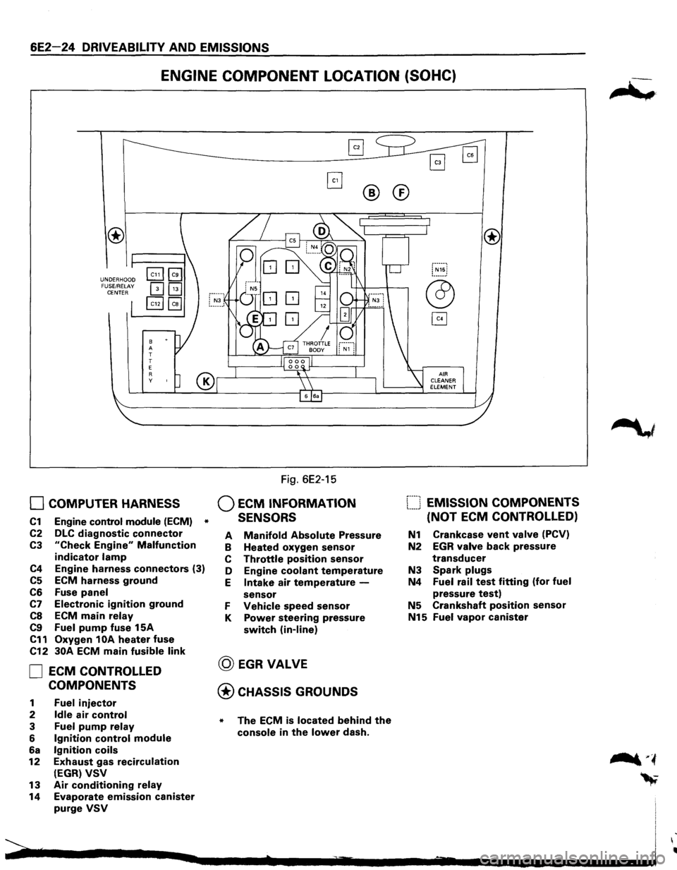
6E2-24 DRIVEABILITY AND EMISSIONS
ENGINE COMPONENT LOCATION (SOHC)
UNDERHOOD
FUSE/RELAY
CENTER
8 A
T
T
E
R y
0 COMPUTER HARNESS
C1 Engine control module (ECM) *
C2 DLC diagnostic connector
C3 "Check Engine" Malfunction
indicator lamp
C4 Engine harness connectors (3)
C5 ECM harness ground
C6 Fuse panel
C7 Electronic ignition ground
CS ECM main relay
C9 Fuel pump fuse 15A
C11 Oxygen 1 OA heater fuse
C12 30A ECM main fusible link
0 ECM CONTROLLED
COMPONENTS
1 Fuel injector
2 Idle air control
3 Fuel pump relay
6 Ignition control module
6a Ignition coils
12 Exhaust gas recirculation
(EGR) VSV
13 Air conditioning relay
14 Evaporate emission canister
purge VSV
Fig. 6E2-15
Q ECM INFORMATION
SENSORS
®
A Manifold Absolute Pressure
B Heated oxygen sensor
C Throttle position sensor
D Engine
coolant temperature
E Intake air temperature -
sensor
F Vehicle speed sensor
K Power steering pressure
switch (in-line)
@ EGRVALVE
@CHASSIS GROUNDS
* The ECM is located behind the
console in the lower dash.
®
[::::J EMISSION COMPONENTS
(NOT
ECM CONTROLLED)
N1 Crankcase vent valve (PCV)
N2 EGR valve back pressure
transducer
N3 Spark plugs
N4 Fuel rail test fitting (for fuel
pressure test)
N5 Crankshaft position sensor
N15 Fuel vapor canister
Page 721 of 1928
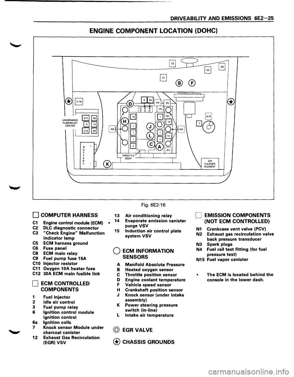
DRIVEABILITY AND EMISSIONS 6E2-25
ENGINE COMPONENT LOCATION (DOHC)
®B
UNDERHOOD FUSE/RELAY CENTER
B A T
T
E
A y
0 COMPUTER HARNESS
C1 Engine control module (ECM)
C2 DLC diagnostic connector
C3 "Check Engine" Malfunction
indicator lamp
C5 ECM harness ground
C6 Fuse panel
C8 ECM main relay
C9 Fuel pump fuse 15A
C10 Injector resistor
C11 Oxygen 1 OA heater fuse
C12
30A ECM main fusible link
0 ECM CONTROLLED
COMPONENTS
1 Fuel injector
2 Idle air control
3 Fuel pump relay
6 Ignition control module
ignition control
6a Ignition coils
7 Knock sensor Module under
charcoal canister
12
Exhaust Gas Recirculation
(EGR) VSV
*
®®
Fig. 6E2-16
13 Air conditioning relay
14 Evaporate emission canister
purge VSV
15 Induction air control plate
system VSV
Q ECM INFORMATION
SENSORS
A Manifold Absolute Pressure
B Heated oxygen sensor
c Throttle position sensor
D Engine
coolant temperature
F Vehicle speed sensor
H Crankshaft
position sensor
J Knock sensor
(under intake
assembly)
K Power steering pressure
switch (in-line)
L Intake air temperature
@ EGRVALVE
@ CHASSIS GROUNDS
f----1 EMISSION COMPONENTS !.-----' (NOT ECM CONTROLLED)
N1 Crankcase vent valve (PCV)
N2 Exhaust gas
recirculation valve
back pressure transducer
N3 Spark plugs
N4 Fuel rail test fitting (for fuel
pressure test)
N15 Fuel vapor canister
* The ECM is located behind the
console in the lower dash.
Page 723 of 1928
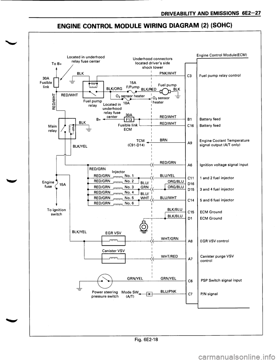
DRIVEABILITY AND EMISSIONS 6E2-27
ENGINE CONTROL MODULE WIRING DIAGRAM (2) (SOHC)
Located in underhood Engine Control
Module(ECM) Underhood connectors
To B+ relay fuse center located driver's side
/r BLK r----------s-ho-c-1-:-t-ow_:_::...:~.:..:K!Wc..:...:..:H:...:T.:..__---I C3 Fuel pump relay control
30A
Fusible
link
15A I F/P 1 Fuel pump BLK/ORG ~~
02 sensor heater 1 1 0 -2 sensor -10A 1 heater Fuel pump
BLK/YEL
relay Located in underhood relay fuse
center
B+ ------1
I
REO/WHT t---.-----t--:..:.::::..=.!...:...:..:..:...:_.:..._--1 B 1 Battery feed
REO/WHT
'-----t--..:.:..::-=:!....:c.:.:...:.-=-------1 C16 Battery feed
TCM BRN (C91-014) -_.:..._--=..:..:..:...:----1 A9 Engine Coolant Temperature signal output (A/T only)
L----~-----------~~-.:..:R.:::EO~/~G~R~N_:_--IA6 Ignition
voltage signal input
Engine
fuse 15A
To
ignition switch BLK/YEL
=
REO/GRN
REO/GRN
REO/GRN
REO/GRN
REO/GRN
REO/GRN
REO/GRN
ORG/BLU 016
ORG/BLU 015
L:...:..::..:-=---.....-:..:.:....:...!._{ L_B::..:L:..:U:c..IW:..:..:...:.HT_:__--l c " 14
BLK/BLU C15
,--.----<.._.:::B.:::LKI=B.::.LU=---1 01
GRN/YEL GRN/YEL
~--~~~~--~~~~--~C6
Power steering Mode SW--+*-f--=-8=-LU~/.:..P.:..:N~K:___---l pressure switch (A/T) C7
Fig. 6E2-18
1 and 2 fuel injector
3 and 4 fuel injector
5 and 6 fuel injector
ECM Ground
ECM Ground
EGR VSV control
Canister purge VSV
control
PSP Switch signal input
P/N signal
Page 724 of 1928
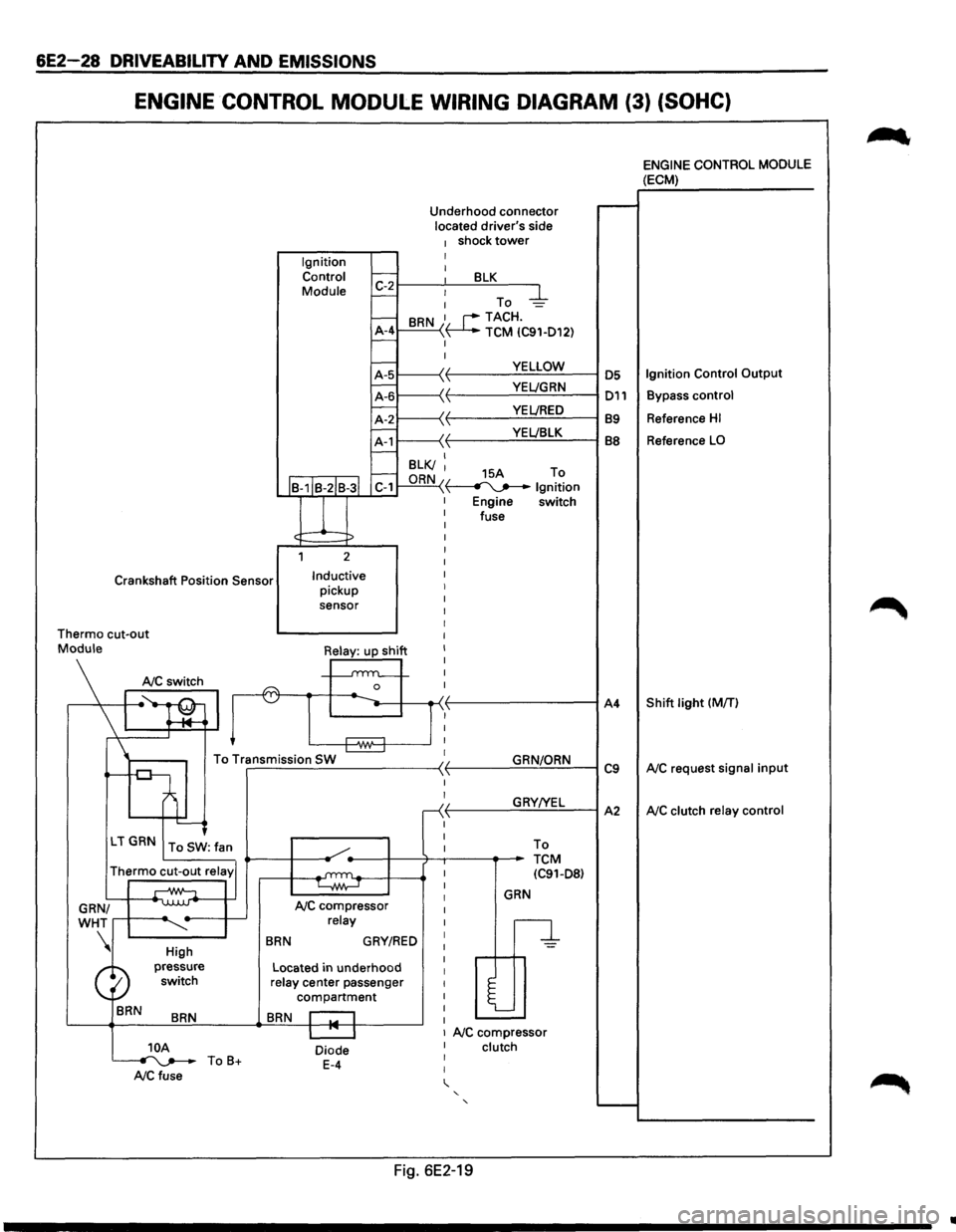
6E2-28 DRIVEABILITV AND EMISSIONS
ENGINE CONTROL MODULE WIRING DIAGRAM (3) (SOHC)
Ignition Control
Module Underhood
connector
located driver's side
1 shock tower I I 1:-2~--~~--~B~L~K~--~
- : To -4-
-BRN 1. r--TACH.
A-4 ~ TCM IC91-D12) -I
I
YELLOW
·~ YEL!GRN \ VEL/RED YEL!BLK
I--B-1IB-2IB-3l C-1
l
1 2
Crankshaft Position Sensor Inductive pickup
sensor I
I
I
I
Thermo cut-out I
I
I
I
I
n I
Mo\\I•Silj ~~
To Transmission SW ~ r-------------------~ -
'---<
LT GRN To SW: fan
Thermo cut-out relay'
GRN/
WHT
....--+-----~
BRN
High
pressure switch
BRN
NC compressor relay
BRN GRY/RED
Located in underhood relay center passenger
compartment
BRN r::-1
I
I
r
I
I
I
I
I
I
I
I
I
I
I
I
I
I
GRN/ORN
GRY!YEL To
TCM IC91-D8)
GRN
n
l
I I 1 NC compressor 10A ~ToB+ NCfuse
Diode E-4
I clutch I
I
' ' '
Fig. 6E2-19
A4
C9
A2
~
ENGINE CONTROL MODULE (ECM)
Reference HI
Reference LO
Shift light (MfT)
NC request signal input
NC clutch relay control
..
Page 725 of 1928
DRIVEABILITY AND EMISSIONS 6E2-29
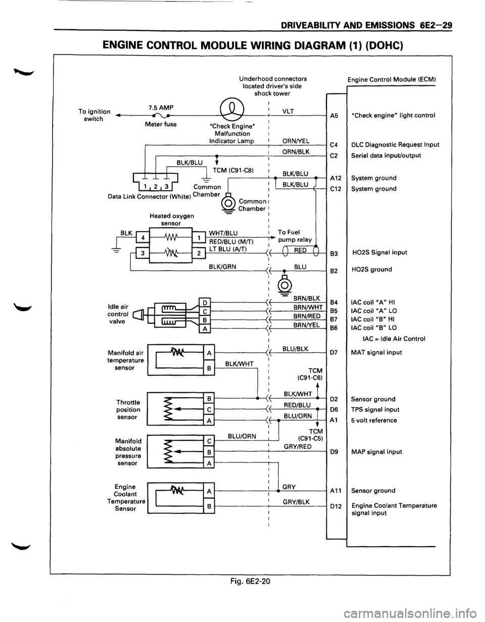
ENGINE CONTROL MODULE WIRING DIAGRAM (1) (DOHC)
Underhood connectors
located driver's side
shock
tower
To ignition
switch 7.5AMP ,.... ~ ®
I
I
Meter fuse I "Check Engine" I Malfunction I Indicator Lamp I
I
'
I 8LK/8LU I
D
I l TCM (C91-C8) 1
~ 1 2 ~ ~ co.;;mo~~ : ata Link Connector (White) Chamber 1 0 Common1 Chamber 1 Heated oxygen -= I
rg
=F
leair s ontrol C] alve
ld c v
M
te anifold
air
mperature sensor
Throttle position sensor
Manifold absolute pressure sensor
Engine
Coolant
T emperature
Sensor
sensor I
I
-A/IN-1:'1 WHT/8LU I
~ RED/8LU (M/TI I
~ ""21 L T 8LU (A/TI II ....::....1 ,1,
8LK/GRN :,
I
I
I
I
cam l:
I
I
Au A )I y"-\1 r--
8 8LK/WHT I I
I
I
I
8 ~ 1--II
~ r£ \ 'I A ,1,
8LU/ORN I
r£ ~ I
8 ~ f--I A I
I
I
_A& a A I y"-I r--I 8 I
I
I
Fig. 6E2-20
VLT
ORNNEL
ORN/8LK
8LK/8LU
I 8LK/8LU
To Fuel
pump relay
( ) RED ( v v
8LU
~ -8RN/8LK
8RN/WHT
8RN/RED
8RNNEL
8LU/8LK
TCM (C91-C6)
8LK/WHT !
RED/8LU
8LU/ORN
TCtM
(C91-C5)
GRY/RED
GRY
GRY/8LK Engine
Control
Module (ECMI
.-----
AS "Check engine" light control
C4 DLC Diagnostic Request lnpu
C2 Serial data input/output
A12 System ground
C12 System ground
83
H02S Signal input
82 H02S ground
84
lAC coil "A" HI
85 lAC coil "A" LO
87 lAC coil "8" HI
86 lAC coil "8" LO
lAC = Idle Air Control
D7 MAT signal input
D2 Sensor ground
D6 TPS signal input
A1 5 volt reference
D9 MAP signal input
A11 Sensor ground
D12 Engine Coolant Temperatur e signal input
......__
Page 726 of 1928
6E2-30 DRIVEABILITY AND EMISSIONS
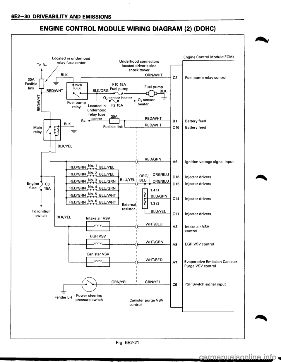
ENGINE CONTROL MODULE WIRING DIAGRAM (2) (DOHC)
Located in underhood Engine Control Module(ECM)
T B relay
fuse center Underhood connectors
o + located
driver's side r--. / shock tower
/ I BLK.---+-I_: ~==-----------+-: __ O_R_N...:./W_H_T_--1 C3 Fuel pump relay control
Fusible
= tti F10 15A 1
30A
I' k I 1 Fuel pump In REO/WHT BLK/ORG Fu:.._pu~
~ ~-T 02 sensor heater :
0 _ ~ I ~ 2 sensor -<. Fuel pump ~ lh @ relay Located in F2 10A 1 eater
a:'---underhood
relay fuse I
BLK 30A
1 B+ _..;c:..::ec:..:n-=.:te:.:..r_-1 REO/WHT B1 Battery
feed
Fusible link
lL---,--1 _ _:.:R:.=E-==O'-'fW:..:..:....:H-=-T---i C16 Battery feed Main relay
BLK/YEL I
I
I
I
I
I
I
L---~--------------<)1 REO/GRN ,1, A6
Engine ') CB fuse 15A
To ignition switch
REO/GRN No. 1
BLU/YEL I
REO/GRN No.2 BLU/YEL : ORG/ ORG/BLU 016
015
REO/GRN No.3 BLU/GRN
BLU/YEL }1 BLU l ORG/BLU L....::-=-=.:...=.:._.._ __ -<
REO/GRN No.4
BLU/GRN \'
REO/GRN No. 5
BLU/WHT
REO/GRN No. 6 BLU/WHT I
I
External1 resistor 1 I
1.4 n
t-+--B_L-'U/_G_R_N--1 C
14
1.3Q
'---=B:..::L:..::U_:_IY;_:E:.:L~ C 11 BLK/YEL Intake air VSV I
I
l
I I t.__-1~-----< t--...:...W:..:.H.:....:.T.:...::/B:..::Lc::.U_-1 A
3
I
I
I
EGRVSV
'---111 ____ -<' (-_...:...W.:....:.H.:....:.T.:...c/G=-R_N_-1 AB
Canister VSV 1
I 1
/ WHT/REO I '---1~-----<,f--,--"------1 A7 ~------~ I I I I
~r---G~RN~/Y~E_L __ 1 __ G~R_N...:.!Y_EL_~ C 6
Fender
LH Power steering
pressure switch Canister purge VSV
control
Fig. 6E2-21
Ignition voltage signal input
Injector drivers
Injector drivers
Injector drivers
Injector drivers
Intake air VSV
control
EGR VSV control
Evaporative Emission Canister
Purge VSV control
PSP Switch signal input
1111