charging ISUZU TROOPER 1995 Service Manual
[x] Cancel search | Manufacturer: ISUZU, Model Year: 1995, Model line: TROOPER, Model: ISUZU TROOPER 1995Pages: 1928
Page 1413 of 1928
STARTER SWITCH
Refer to "START AND CHARGING" in this section.
WINDSHIELD WIPER & WASHER
SWITCH
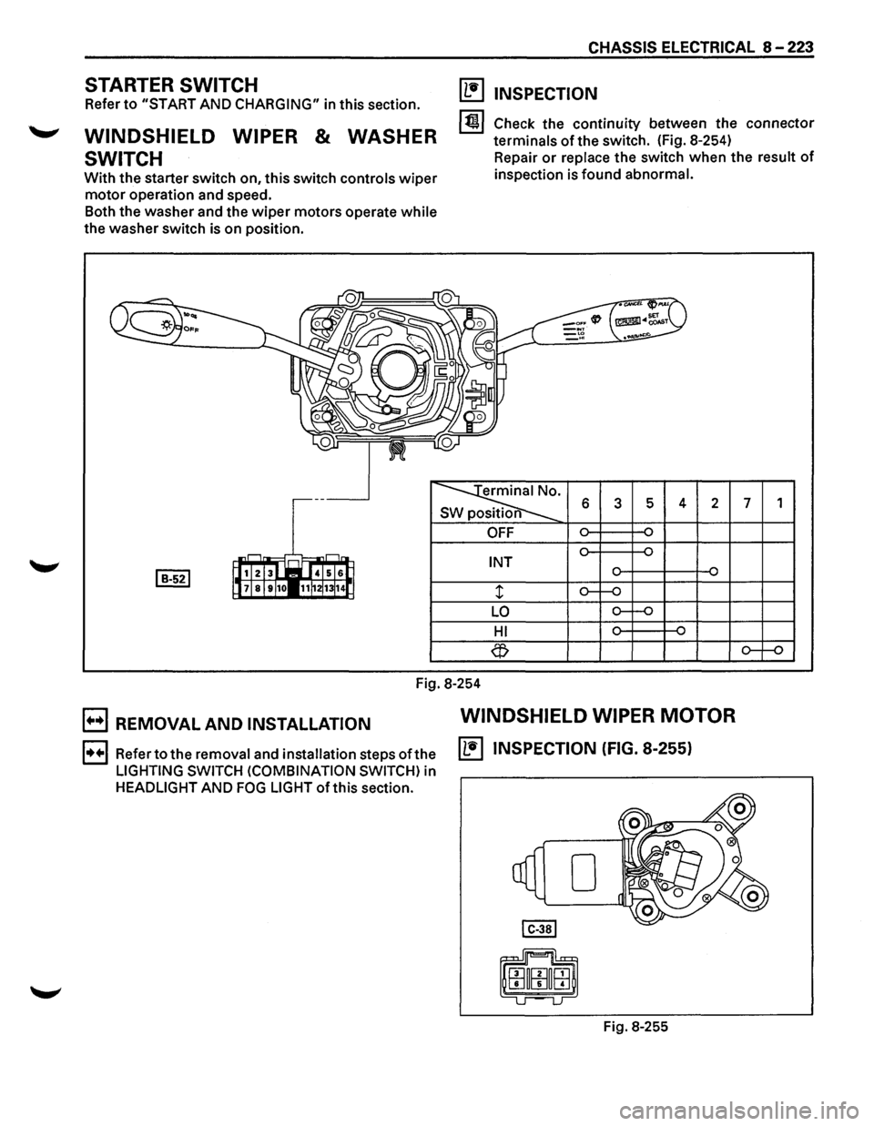
With the starter switch on, this switch controls wiper
motor operation and speed.
Both the washer and the
wiper motors operate while
the washer switch is on position.
CHASSIS ELECTRICAL 8 -223
(1!1 INSPECTION
1~1 Check the continuity between the connector
terminals
of the switch. (Fig. 8-254)
Repair
or replace the switch when the result of
inspection is found abnormal.
erminal No.
SW position 6 3 5 4 2 7 1
OFF
INT
LO
HI
Fig.
8-254
B REMOVAL AND INSTALLATION WINDSHIELD WIPER MOTOR
1••1 Refer to the removal and installation steps ofthe IL•IINSPECTION (FIG. 8-255)
LIGHTING SWITCH (COMBINATION SWITCH) in
HEADLIGHT AND FOG LIGHT ofthis section.
Fig. 8-255
Page 1432 of 1928
8-242 CHASSIS ELECTRICAL
STARTER SWITCH
Refer to "START AND CHARGING" of this section.
HEADLIGHT WIPER SWITCH (FIG. 8-
286)
Fig. 8-286
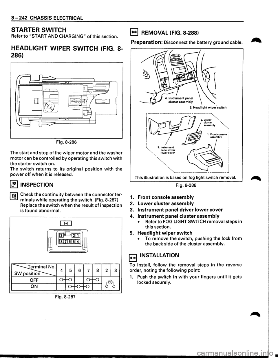
The start and stop
of the wiper motor and the washer
motor can be controlled by operating this switch with
the starter switch on.
The switch returns to its
original position with the
power off when it is released.
(1!] INSPECTION
rfiil Check the continuity between the connector ter
L:::.I minals while operating the switch. (Fig. 8-287)
Replace the switch when the result of inspection
is
found abnormal.
[ill
[I
roo8___8tillJ1
lsl7lslsi4IJ ill
' )
~· s 4 5 6 7 8 2 1 3
OFF o--o o-f-o
~ ON o-f-0--f-0
Fig. 8-287
B REMOVAL (FIG. 8-288)
Preparation: Disconnect the battery ground cable. ~
This illustration is based on fog light switch removal.
Fig. 8-288
1.
Front console assembly
2. Lower cluster assembly
3. Instrument panel driver lower cover
4. Instrument panel cluster assembly
• Refer to FOG LIGHT SWITCH removal steps in
this section.
5.
Headlight wiper switch
• To remove the switch, pushing the lock from
the back side of the cluster assembly.
B INSTALLATION
To install, follow the removal steps in the reverse
order, noting the
following point:
1. Push the switch in with your fingers until it gets
locked securely.
•
Page 1454 of 1928
8-264 CHASSIS ELECTRICAL
STARTER SWITCH
Refer to "START AND CHARGING" in this section.
DOOR MIRROR SWITCH ASSEMBLY
(CONTROL SWITCH, FOLDING
SWITCH
AND DEFOGGER SWITCH)
(FIG. 8-305)
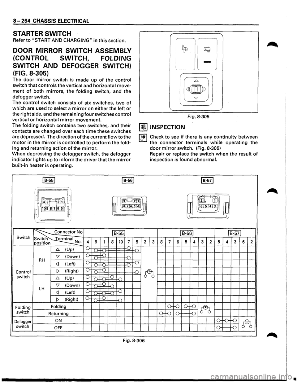
The door mirror switch is made up of the control
switch that controls the vertical and horizontal move
ment of both mirrors, the folding switch, and the
defogger switch.
The control switch consists of six switches, two of
which are used to select a mirror on either the left or
the right side, and the remaining four switches control
vertical or horizontal mirror movement.
The folding switch contains two switches, and their
contacts are changed over each time these switches
are depressed. The direction of the current flow to the
motor in the mirror is controlled to perform the fold
ing and returning action of the mirror.
When depressing the defogger switch, the defogger
indicator lights up to inform the driver that the mirror
built-in heater is operating.
I B-551 I B-561
i I I
!;l ~
LJ -J
I
I[~(@)~] J
Fig. 8-305
[!) INSPECTION
IL•I Check to see if there is any continuity between
the connector terminals while operating the
door mirror switch. (Fig. 8-306)
Repair or replace the switch when the result of
inspection is found abnormal.
I B-571
r .·~·· I ~ru·l
~~J!]}I ~ rroo~~l]
i !)~~1,1
a m
I ~ I ffi ;!sl7l6lsl41 ~ l~ lll"L•I'J'I•J ~~~
~' I J )
~0 ls-ssl IB-561 IB-571 Switch
N 4 9 1 8 10 7 5 2 3 8 7 6 5 4 3 2 5 4 3 6 2 o.
6. (Up) ~ ).. ...( ) .(")
'7 (Down) 0 c .) D RH c _.)
~ switch 6. (Up) c ~ -o ()-f-(l-
'7 (Down) 0 ( ) D LH c _.)
Folding Folding o-f-0 o--()
~ switch
Returning ()-Lo 0 0
Defogger ON o-'-0-
0
~ switch OFF 0 D
Fig. 8-306
•
Page 1474 of 1928
8-284 CHASSIS ELECTRICAL
ANTI-THEFT INDICATOR
~ INSPECTION
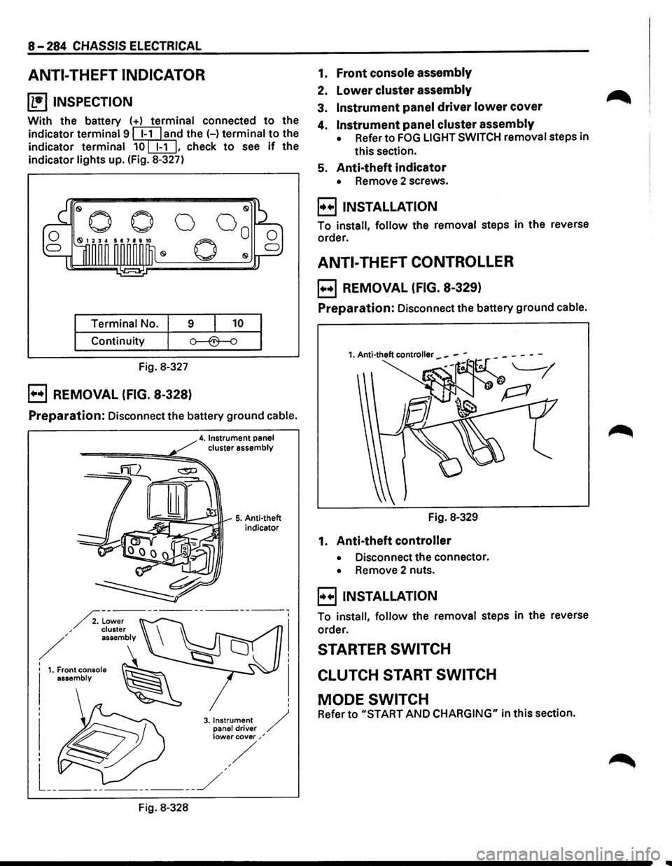
With the battery (+) terminal connected to the
indicator
terminal 9 ~l'ld the H terminal to the
indicator
terminal 10[EIJ, check to see if the
indicator
lights up. (Fig. 8-327)
Terminal No. 9 10
Continuity
Fig. 8-327
B REMOVAL (FIG. 8-328)
Preparation: Disconnect the battery ground cable.
4. Instrument panel cluster assembly
-====-==============~!!;!;::,..
Fig. 8-328
5. Anti-theft
indicator
1. Front console assembly
2. lower cluster assembly
3. Instrument panel driver lower cover
4. Instrument panel cluster assembly
• Refer to FOG LIGHT SWITCH removal steps in
this section.
5. Anti-theft indicator
• Remove 2 screws.
B INSTALLATION
To install, follow the removal steps in the reverse
order.
ANTI-THEFT CONTROLLER
B REMOVAL (FIG. 8-329)
Preparation: Disconnect the battery ground cable.
Fig. 8-329
1. Anti-theft controller
• Disconnect the connector.
• Remove 2 nuts.
B INSTALLATION
To install, follow the removal steps in the reverse
order.
STARTER SWITCH
CLUTCH START SWITCH
MODE SWITCH
Refer to "START AND CHARGING" in this section.
Page 1505 of 1928
STARTER SWITCH
Refer to "START AND CHARGING" in this section.
'--LIGHTING SWITCH/DIMMER •
PASSING SWITCH/HEADLIGHT
Refer to "HEADLIGHT AND FOG LIGHT" in this sec-
tion.
TURN SIGNAL SWITCH
Refer to "TURN SIGNAL LIGHT, HAZARD WARNING
LIGHT, CORNERING LIGHT, BACKUP LIGHT AND
HORN" in this section.
ILLUMINATION CONTROLLER
Refer to the "FRONT SIDE MARKER LIGHT, PARKING
LIGHT, TAILLIGHT, LICENSE PLATE LIGHT AND ILLU
MINATION LIGHT"
in this section.
CHASSIS ELECTRICAL 8-315
Page 1544 of 1928
8-354 CHASSIS ELECTRICAL
STARTER SWITCH
Refer to "Start and Charging" in this section.
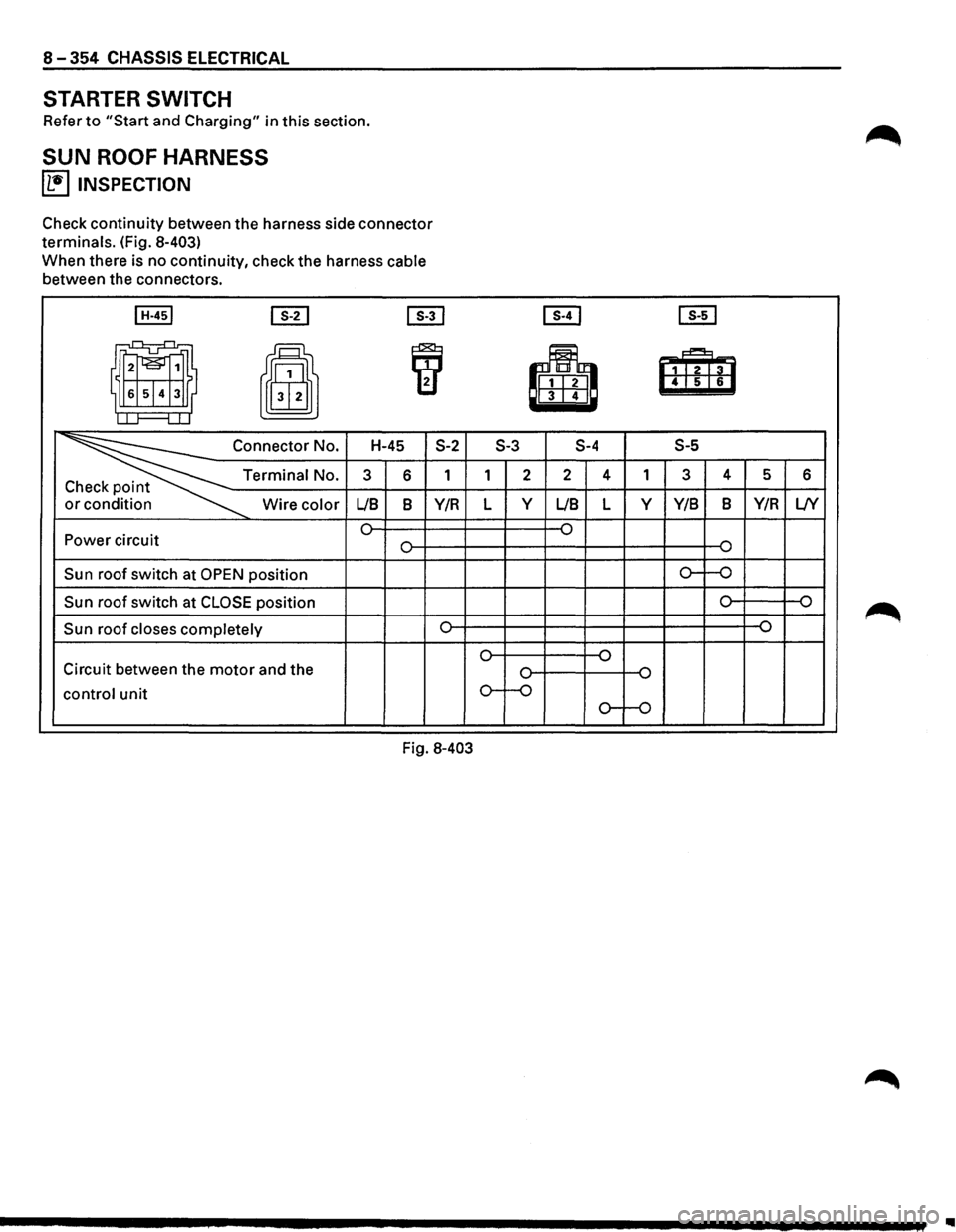
SUN ROOF HARNESS
~ INSPECTION
Check continuity between the harness side connector
terminals. (Fig. 8-403)
When there is no continuity, check the harness cable
between the connectors.
I H-451 em [IT]
II I
~
~ H-45 S-2 ~onnector No.
C Terminal No. 3 6 1 t
or Wire color LIB B Y/R
0 Power circuit 0
Sun roof switch
at OPEN position
Sun roof switch at CLOSE position
Sun roof closes completely
Circuit between the motor and the
control unit
Fig. 8-403
[EJ [ill
!I!
BmB 6
S-3
S-4 S-5
1 2 2 4 1 3 4 5 6
L y LIB L y Y/B B Y/R L/Y
{) ,... .....,
o--o
{)
,... .....,
0 {) ,...
,...
o-~
.....,
o--o
IIIII
Page 1570 of 1928
8-380 CHASSIS ELECTRICAL
STARTER SWITCH
Refer to "START AND CHARGING" in this section.
SEAT HEATER SWITCH
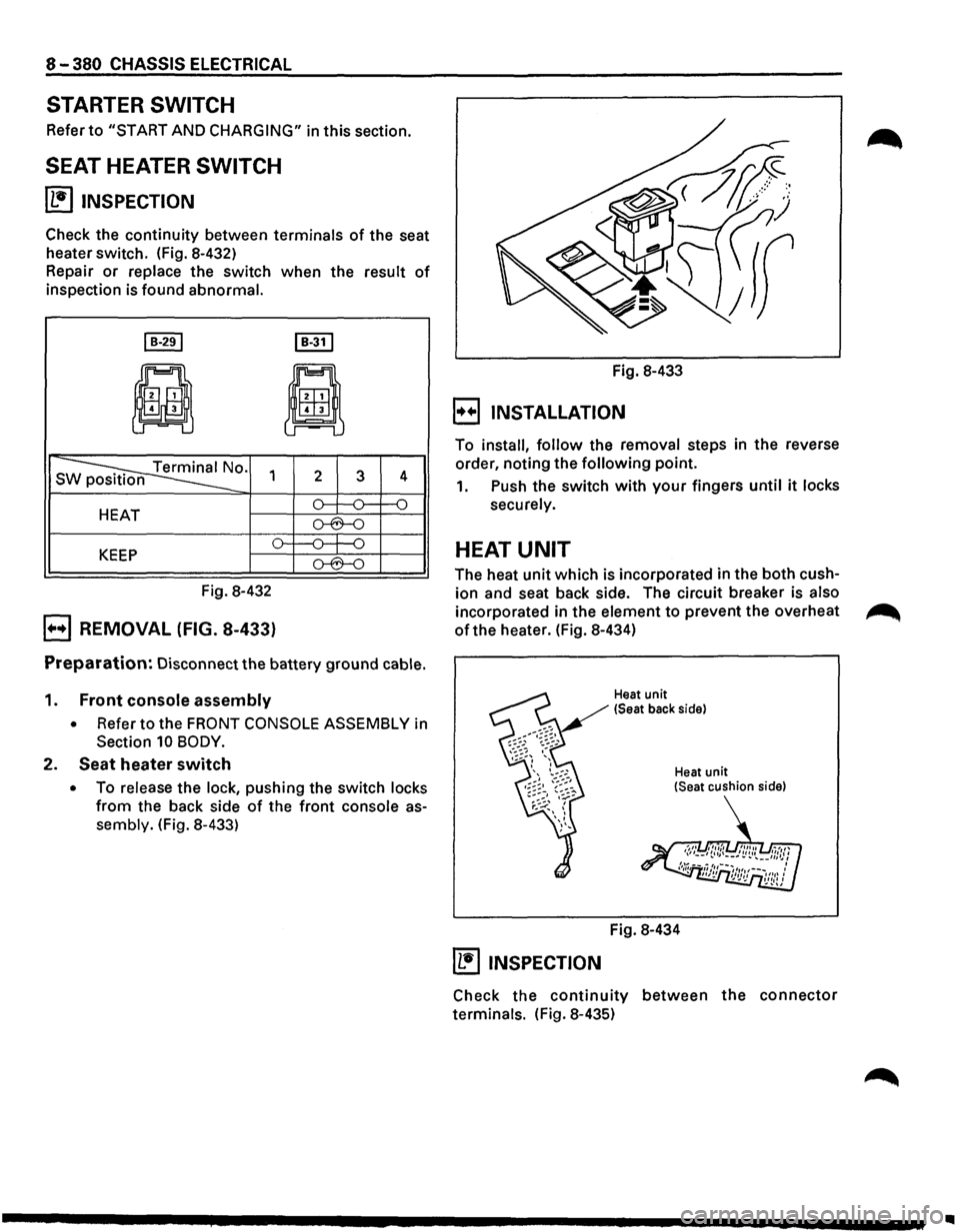
~ INSPECTION
Check the continuity between terminals of the seat
heater switch. (Fig. 8-432)
Repair
or replace the switch when the result of
inspection is found abnormal.
I B-291 I B-31 I
ji
8
s ~0. 1 2 3 4
HEAT o--:---0= f--0
o-6--0
o---0---j-0 KEEP o-6--0
Fig. 8-432
B REMOVAL (FIG. 8-433)
Preparation: Disconnect the battery ground cable.
1. Front console assembly
• Refer to the FRONT CONSOLE ASSEMBLY in
Section 10 BODY.
2. Seat heater switch
• To release the lock, pushing the switch locks
from the back side of the front console as
sembly. (Fig. 8-433) Fig.
8-433
B INSTALLATION
To install, follow the removal steps in the reverse
order, noting the
following point.
1. Push the switch with your fingers until it locks
securely.
HEAT UNIT
The heat unit which is incorporated in the both cush
ion and seat back side. The circuit breaker is also
incorporated in the element to prevent the overheat ~
of the heater. (Fig. 8-434)
Heat unit
(Seat back side)
Heat
unit (Seat cushion side)
Fig. 8-434
~ INSPECTION
Check the continuity between the connector
terminals. (Fig. 8-435)
..
Page 1700 of 1928
9J-76 Supplemental Restraint System
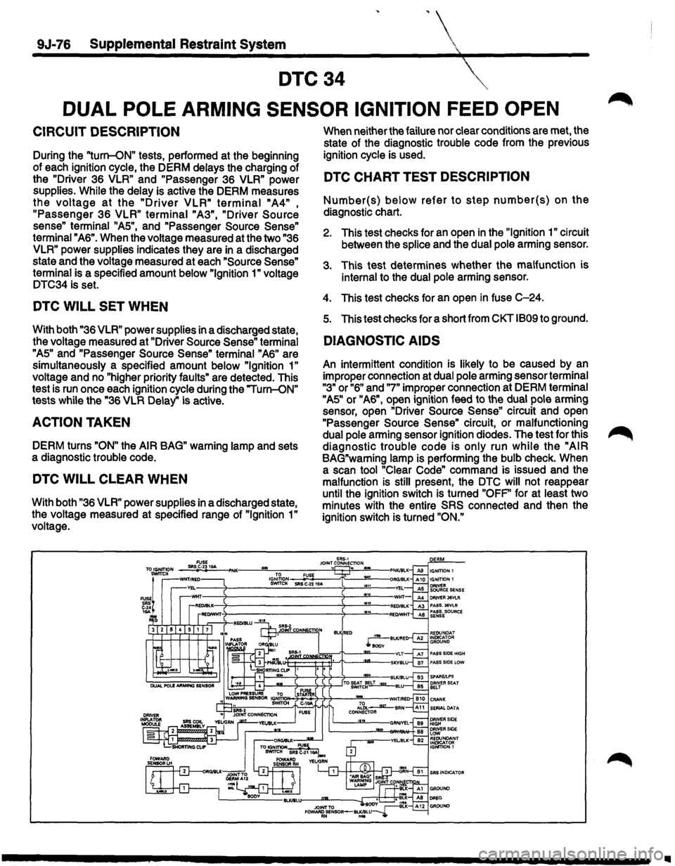
DTC34
DUAL POLE ARMING SENSOR IGNITION FEED OPEN
CIRCUIT DESCRIPTION
During the "turn-ON" tests, performed at the beginning
of each ignition cycle, the DERM delays the charging of
the
"Driver 36 VLR" and "Passenger 36 VLR" power
supplies.
While the delay is active the DERM measures
the voltage at the "Driver VLR" terminal "A4" ,
"Passenger 36 VLR" terminal "A3", "Driver Source
sense" terminal "AS", and "Passenger Source Sense"
terminal "A6". When the voltage measured at the two "36
VLR" power supplies indicates they are in a discharged
state and the voltage measured at each
"Source Sense"
terminal is a specified amount below "Ignition 1" voltage
DTC34 is set.
DTC WILL SET WHEN
With both "36 VLR" power supplies in a discharged state,
the voltage measured at "Driver
Source Sense" terminal
"AS" and "Passenger Source Sense" terminal "A6" are
simultaneously a specified amount below
"Ignition 1"
voltage and no "higher priority faults" are detected. This
test is run once each ignition cycle during the "Turn-ON"
tests while the "36
VLR Delay" is active.
ACTION TAKEN
DERM turns "ON" the AIR BAG" warning lamp and sets
a diagnostic trouble code.
DTC WILL CLEAR WHEN
With both "36 VLR" power supplies in a discharged state,
the voltage measured at specified range of
"Ignition 1"
voltage. When
neither the failure nor clear conditions are met, the
state of the diagnostic trouble code from the previous
ignition cycle is used.
DTC CHART TEST DESCRIPTION
Number(s) below refer to step number(s) on the
diagnostic chart.
2. This test checks for an open in the "Ignition 1" circuit
between the
splice and the dual pole arming sensor.
3. This test determines whether the malfunction is
internal to the dual pole arming sensor.
4. This test checks for an open in fuse C-24.
s. This test checks for a short from CKT 1809 to ground.
DIAGNOSTIC AIDS
An intermittent condition is likely to be caused by an
improper connection at dual pole arming sensor terminal
"3" or "6" and "7" improper connection at DERM terminal
"AS" or "A6", open ignition feed to the dual pole arming
sensor, open "Driver
Source Sense" circuit and open
"Passenger
Source Sense" circuit, or malfunctioning
dual pole arming sensor ignition diodes. The test for this
diagnostic trouble code is only run while the "AIR
BAG"warning lamp is performing the bulb check. When
a scan tool "Clear Code" command is issued and the
malfunction
is still present, the DTC will not reappear
until the ignition switch is turned
"OFP' for at least two
minutes with the entire
SRS connected and then the
ignition switch is turned
"ON."
Ill
Page 1708 of 1928
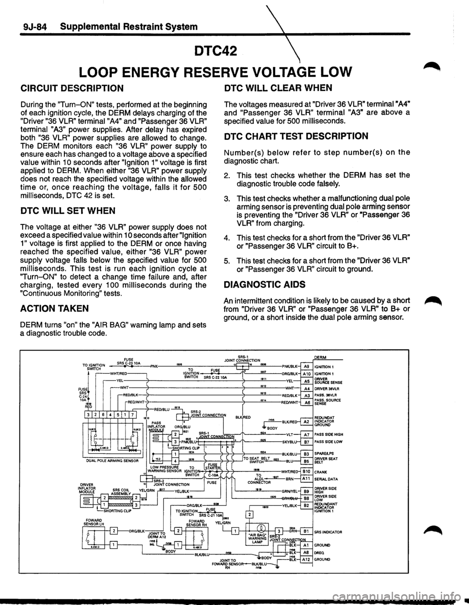
9J-84 Supplemental Restraint System
DTC42
LOOP ENERGY RESERVE VOLTAGE LOW
CIRCUIT DESCRIPTION
During the "Turn-ON" tests, performed at the beginning
of each ignition
cycle, the DERM delays charging of the
"Driver "36
VLR" terminal "A4" and "Passenger 36 VLR"
terminal
"A3" power supplies. After delay has expired
both "36
VLR" power supplies are allowed to change.
The DERM monitors each
"36 VLR" power supply to
ensure each has changed to a
voltage above a specified
value within 1 0 seconds after "Ignition 1" voltage is first
applied to DERM. When either "36 VLR" power supply
does not reach the specified voltage within the allowed
time or, once reaching the voltage, falls it for 500
milliseconds, DTC 42 is set.
DTC WILL SET WHEN
The voltage at either "36 VLR" power supply does not
exceed a specified
value within 10 seconds after "Ignition
1" voltage is first applied to the DERM or once having
reached the specified
value, either "36 VLR" power
supply voltage falls below the specified value for 500
milliseconds.
This test is run each ignition cycle at
"Turn-ON" to detect a change time failure and, after
charging, tested every
100 milliseconds during the
"Continuous Monitoring" tests.
ACTION TAKEN
DERM turns "on" the "AIR BAG" warning lamp and sets
a diagnostic
trouble code.
DTC WILL CLEAR WHEN
The voltages measured at "Driver 36 VLR" terminal "A4"
and "Passenger 36
VLR" terminal "A3" are above a
specified
value for 500 milliseconds.
DTC CHART TEST DESCRIPTION
Number(s) below refer to step number(s) on the
diagnostic chart.
2. This test checks whether the DERM has set the
diagnostic
trouble code falsely.
3. This test checks whether a malfunctioning dual pole
arming sensor is preventing dual pole arming sensor
is preventing the "Driver 36
VLR" or "Passenger 36
VLR" from charging.
4. This test checks for a short from the "Driver 36 VLR"
or "Passenger 36 VLR" circuit to 8+.
5. This test checks for a short from the "Driver 36 VLR"
or "Passenger 36 VLR" circuit to ground.
DIAGNOSTIC AIDS
An intermittent condition is likely to be caused by a short
from "Driver 36
VLR" or "Passenger 36 VLR" to B+ or
ground, or a short inside the
dual pole arming sensor.
SRS~1 JOINT CONNECTION IBOii 12 1G IGNITION 1
DRIVER 36VLR PASS.31VLR PASS. SOURCE SENSE
REDUNDAT INDICATOR GROUND
PASS SIDE HIGH PASS SIDE LOW
SPAREilPS
SERIAL DATA
DRIVER SIDE HIGH DRIVER SIDE LOW REDUNDANT INDICATOR IGNmON 1
1111
Page 1730 of 1928
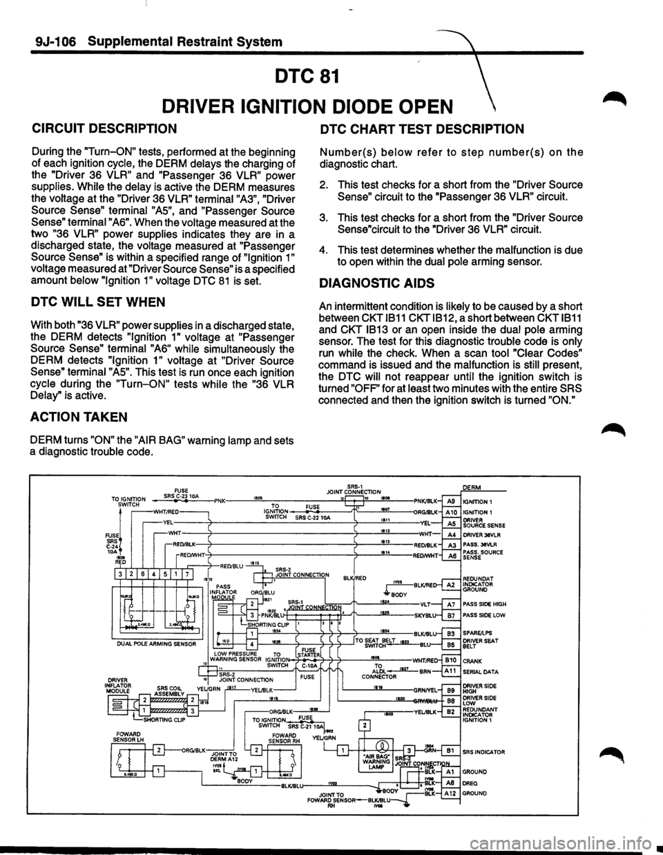
9J-106 Supplemental Restraint System
DTC81
DRIVER IGNITION DIODE OPEN
CIRCUIT DESCRIPTION
During the "Turn-ON" tests, performed at the beginning
of each ignition
cycle, the DERM delays the charging of
the "Driver
3S VLR" and "Passenger 3S VLR" power
supplies. While the delay is active the DERM measures
the
voltage at the "Driver 3S VLR" terminal "A3", "Driver
Source
Sense" terminal "AS", and "Passenger Source
Sense" terminal "AS". When the voltage measured at the
two
"3S VLR" power supplies indicates they are in a
discharged state, the
voltage measured at "Passenger
Source
Sense" is within a specified range of "Ignition 1"
voltage
measured at "Driver Source Sense" is a specified
amount
below "Ignition 1" voltage DTC 81 is set.
DTC WILL SET WHEN
With both "3S VLR" power supplies in a discharged state,
the DERM detects
"Ignition 1" voltage at "Passenger
Source
Sense" terminal "AS" while simultaneously the
DERM detects
"Ignition 1" voltage at "Driver Source
Sense" terminal "AS". This test is run once each ignition
cycle during the "Turn-ON" tests while the "3S VLR
Delay"
is active.
ACTION TAKEN
DERM turns "ON" the "AIR BAG" warning lamp and sets
a diagnostic
trouble code.
DTC CHART TEST DESCRIPTION
Number(s) below refer to step number(s) on the
diagnostic chart.
2. This test checks for a short from the "Driver Source
Sense" circuit to the "Passenger 3S VLR" circuit.
3. This test checks for a short from the "Driver Source
Sense"circuit to the "Driver
3S VLR" circuit.
4. This test determines whether the malfunction is due
to open within the
dual pole arming sensor.
DIAGNOSTIC AIDS
An intermittent condition is likely to be caused by a short
between
CKT 1811 CKTIB12, a short between CKT 1811
and CKT 1813 or an open inside the dual pole arming
sensor. The test for this diagnostic
trouble code is only
run while the check. When a scan tool "Clear Codes"
command is issued and the malfunction is still present,
the
DTC will not reappear until the ignition switch is
turned
"OFF" for at least two minutes with the entire SRS
connected and then the ignition switch is turned "ON."
SRS-1 FUSE JOINT CONNECTION TOS~~~:?N -_;:,;SR-"
IGNmON ~-=-------"T"---""'1107<----SWrTCH SRS C-22 10A 1111
1112 DRIVER 36VLR PASS.36VLR PASS. SOURCE SENSE
REOUNOAT INDICATOR GROUND
PASS SIDE HIGH
PASS SIDE LOW
SERIAL DATA
SRS INDICATOR
•