differential ISUZU TROOPER 1995 Service Manual
[x] Cancel search | Manufacturer: ISUZU, Model Year: 1995, Model line: TROOPER, Model: ISUZU TROOPER 1995Pages: 1928
Page 301 of 1928
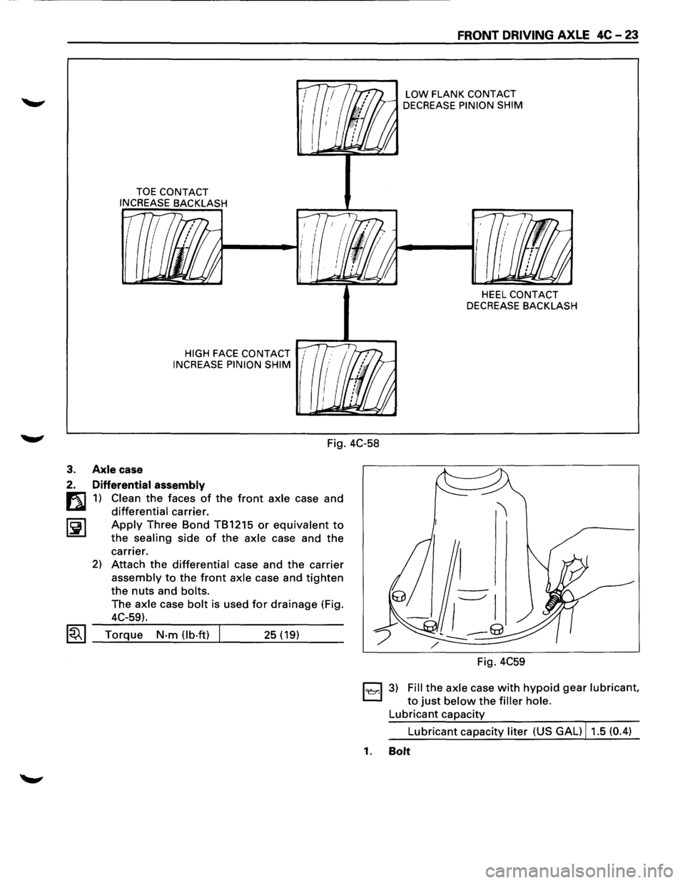
TOE CONTACT
INCREASE BACKLASH
HIGH FACE CONTACT 1
INCREASE PINION SHIM
FRONT DRIVING AXLE 4C-23
LOW FLANK CONTACT
DECREASE PINION SHIM
HEEL CONTACT
DECREASE BACKLASH
Fig. 4C-58
3. Axle case
2. Differential assembly
m 1) Clean the faces of the front axle case and
Lail differential carrier.
~~I Apply Three Bond TB1215 or equivalent to
the sealing side of the axle case and the
carrier.
2) Attach the differential case and the carrier
assembly to the front axle case and tighten
the nuts and bolts.
The axle case bolt is used for drainage (Fig.
4C-59).
~~~ Torque N-m (lb·ft) 25 (19)
Fig.
4C59
1~1 3) Fill the axle case with hypoid gear lubricant,
to just below the filler hole.
Lubricant capacity
Lubricant capacity liter (US GAL) 11.5 (0.4)
1. Bolt
Page 302 of 1928
4C-24 FRONT DRIVING AXLE
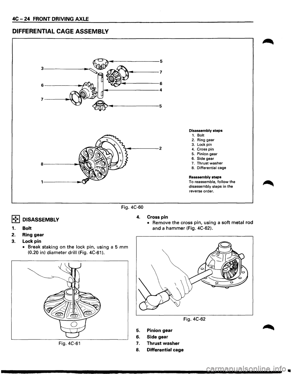
DIFFERENTIAL CAGE ASSEMBLY
~~~------------6
~----------------4
Fig. 4C-60
4. Cross pin
Disassembly steps 1. Bolt 2. Ring gear
3. Lock pin 4. Cross pin 5. Pinion gear 6. Side gear 7. Thrust washer 8. Differential cage
Reassembly steps
To reassemble, follow the disassembly steps in the
reverse order.
l•!•l DISASSEMBLY
1. Bolt
• Remove the cross pin, using a soft metal rod
and a hammer (Fig. 4C-62).
2. Ring
gear
3. Lock pin
• Break staking on the lock pin, using a 5 mm
(0.20 in) diameter drill (Fig. 4C-61 ).
Fig. 4C-61
Fig. 4C-62
5. Pinion gear
6. Side gear
7. Thrust washer
8. Differential cage
•
Page 303 of 1928
![ISUZU TROOPER 1995 Service Manual (1!] INSPECTION AND REPAIR
Make necessary correction or parts replacement if
~ wear, damage, corrosion or any other abnormal
condition are found through inspection.
Check the
following part](/img/61/57183/w960_57183-302.png "ISUZU TROOPER 1995 Service Manual (1!] INSPECTION AND REPAIR
Make necessary correction or parts replacement if
~ wear, damage, corrosion or any other abnormal
condition are found through inspection.
Check the
following part")
(1!] INSPECTION AND REPAIR
Make necessary correction or parts replacement if
~ wear, damage, corrosion or any other abnormal
condition are found through inspection.
Check the
following parts.
• Ring gear, pinion gear
• Bearing
• Side gear, pinion gear, cross pin
• Differential cage, carrier
• Thrust washer
• Oil seal
Ring gear replacement
1) The ring gear should always be replaced with
the drive pinion as a set.
2) Clean the ring gear threaded holes to remove
the
locking agent.
~~~3) When installing the ring gear, apply LOCTITE
271 or equivalent to all the threaded area and
half of the unthreaded area of the bolt.
4) Discard used bolts and install new ones.
I~I __ T_o_rq~u_e __ N_·m~(l_b·_ft~l_IL_ ___ 1_0_8~(8_0_l __ __
5) Tighten the fixing bolts in a diagonal
sequence as illustrated (Fig. 4C-63).
Fig. 4C-63
H'ffil Clearance between the differential pinion and
L!l!l the cross pin measurement (Fig. 4C-64).
mm (in)
Standard Limit
0.06 -0.12 (0.002 -0.005)
0.2 (0.008)
FRONT DRIVING AXLE 4C-25
Fig. 4C-64
rfi:i1 Clearance between the side gear and the
L!l!l differential box (Fig. 4C-65)
mm (in)
Standard Limit
0.03 -0.10 (0.001 -0.004)
0.15
(0.006)
Side gear
Differential box
Fig. 4C-65
rfi:il Play in splines between the side gear and the
L!l!l axle shaft (Fig. 4C-66)
mm (in)
Standard Limit
0.08 -0.36
(0.003 -0.014) 0.5 (0.02)
Page 304 of 1928
4C -26 FRONT DRIVING AXLE
l•!•l REASSEMBLY
8. Differential cage
7. Thrust washer
6. Side gear
5. Pinion gear
Fig. 4C-66
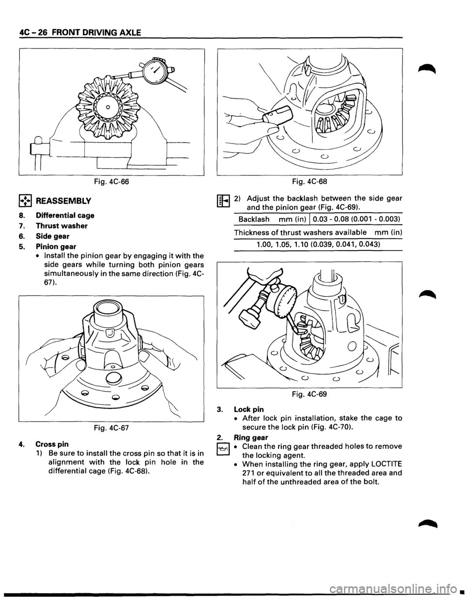
• Install the pinion gear by engaging it with the
side gears
while turning both pinion gears
simultaneously in the same direction (Fig. 4C-
67).
Fig. 4C-67
4. Cross pin
1) Be sure to install the cross pin so that it is in
alignment with the lock pin hole in the
differential cage (Fig. 4C-68). Fig.
4C-68
!EEl 2) Adjust the backlash between the side gear
and the
pinion gear (Fig. 4C-69).
Backlash
mm (in) I 0.03-0.08 (0.001 -0.003)
Thickness of thrust washers available mm (in)
1.00, 1.05, 1.10 (0.039, 0.041, 0.043)
Fig. 4C-69
3. Lock pin
• After lock pin installation, stake the cage to
secure the lock pin (Fig. 4C-70).
2. Ring gear
1~1 • Clean the ring gear threaded holes to remove
the locking agent.
• When installing the ring gear, apply LOCTITE
271 or equivalent to all the threaded area and
half of the unthreaded area of the bolt.
•
Page 315 of 1928
FRONT DRIVING AXLE 4C-37
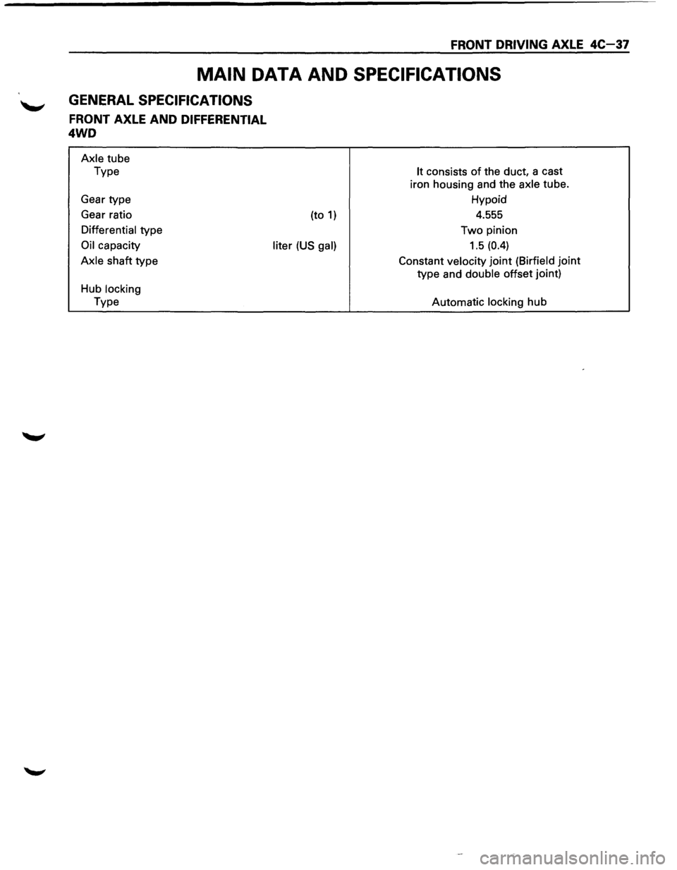
MAIN DATA AND SPECIFICATIONS
GENERAL SPECIFICATIONS
FRONT AXLE AND DIFFERENTIAL
4WD
Axle tube
Type
Gear type
Gear ratio
Differential type
Oil capacity
Axle shaft type
Hub locking
Type (to
1)
liter (US gal)
It consists of the
duct, a cast
iron housing and the axle tube.
Hypoid
4.555
Two pinion
1.5 (0.4)
Constant velocity joint (Birfield joint
type and double offset joint)
Automatic locking
hub
Page 317 of 1928
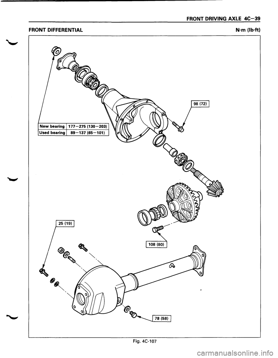
FRONT DIFFERENTIAL
New bearing 177-275 (130-203)
Used bearing 89-137 (65-101)
FRONT DRIVING AXLE 4C-39
N·m (lb·ft}
Fig. 4C-107
Page 319 of 1928
FRONT DRIVING AXLE 4C-41
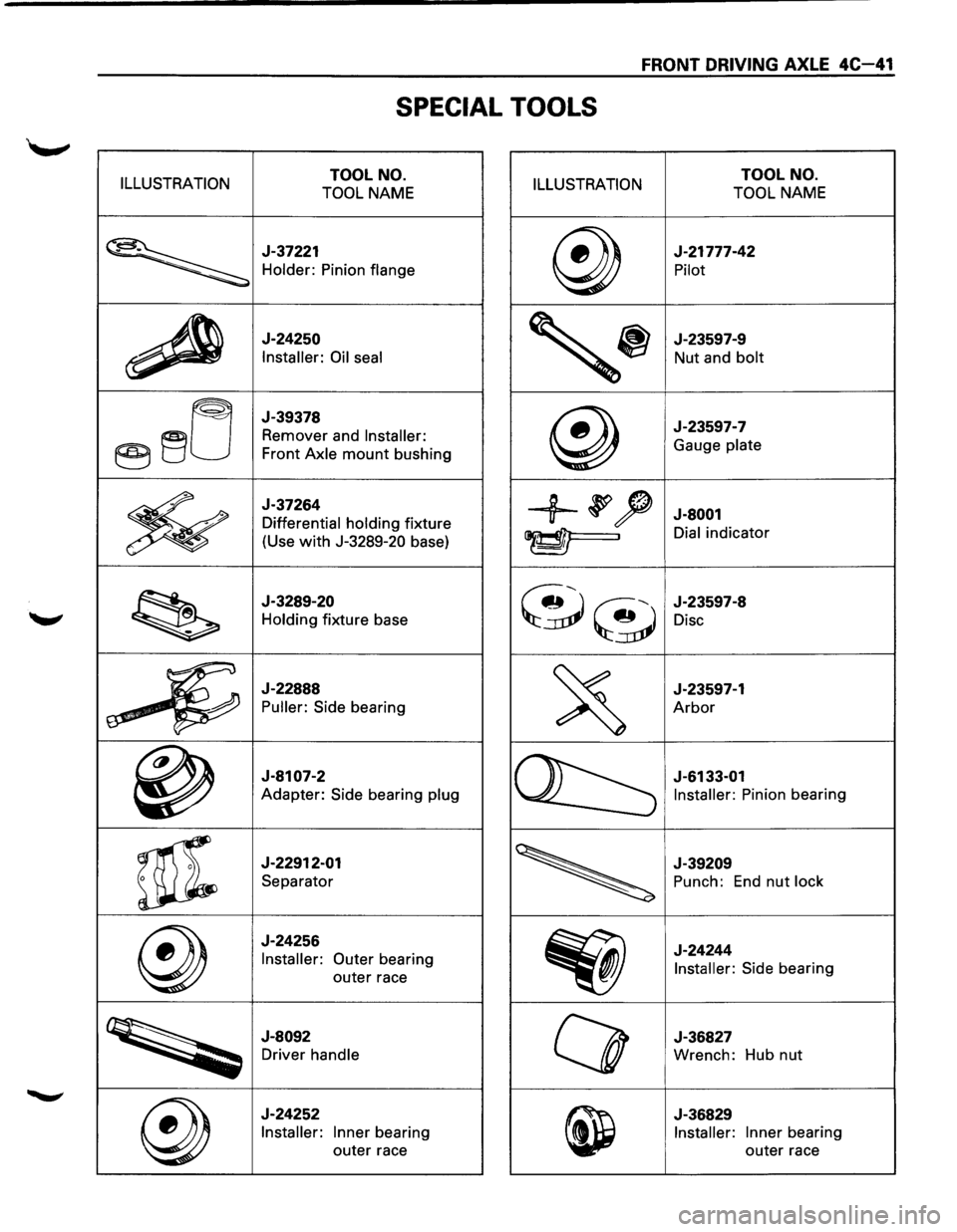
SPECIAL TOOLS
ILLUSTRATION TOOL NO.
TOOL NAME ILLUSTRATION TOOL NO.
TOOL NAME
~
J-37221
Holder: Pinion flange @)
J-21777-42
Pilot
~
J-24250
Installer: Oil seal
'~
J-23597-9
Nut and bolt
@~lj
J-39378
Remover and Installer:
Front Axle mount bushing @
J-23597-7
Gauge plate
*
J-37264
Differential holding fixture
(Use
with J-3289-20 base)
+~? J-8001
~. Dial indicator
~
J-3289-20
Holding fixture base ~~
J-23597-8
Disc
"'"~
t>'"""_j~
J-22888
Puller: Side bearing
~
J-23597-1
Arbor
~
J-8107-2
Adapter: Side bearing plug
~
J-6133-01
Installer: Pinion bearing
~
J-22912-01
Separator
~
J-39209
Punch: End nut lock
@
J-24256
Installer:
Outer bearing
outer race
Eiij)
J-24244
Installer: Side bearing
~
J-8092
Driver handle Q
J-36827
Wrench: Hub nut
@)
J-24252
Installer: Inner bearing
outer race
~
J-36829
Installer: Inner bearing
outer race
Page 329 of 1928
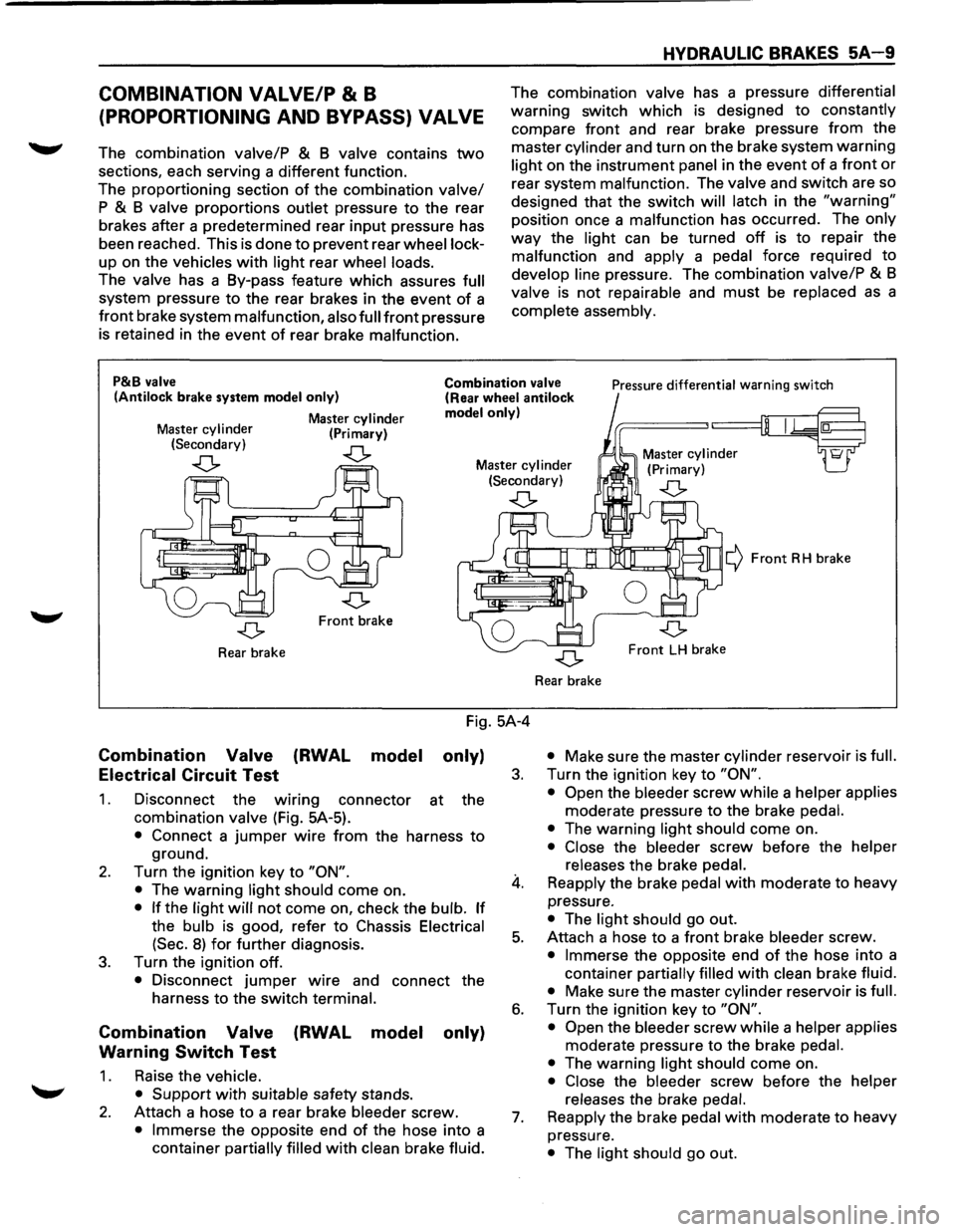
COMBINATION VALVE/P & B
(PROPORTIONING AND BYPASS) VALVE
The combination valve/P & B valve contains two
sections, each serving a different function.
The proportioning section
of the combination valve/
P & B valve proportions outlet pressure to the rear
brakes after a predetermined rear
input pressure has
been reached. This is done to prevent rear
wheel lock
up on the vehicles with light rear wheel loads.
The valve has a By-pass feature which assures full
system pressure to the rear brakes in the event of a
front brake system malfunction, also full front pressure
is retained in the event
of rear brake malfunction.
HYDRAULIC BRAKES 5A 9
The combination valve has a pressure differential
warning switch which is designed to constantly
compare front and rear brake pressure
from the
master
cylinder and turn on the brake system warning
light on the instrument panel in the event of a front or
rear system malfunction. The valve and switch are so
designed that the switch
will latch in the "warning"
position once a malfunction has occurred. The only
way the light can be turned off is to repair the
malfunction and
apply a pedal force required to
develop line pressure. The combination valve/P & B
valve is not repairable and must be replaced as a
complete assembly.
P&B valve
(Antilock brake system model only)
Master cylinder (Primary)
Combination valve (Rear wheel antilock model only)
Pressure differential warning switch
Master
cylinder (Secondary)
..(> ..(> Master cylinder (Secondary) Master
cylinder
(Primary)
..(> ..(>
Front brake
Rear brake
Combination Valve
Electrical Circuit Test (RWAL
model
Fig. 5A-4
only)
1.
2.
3.
Disconnect the wmng connector at the
combination
valve (Fig. 5A-5).
• Connect a jumper wire from the harness to
ground.
Turn the ignition key to
"ON".
•
The warning light should come on.
• If the light will not come on, check the bulb. If
the bulb is good, refer to Chassis Electrical
(Sec.
8) for further diagnosis.
Turn the ignition off.
• Disconnect jumper wire and connect the
harness to the switch
terminal.
Combination Valve (RWAL model only)
Warning
Switch Test
1. Raise the vehicle.
• Support
with suitable safety stands.
2. Attach a hose to a rear brake bleeder screw.
• Immerse the opposite end of the hose into a
container
partially filled with clean brake fluid.
3.
4.
5.
6.
7.
¢ Front RH brake
Front LH brake
Rear brake
• Make sure the master cylinder reservoir is full.
Turn the ignition key to "ON".
• Open
the bleeder screw while a helper applies
moderate pressure to the brake pedal.
•
The warning light should come on.
• Close the bleeder screw before the helper
releases
the brake pedal.
Reapply the brake pedal with moderate to heavy
pressure.
• The light should go out.
Attach a hose
to a front brake bleeder screw.
• Immerse the opposite end of the hose into a
container
partially filled with clean brake fluid.
• Make sure the master cylinder reservoir is full.
Turn the ignition key to "ON".
• Open
the bleeder screw while a helper applies
moderate pressure to the brake pedal.
•
The warning light should come on.
• Close the bleeder screw before the helper
releases
the brake pedal.
Reapply
the brake pedal with moderate to heavy
pressure.
• The light should go out.
Page 369 of 1928
REAR WHEEL ANTILOCK BRAKE SYSTEM 5A3-1
SECTION 5A3
REAR WHEEL ANTILOCK BRAKE SYSTEM
(RWAL}
w CAUTION:
• All brake attaching fasteners are an important attaching part in that they could affect performance of vital
parts and systems, and/or could result in major repair expense. They must be replaced with one of the same
part
number or with an equivalent part if replacement becomes necessary. Do not use replacement parts of
lesser quality or substitute design. Torque values must be used as specified during reassembly to assure
proper retention of these parts.
CONTENTS
Introduction . . . . . . . . . . . . . . . . . . . . . . . . . 5A3· 1
General Description . .
. . . . . . . . . . . . . . .
5A3· 1
Rear
Wheel Antilock (RWAL) Control
Parts Location . .
. . . . . . . . . . . . . . . . .
5A3· 5
System Diagram . .
. . . . . . . . . . . . . . . . . . . .
5A3· 6
Rear
Wheel Antilock (RWAL) System
Diagnostics . .
. . . . . . . . . . . . . . . . . . . . . .
5A3· 7
On-Vehicle Service . .
. . . . . . . . . . . . . . . . .
5A3·38
RWAL Electronic Brake Control
Module (EBCM) Replacement ....... 5A3-38
Antilock
(Isolation/Dump) Valve
Replacement ..................... 5A3-39
Speed Sensor Replacement
.......... 5A3-40
Main Data and Specifications ........... 5A3-41
Torque Specifications
............... 5A3-41
INTRODUCTION
This section deals with the complete diagnosis and
services
for vehicles equipped with rear wheel
antilock.
For service information regarding all other
components
of the brake system, refer to "Hydraulic
Brakes"
(Sec. SA), "Brake Booster System" (Sec. SA 1)
or "Disc Brakes" (Sec. SA2) of this Manual.
GENERAL DESCRIPTION
The rear wheel anti lock system (RWAL) is designed to
reduce rear wheel lock-up during a severe brake
application,
thus maintaining rear end stability. The
system functions
by regulating the rear hydraulic
brake line pressure. The pressure regulation is
accomplished
by an anti lock valve which is located on
the
front right side of engine room. The anti lock valve
is made up of two valves, a dump valve which releases
pressure into an accumulator and an isolation valve
which maintains rear brake pressure. The valve is
controlled
by a microcomputer which is part of the
Electronic Brake Control Module (EBCM). The
EBCM is mounted at the
front of the center
console. Under severe brake application, as pressure
is
applied to the brake pedal, the EBCM is designed to
permit the valve to do one of three functions or a
combination
of all three. The EBCM will allow the valve
to either maintain the same amount of hydraulic
pressure, release hydraulic pressure through the
dump valve into the accumulator or increase the
pressure by
pulsing the isolation valve.
The EBCM operates by receiving signals from the
speed sensor (which
is located in the differential
carrier), combination
valve and the brake light switch.
The RWAL system is connected
to the RWAL indicator
light located on the dash. An indication of the RWAL
operation and a
bulb check is performed each time the
ignition is turned
"ON". The indicator light will remain
on
for about two seconds. A RWAL system
malfunction is indicated if the RWAL indicator light
stays on, or comes on during driving. To determine the
specific
trouble, refer to "RWAL System Diagnostics"
in this section.
Page 371 of 1928
REAR WHEEL ANTILOCK BRAKE SYSTEM 5A3-3
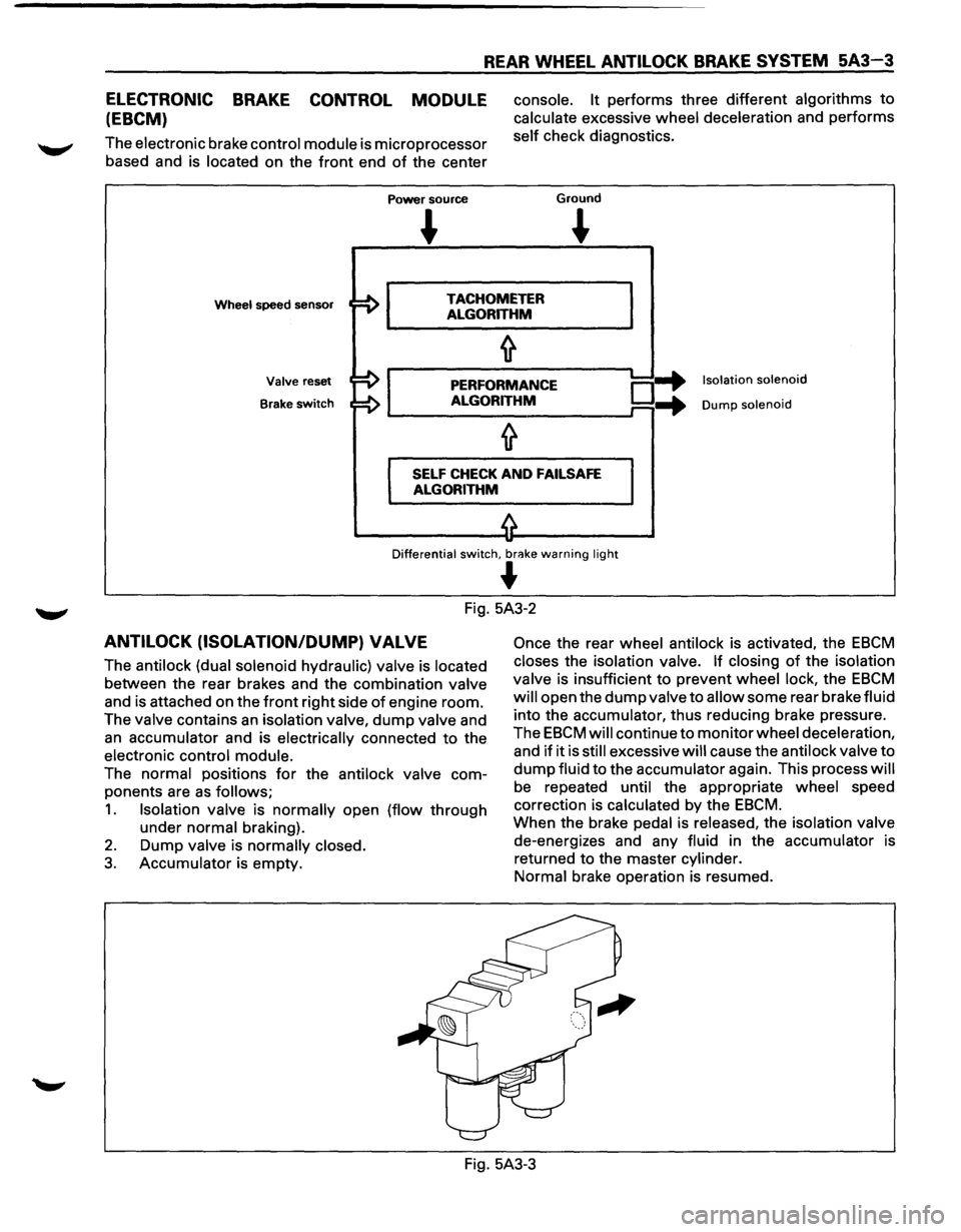
ELECTRONIC BRAKE CONTROL MODULE
(EBCM)
The electronic brake control module is microprocessor
based and is located on the
front end of the center
Power source
console. It performs three different algorithms to
calculate excessive wheel deceleration and performs
self check diagnostics.
Ground
~
Wheel speed sensor TACHOMETER
ALGORITHM
Valve reset
Brake
switch
PERFORMANCE
ALGORITHM o-+ ...
Isolation solenoid
Dump solenoid
SELF CHECK AND FAILSAFE
ALGORITHM
Differential switch, br<'!ke warning light
~
Fig. 5A3-2
ANTILOCK (ISOLATION/DUMP) VALVE
The antilock (dual solenoid hydraulic) valve is located
between the rear brakes and the combination valve
and is attached on the
front right side of engine room.
The valve contains
an isolation valve, dump valve and
an accumulator and is electrically connected to the
electronic control module.
The normal positions
for the antilock valve com
ponents are
as follows;
1. Isolation valve is normally open (flow through
under normal braking).
2. Dump valve is normally closed.
3. Accumulator is empty.
Once the rear wheel antilock is activated, the EBCM
closes the isolation valve. If closing of the isolation
valve is insufficient to prevent wheel lock, the
EBCM
will open the dump valve to allow some rear brake fluid
into the accumulator, thus reducing brake pressure.
The
EBCM will continue to monitor wheel deceleration,
and
if it is still excessive will cause the antilock valve to
dump fluid to the accumulator again. This process will
be repeated until the appropriate wheel speed
correction is calculated by the
EBCM.
When the brake pedal is released, the isolation valve
de-energizes and any fluid in the accumulator is
returned to the master cylinder.
Normal brake operation is resumed.
Fig. 5A3-3