differential ISUZU TROOPER 1995 Owner's Manual
[x] Cancel search | Manufacturer: ISUZU, Model Year: 1995, Model line: TROOPER, Model: ISUZU TROOPER 1995Pages: 1928
Page 270 of 1928
48 -28 REAR AXLE
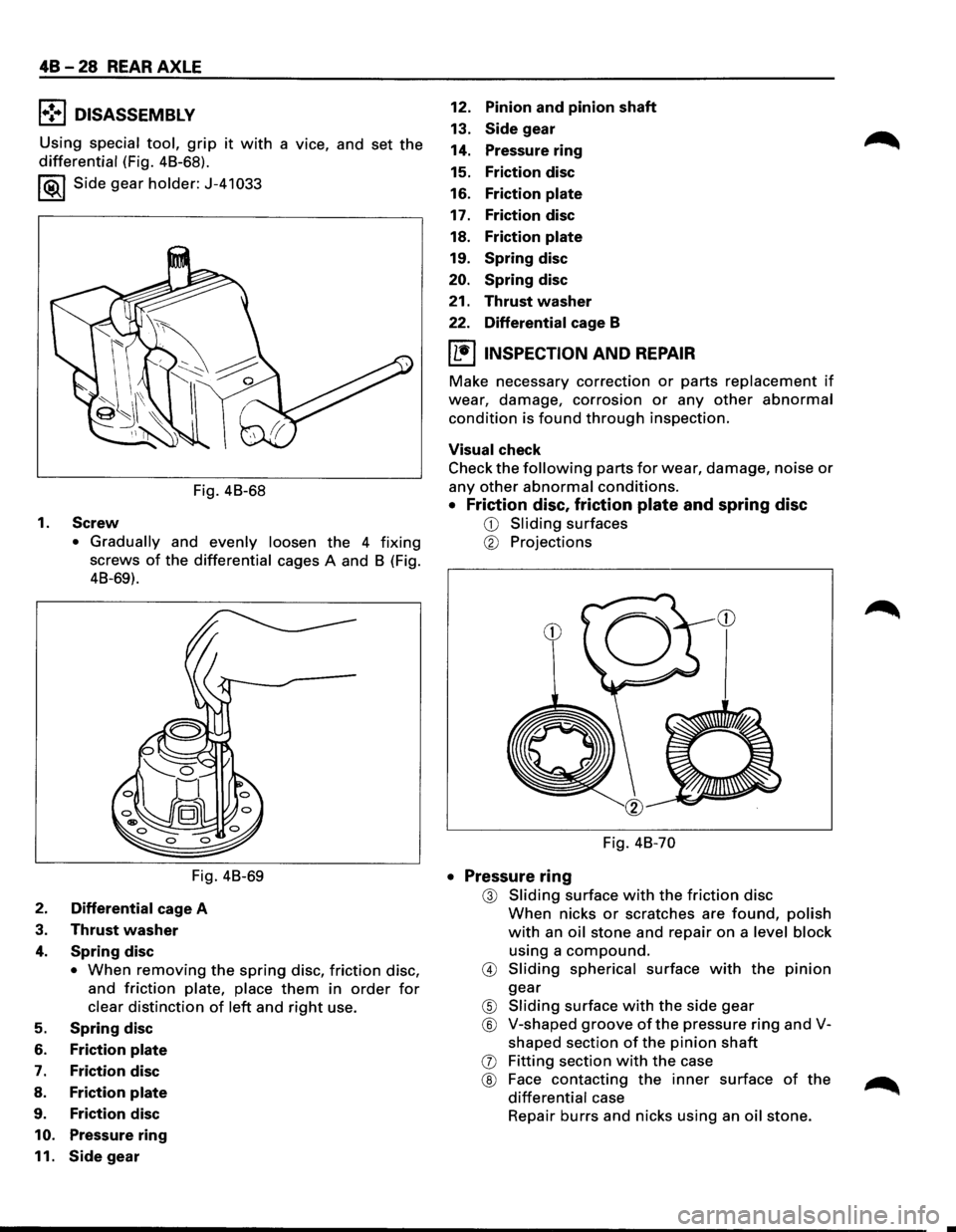
l•!-.1 DISASSEMBLY
Using special tool, grip it with a vice, and set the
differential (Fig. 48-68).
I ®.1 Side gear holder: J-41 033
Fig. 48-68
1.
Screw
• Gradually and evenly loosen the 4 fixing
screws of the differential cages A and 8 (Fig.
48-69).
Fig. 48-69
2. Differential cage A
3. Thrust washer
4. Spring disc
• When removing the spring disc, friction disc,
and
friction plate, place them in order for
clear distinction of left and right use.
5. Spring disc
6. Friction plate
7. Friction disc
8. Friction plate
9. Friction disc
10. Pressure ring
11. Side gear
12. Pinion and pinion shaft
13. Side gear
14. Pressure
ring
15. Friction disc
16. Friction plate
17. Friction disc
18.
Friction plate
19. Spring disc
20. Spring disc
21.
Thrust washer
22. Differential cage B
IL•IINSPECTION AND REPAIR
Make necessary correction or parts replacement if
wear, damage, corrosion or any other abnormal
condition is found through inspection.
Visual check
Check
the following parts for wear, damage, noise or
any other abnormal conditions.
• Friction disc, friction plate and spring disc
CD Sliding surfaces
® Projections
Fig. 48-70
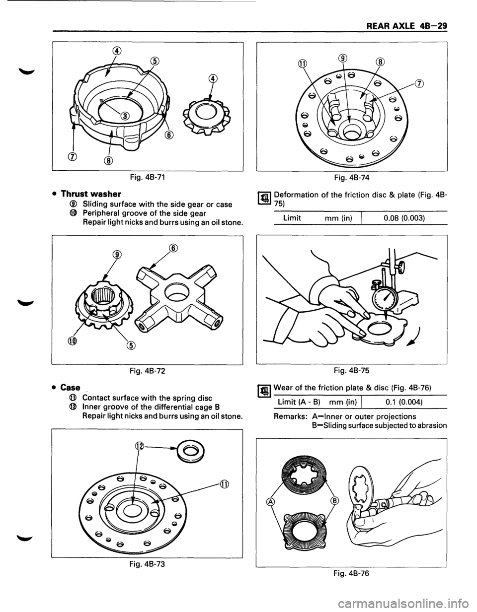
• Pressure ring
@ Sliding surface with the friction disc
When nicks or scratches are found, polish
with an oil stone and repair on a level block
using a
compound.
@ Sliding spherical surface with the pinion
gear
® Sliding surface with the side gear
® V-shaped groove of the pressure ring and V
shaped section
of the pinion shaft
(j) Fitting section with the case
® Face contacting the inner surface of the
differential case
Repair
burrs and nicks using an oil stone.
Page 271 of 1928
(j) @
Fig. 48-71
• Thrust washer
® Sliding surface with the side gear or case
@ Peripheral groove of the side gear
Repair
light nicks and burrs using an oil stone.
Fig. 48-72
• Case
G)) Contact surface with the spring disc
@ Inner groove of the differential cage B
Repair
light nicks and burrs using an oil stone.
1~
Fig. 48-73
REAR AXLE 48-29
Fig. 48-74
rfiil Deformation of the friction disc & plate (Fig. 48-
~75)
Limit mm (in) I 0.08 (0.003)
Fig. 48-75
1@1 Wear of the friction plate & disc (Fig. 48-76)
Limit (A -B) mm (in) I 0.1 (0.004)
Remarks:
A=lnner or outer projections
B=Siiding surface subjected to abrasion
Fig. 48-76
Page 272 of 1928
48-30 REAR AXLE
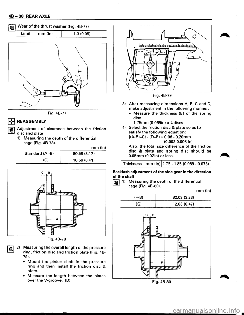
lfil!.l Wear of the thrust washer (Fig. 48-77)
Limit mm (in) I 1.3 (0.05)
Fig. 48-77
l•!•l REASSEMBLY
l"fll Adjustment of clearance between the friction
~ disc and plate
1) Measuring the depth of the differential
cage (Fig. 48-78).
~ 2)
mm(in)
Standard (A -8) 80.58 (3.17)
(C) 10.58 (0.41)
c 8
Fig. 48-78
Measuring the overall length ofthe pressure
ring,
friction disc and friction plate (Fig. 48-
79).
• Mount the pinion shaft in the pressure
ring and then install the friction disc &
plate.
•
Measure the length between the plates
over the V-groove. (D) Fig.
48-79
3) After measuring dimensions A, 8, C and D,
make adjustment in the following manner:
• Measure the thickness (E) of the spring
disc.
1.75mm (0.069in) x 4 discs
4) Select the friction disc & plate so as to
satisfy the following equation:
{(A-8)+C}-(D+E) = 0.06-0.20mm
(0.002-0.008 in)
Also, the total size difference of the friction
disc & plate and spring disc should be
0.05mm (0.02in) or less.
Thickness mm (in) 11.75-1.85 (0.069-0.073)
Backlash
adjustment of the side gear in the direction
of the shaft
lfil!.l1) Measuring the depth of the differential
cage (Fig. 48-80).
mm(in)
(F-8) 82.03 (3.23)
(G) 12.03 (0.47)
G 8
Fig. 48-80
Page 273 of 1928
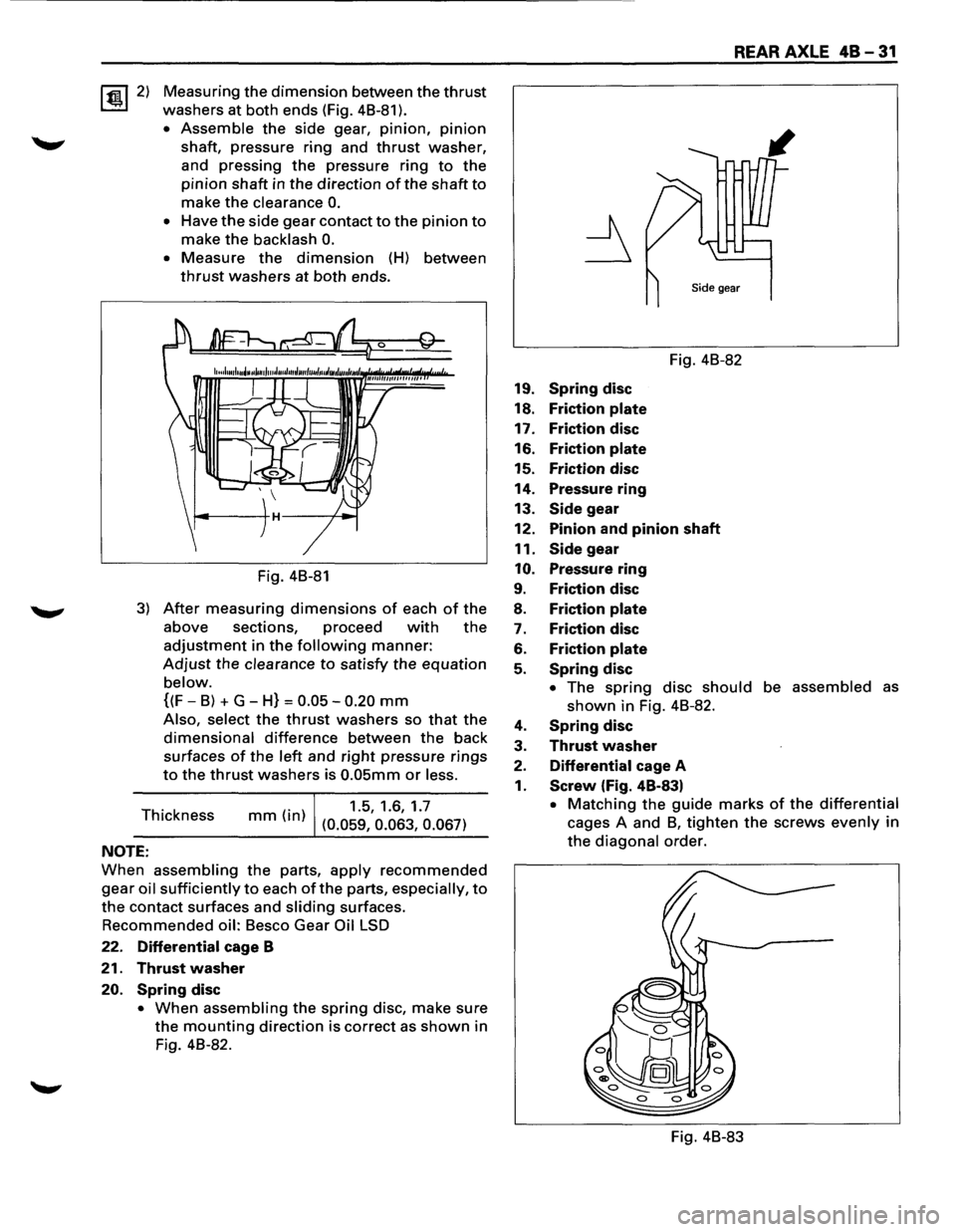
~2) Measuring the dimension between the thrust
washers at both ends (Fig. 48-81 ).
• Assemble the side gear, pinion, pinion
shaft, pressure ring and thrust washer,
and pressing
the pressure ring to the
pinion shaft in the direction of the shaft to
make the clearance 0.
• Have the side gear contact to the pinion to
make the backlash 0.
• Measure the dimension (H) between
thrust washers at both ends.
Fig. 48-81
3) After measuring dimensions of each of the
above sections, proceed with the
adjustment in the following manner:
Adjust the clearance to satisfy the equation
below.
{(F-8) + G-H} = 0.05-0.20 mm
Also, select the thrust washers so that the
dimensional difference between the back
surfaces
of the left and right pressure rings
to the thrust washers is 0.05mm or less.
Thickness (. )
1.5, 1.6, 1.7 mm In (0.059, 0.063, 0.067)
NOTE:
When assembling the parts, apply recommended
gear oil sufficiently to each of the parts, especially, to
the contact surfaces and sliding surfaces.
Recommended oil: 8esco Gear Oil LSD
22. Differential cage B
21. Thrust washer
20. Spring disc
• When assembling the spring disc, make sure
the mounting direction is correct as shown in
Fig. 48-82.
REAR AXLE 48-31
Fig. 48-82
19.
Spring disc
18. Friction plate
17. Friction disc
16. Friction plate
15. Friction disc
14. Pressure ring
13.
Side gear
12. Pinion and pinion shaft
11.
Side gear
10. Pressure ring
9. Friction disc
8. Friction plate
7. Friction disc
6. Friction plate
5. Spring disc
• The spring disc should be assembled as
shown in Fig. 48-82.
4. Spring disc
3. Thrust washer
2. Differential cage A
1. Screw (Fig. 48-83)
• Matching the guide marks of the differential
cages A and 8, tighten the screws evenly in
the diagonal order.
Fig. 48-83
Page 275 of 1928
REAR AXLE 48-33
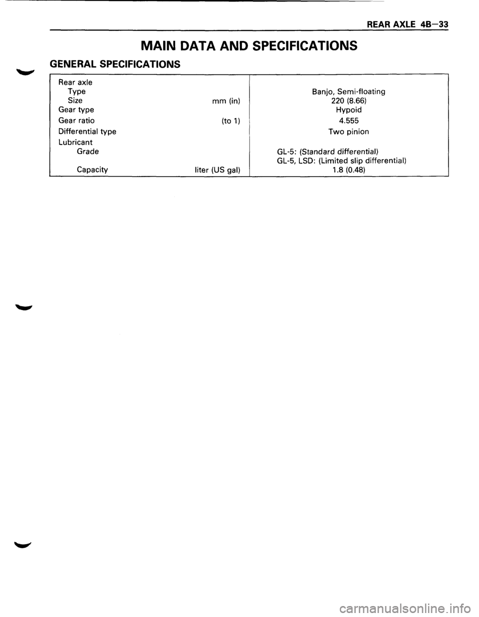
MAIN DATA AND SPECIFICATIONS
GENERAL SPECIFICATIONS
Rear axle
Type
Size
Gear type
Gear ratio
Differential type
Lubricant
Grade
Capacity
mm (in)
(to
1)
liter (US gal)
Banjo, Semi-floating
220 (8.66)
Hypoid
4.555
Two pinion
GL-5: (Standard
differential)
GL-5, LSD:
(Limited slip differential)
1.8 (0.48)
Page 276 of 1928
48 34 REAR AXLE
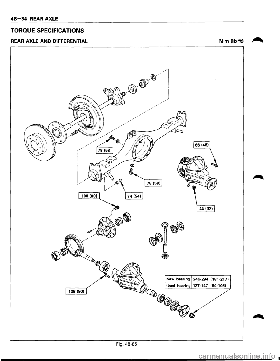
TORQUE SPECIFICATIONS
REAR AXLE AND DIFFERENTIAL
Fig. 48-85
N·m (lb·ft) ~
•
Page 277 of 1928
REAR AXLE 48-35
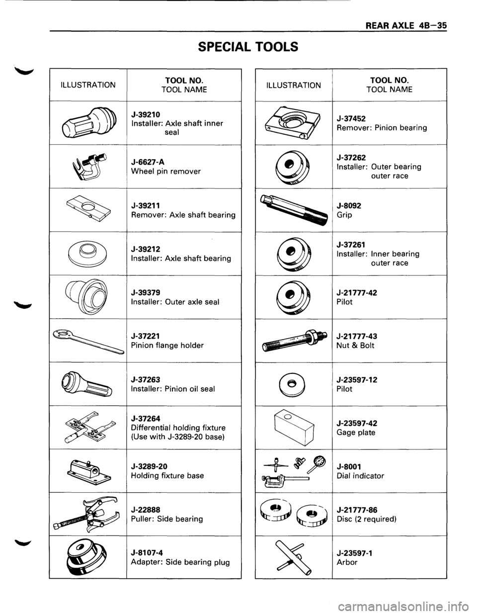
SPECIAL TOOLS
ILLUSTRATION TOOL NO.
TOOL NAME ILLUSTRATION TOOL NO.
TOOL NAME
~
J-39210
Installer: Axle shaft inner
seal @
J-37452
Remover: Pinion bearing
~
J-6627-A
Wheel pin remover @
J-37262
Installer: Outer bearing
outer race
~
J-39211
Remover: Axle shaft bearing
~
J-8092
Grip
®
J-39212
Installer: Axle shaft bearing @
J-37261
Installer: Inner bearing
outer race
~
J-39379
Installer: Outer axle seal @
J-21777-42
Pilot
~
J-37221
Pinion flange holder ~ ~
J-21777-43 -Nut & Bolt
~
J-37263
Installer: Pinion oil seal ®
J-23597-12
Pilot
~
J-37264
Differential holding fixture
(Use
with J-3289-20 base) ~
J-23597-42
Gage plate
~
J-3289-20
Holding fixture base +~~ J-8001
~I Dial indicator
a
~_j~
J-22888
Puller: Side bearing ~~
J-21777-86
Disc (2 required)
~
J-8107-4
Adapter: Side bearing plug
~
J-23597-1
Arbor
Page 279 of 1928
FRONT DRIVING AXLE 4C-1
SECTION 4C
FRONT DRIVING AXLE
'f CAUTION:
When fasteners are removed, always reinstall them at the same location from which they were removed.
If a fastener needs to be replaced, use the correct part number fastener for that application. If the correct
part
number fastener is not available, a fastener of equal size and strength (or stronger) may be used.
Fasteners
that are not reused, and those requiring thread locking compound, will be called out. The
correct
torque values must be used when installing fasteners that require torque. If the above conditions
are not followed, parts or system damage could result.
CONTENTS
General Description . . . . . . . . . . . . . . . . . . . . 4C-1
Diagnosis
of Front Driving Axle . . . . . . . . . . . 4C-2
Automatic Locking Free Wheel Hub . . . . . 4C-3
On-Vehicle Service ..................... 4C- 4
Pinion
Shaft Oil Seal Replacement . . . . . . 4C-4
Front Drive Shaft Joints Replacement . . . 4C-5
Front Hub Bearing Preload Check . . . . . . . 4C-5
Unit Repair . . . . . . . . . . . . . . . . . . . . . . . . . . . . 4C-6
Front Drive Axle Assembly . . . . . . . . . . . . 4C-6
Front Axle Drive Shaft . . . . . . . . . . . . . . . . 4C-9
Differential Assembly ................. 4C-14
Differential Cage Assembly . . . . . . . . . . . . 4C-24
Front Hub and Disc (4WD Model with
Automatic Locking Hub) . . . . . . . . . . . . 4C-28
Main Data and Specifications . . . . . . . . . . . . 4C-37
General Specifications . .
. . . . . . . . . . . . . . 4C-37
Torque Specifications ................. 4C-38
Special Tools .......................... 4C-41
GENERAL DESCRIPTION
This publication contains essential removal, instal
lation,
adjustment and maintenance procedures.
The
front axle utilizes a central disconnect type front
axle/transfer case system. The
drive axles are completely flexible assemblies,
consisting
of inner and outer constant velocity (CV)
drive shaft joints connected by an axle shaft. For
description
of front propeller shaft and universal
joint, refer to Section 4A "PROPELLER SHAFT".
Page 280 of 1928
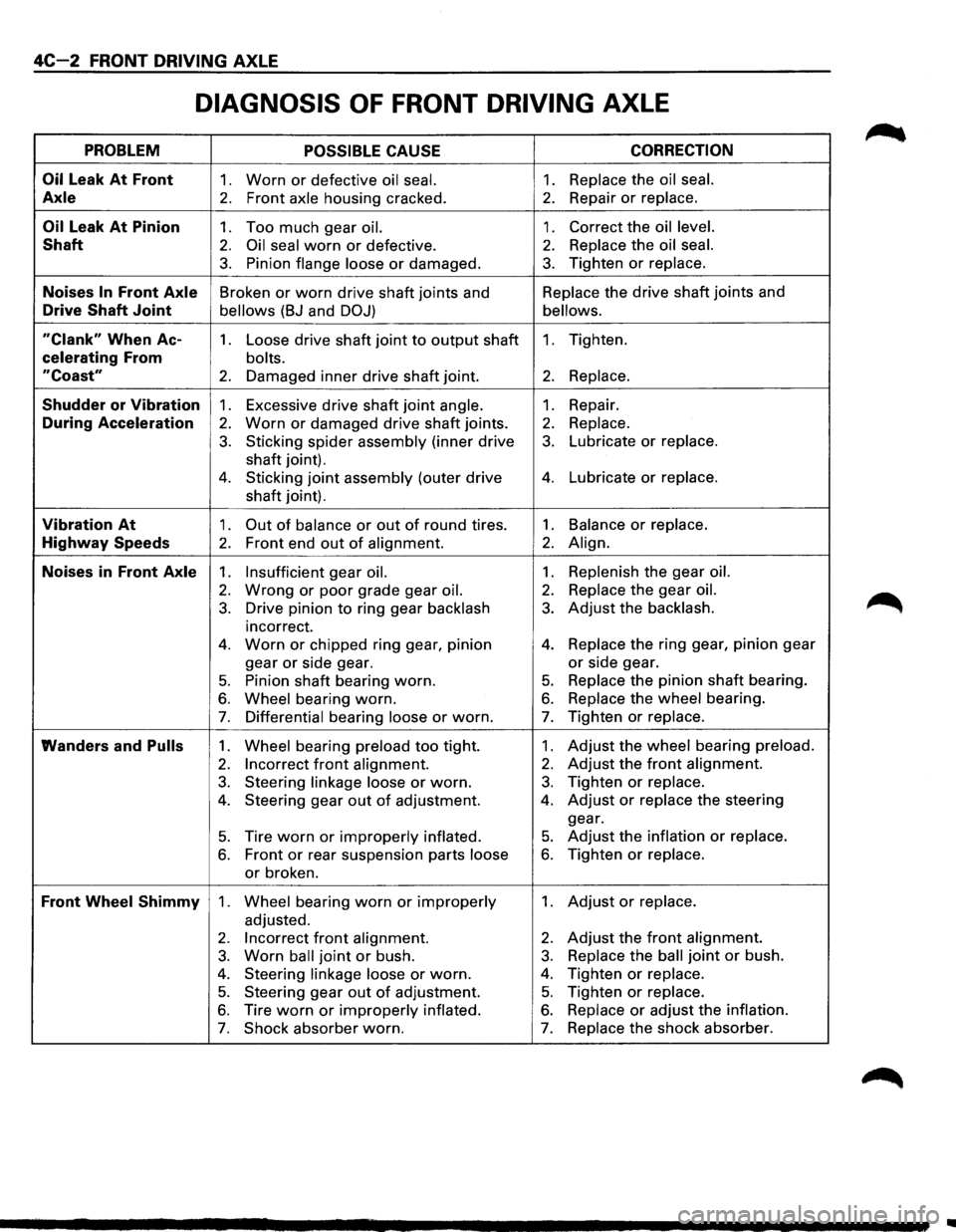
4C-2 FRONT DRIVING AXLE
DIAGNOSIS OF FRONT DRIVING AXLE
PROBLEM POSSIBLE CAUSE CORRECTION
Oil
Leak At Front 1. Worn or defective oil seal. 1. Replace the oil seal.
Axle 2. Front axle housing cracked. 2. Repair or replace.
Oil Leak At Pinion 1. Too much gear oil. 1. Correct the oil level.
Shaft 2. Oil seal worn or defective. 2. Replace the oil seal.
3. Pinion flange loose or damaged. 3. Tighten or replace.
Noises In Front Axle Broken or worn drive shaft joints and Replace
the drive shaft joints and
Drive Shaft Joint bellows (BJ and DOJ) bellows.
"Clank" When Ac-1. Loose drive shaft joint to output shaft 1. Tighten.
celerating From bolts.
"Coast" 2. Damaged inner drive shaft joint. 2. Replace.
Shudder or Vibration 1. Excessive drive shaft joint angle. 1. Repair.
During Acceleration 2. Worn or damaged drive shaft joints. 2. Replace.
3. Sticking spider assembly (inner drive 3. Lubricate or replace.
shaft joint).
4. Sticking joint assembly (outer drive 4. Lubricate or replace.
shaft joint).
Vibration At 1. Out of balance or out of round tires. 1. Balance or replace.
Highway Speeds 2. Front end out of alignment. 2. Align.
Noises in Front Axle 1. Insufficient gear oil. 1. Replenish the gear oil.
2. Wrong or poor grade gear oil. 2. Replace the gear oil.
3. Drive pinion to ring gear backlash 3. Adjust the backlash.
incorrect.
4. Worn or chipped ring gear, pinion 4. Replace the ring gear, pinion gear
gear
or side gear. or side gear.
5. Pinion shaft bearing worn. 5. Replace the pinion shaft bearing.
6. Wheel bearing worn. 6. Replace the wheel bearing.
7. Differential bearing loose or worn. 7. Tighten or replace.
Wanders and Pulls 1. Wheel bearing preload too tight. 1. Adjust the wheel bearing preload.
2. Incorrect front alignment. 2. Adjust the front alignment.
3. Steering linkage loose or worn. 3. Tighten or replace.
4. Steering gear out of adjustment. 4. Adjust or replace the steering
gear.
5. Tire worn or improperly inflated. 5. Adjust the inflation or replace.
6. Front or rear suspension parts loose 6. Tighten or replace.
or broken.
Front Wheel Shimmy 1. Wheel bearing worn or improperly 1. Adjust or replace.
adjusted.
2. Incorrect front alignment. 2. Adjust the front alignment.
3. Worn ball joint or bush. 3. Replace the ball joint or bush.
4. Steering linkage loose or worn. 4. Tighten or replace.
5. Steering gear out of adjustment. 5. Tighten or replace.
6. Tire worn or improperly inflated. 6. Replace or adjust the inflation.
7. Shock absorber worn. 7. Replace the shock absorber.
..
Page 283 of 1928
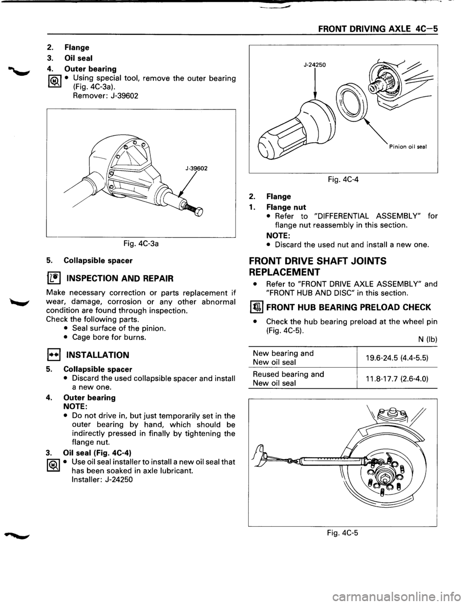
2. Flange
3. Oil seal
4. Outer bearing
f'Qil • Using special tool, remove the outer bearing
~ (Fig. 4C-3a).
Remover: J-39602
FRONT DRIVING AXLE 4C-5
Fig. 4C-4
2. Flange
1. Flange nut
• Refer to "DIFFERENTIAL ASSEMBLY" for
flange
nut reassembly in this section.
NOTE:
Fig. 4C-3a • Discard the used nut and install a new one.
5. Collapsible spacer
1L:~'I INSPECTION AND REPAIR
Make necessary correction or parts replacement if
wear, damage, corrosion or any other abnormal
condition are found through inspection.
Check the
following parts.
• Seal surface of the pinion.
• Cage bore for burns.
1••1 INSTALLATION
5. Collapsible spacer
• Discard the used collapsible spacer and install
a new one.
4. Outer bearing
NOTE:
• Do not drive in, but just temporarily set in the
outer bearing by hand, which should be
indirectly pressed in
finally by tightening the
flange nut.
3. Oil seal (Fig. 4C-4)
f'Qil • Use oil seal installer to install a new oil seal that
~ has been soaked in axle lubricant.
Installer: J-24250
FRONT DRIVE SHAFT JOINTS
REPLACEMENT
• Refer to "FRONT DRIVE AXLE ASSEMBLY" and
"FRONT HUB AND DISC" in this section.
~ FRONT HUB BEARING PRELOAD CHECK
• Check the hub bearing preload at the wheel pin
(Fig. 4C-5).
New bearing and
New oil seal
Reused bearing and
New
oil seal
Fig.
4C-5
N (lb)
19.6-24.5 (4.4-5.5)
11.8-17.7 (2.6-4.0)