differential ISUZU TROOPER 1995 Owner's Guide
[x] Cancel search | Manufacturer: ISUZU, Model Year: 1995, Model line: TROOPER, Model: ISUZU TROOPER 1995Pages: 1928
Page 285 of 1928
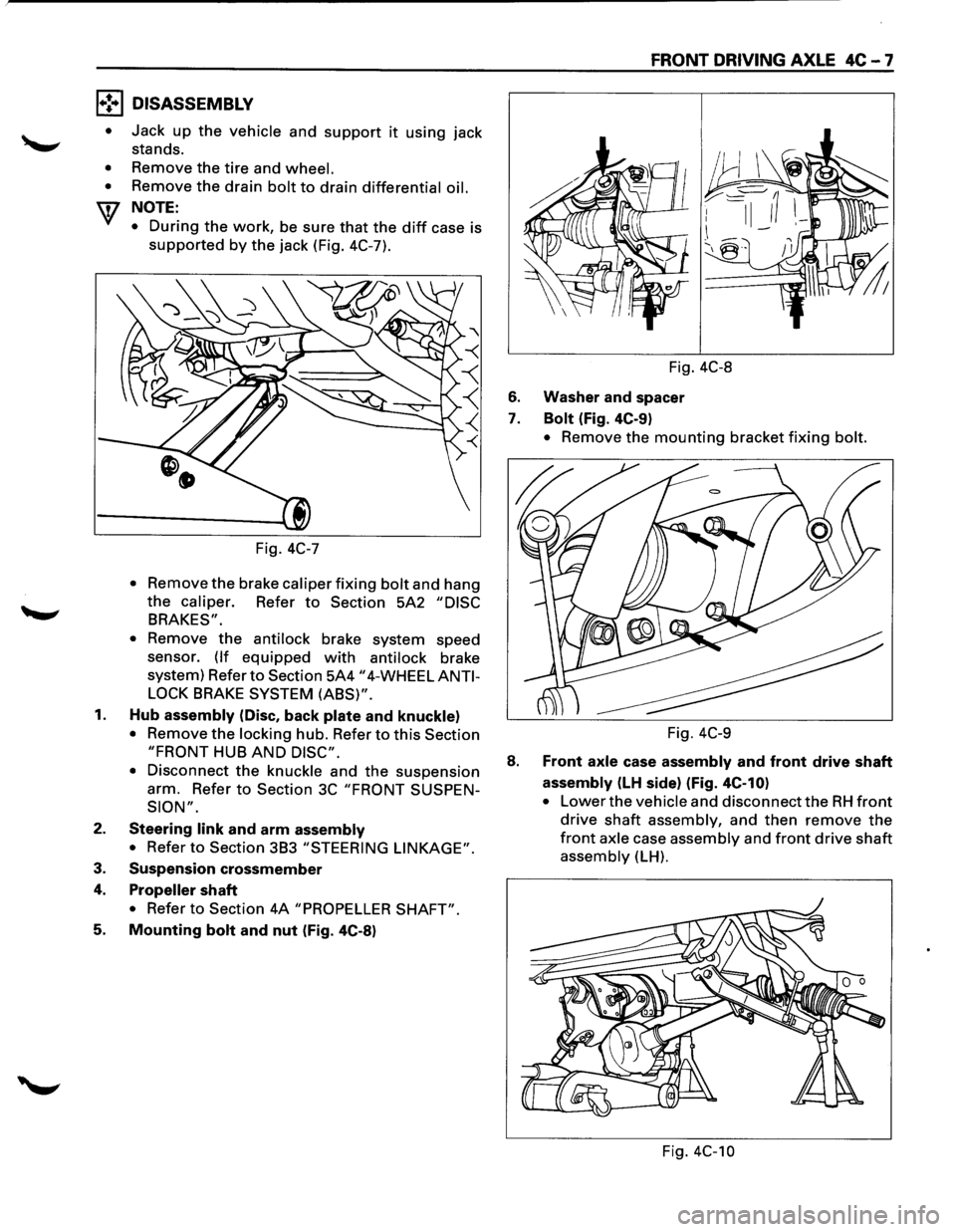
l•!•l DISASSEMBLY
•
•
•
Jack up the vehicle and support it using jack
stands.
Remove the
tire and wheel.
Remove the drain bolt to drain differential oil.
NOTE:
•
During the work, be sure that the diff case is
supported by the jack (Fig. 4C-7).
Fig.
4C-7
• Remov: the brake caliper fixing bolt and hang
the caliper. Refer to Section 5A2 "DISC
BRAKES".
•
Remove the antilock brake system speed
sensor.
(If equipped with antilock brake
system) Refer
to Section 5A4 "4-WHEEL ANTI
LOCK
BRAKE SYSTEM (ABS)".
1. Hub assembly (Disc, back plate and knuckle)
• Remove the locking hub. Refer to this Section
"FRONT HUB AND DISC".
•
Disconnect the knuckle and the suspension
arm. Refer
to Section 3C "FRONT SUSPEN
SION".
2. Steering link and arm assembly
• Refer to Section 3B3 "STEERING LINKAGE".
3. Suspension crossmember
4. Propeller shaft
• Refer to Section 4A "PROPELLER SHAFT".
5. Mounting bolt and nut (Fig. 4C-8)
FRONT DRIVING AXLE 4C-7
Fig. 4C-8
6. Washer and spacer
7. Bolt (Fig. 4C-9)
• Remove the mounting bracket fixing bolt.
Fig. 4C-9
8. Front axle case assembly and front drive shaft
assembly (LH side) (Fig. 4C-10)
• Lower the vehicle and disconnect the RH front
drive shaft assembly, and then remove the
front axle case assembly and front drive shaft
assembly (LH).
Fig. 4C-10
Page 287 of 1928
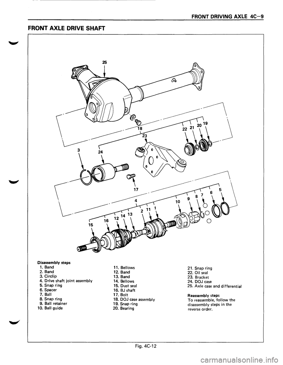
FRONT AXLE DRIVE SHAFT
Disassembly steps 1. Band
2. Band
3.
Circlip 4. Drive shaft joint assembly 5. Snap ring
6. Spacer
7.
Ball 8. Snap ring
9. Ball retainer
10. Ball guide 11.
Bellows 12.
Band
13. Band
14.
Bellows 15. Dust seal 16. BJ shaft
17. Bolt
18. DOJ case assembly 19. Snap ring
20. Bearing
Fig. 4C-12
FRONT DRIVING AXLE 4C-9
21. Snap ring
22. Oil seal 23. Bracket
24. DOJ case
25.
Axle case and differential
Reassembly
steps To reassemble, follow the disassembly steps in the reverse order.
Page 289 of 1928
__,.
9. Ball retainer
10. Ball guide
11. Bellows
12. Band
13. 14.
15.
16.
17.
18.
19.
20.
21.
22.
23.
24. 25.
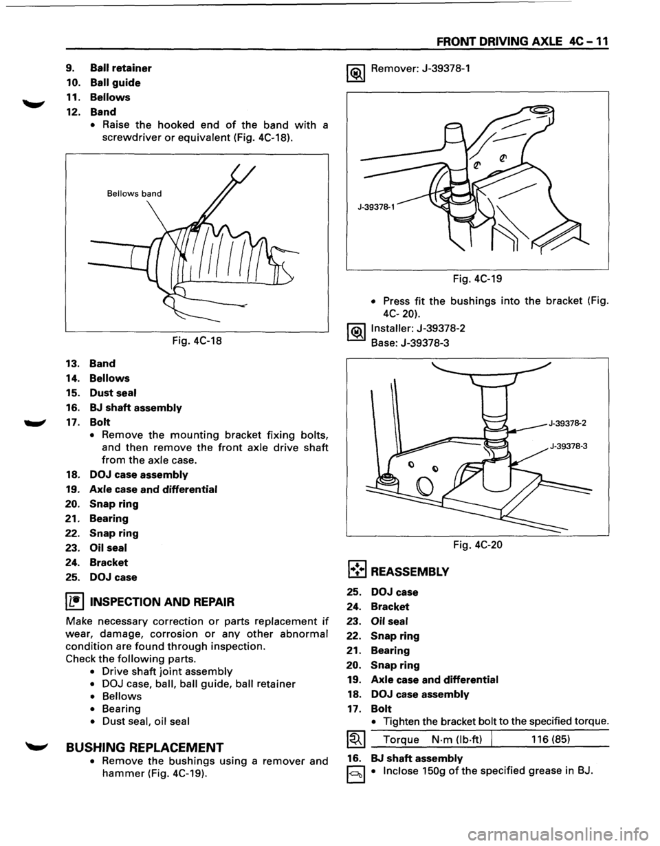
• Raise the hooked end of the band with a
screwdriver or equivalent (Fig. 4C-18).
Bellows band
Fig. 4C-18
Band
Bellows
Dust seal
BJ shaft assembly
Bolt
• Remove the mounting bracket fixing bolts,
and then remove the front axle drive shaft
from the axle case.
DOJ case assembly
Axle case and differential
Snap ring
Bearing
Snap ring
Oil seal
Bracket
DOJ case
I L•IINSPECTION AND REPAIR
Make necessary correction or parts replacement if
wear, damage, corrosion or any other abnormal
condition are found through inspection.
Check
the following parts.
• Drive shaft joint assembly
• DOJ
case, ball, ball guide, ball retainer
• Bellows
• Bearing
• Dust seal, oil seal
~ BUSHING REPLACEMENT
• Remove the bushings using a remover and
hammer (Fig. 4C-19).
FRONT DRIVING AXLE 4C -11
1 (ij),_j Remover: J-39378-1
Fig. 4C-19
• Press fit the bushings into the bracket (Fig.
4C-20).
j(ij),_jlnstaller:
J-39378-2
Base: J-39378-3
Fig.
4C-20
l•!•l REASSEMBLY
25. DOJ case
24. Bracket
23.
Oil seal
22. Snap ring
21.
Bearing
20.
Snap ring
19. Axle case and differential
18. DOJ case assembly
17. Bolt
• Tighten the bracket bolt to the specified torque.
~~~ Torque N-m (lb-ft) I 116 (85)
16. BJ
shaft assembly
1-c:::lcll • Inclose 150g ofthe specified grease in BJ.
Page 292 of 1928
4C-14 FRONT DRIVING AXLE
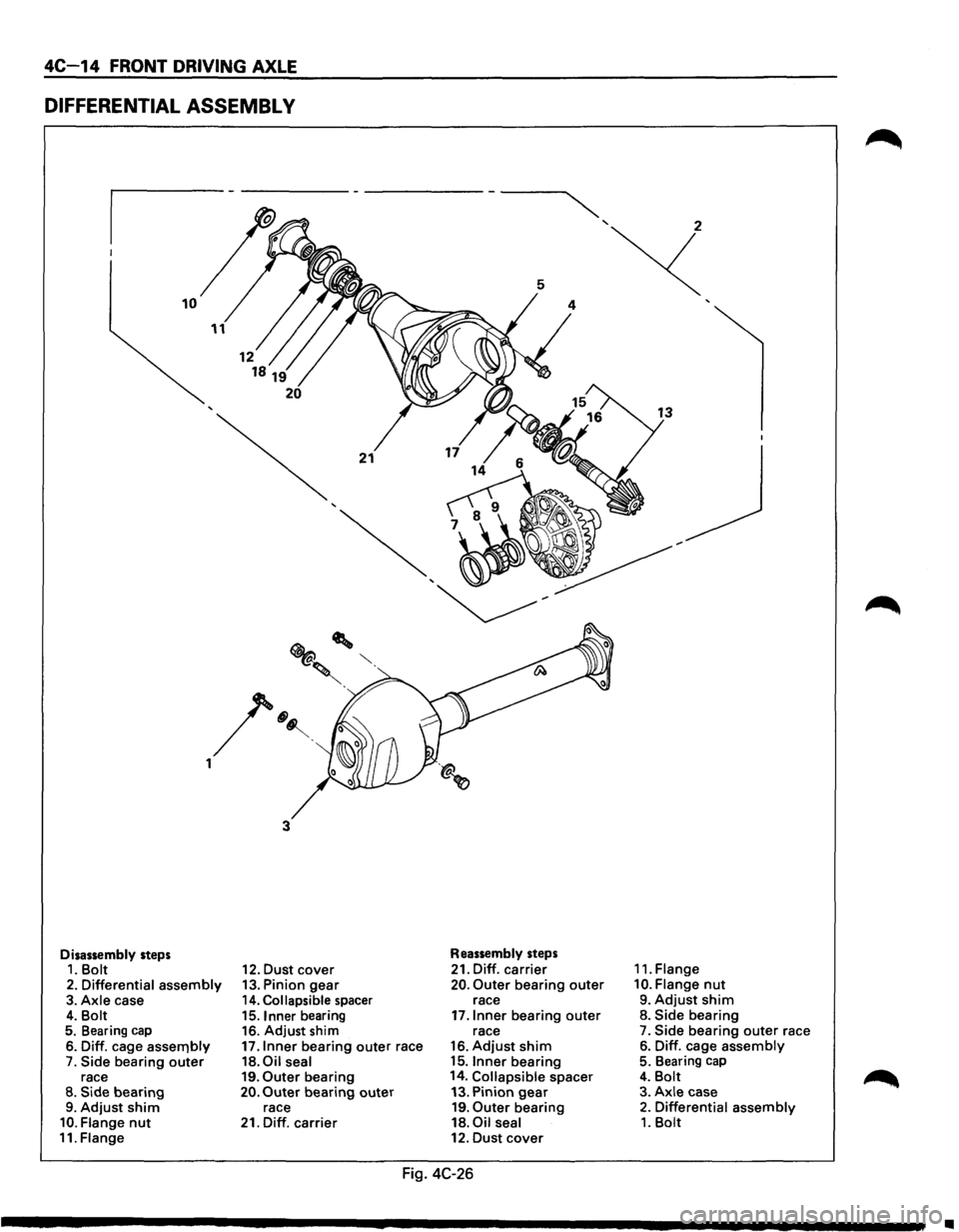
DIFFERENTIAL ASSEMBL V
Disassembly steps 1. Bolt
2. Differential assembly 3. Axle case 4. Bolt 5. Bearing cap
6. Diff. cage assernbly 7. Side bearing outer race 8. Side bearing 9. Adjust shim 10. Flange nut 11. Flange
3
12. Dust cover 13. Pinion gear 14. Collapsible spacer
15. Inner bearing
16. Adjust shim
17.1nner bearing outer race 18.0il seal 19. Outer bearing 20. Outer bearing outer race
21. Diff. carrier
Reassembly steps
21. Diff. carrier 20. Outer bearing outer race
17.1nner bearing outer race
16. Adjust shim 15.1nner bearing
14. Collapsible spacer
13. Pinion
gear 19. Outer bearing
18. Oil seal 12. Dust cover
Fig. 4C-26
11. Flange
10. Flange nut
9. Adjust shim 8. Side bearing 7. Side bearing outer race
6. Diff. cage assembly 5. Bearing cap
4. Bolt 3. Axle case 2. Differential assembly 1. Bolt
..
Page 293 of 1928
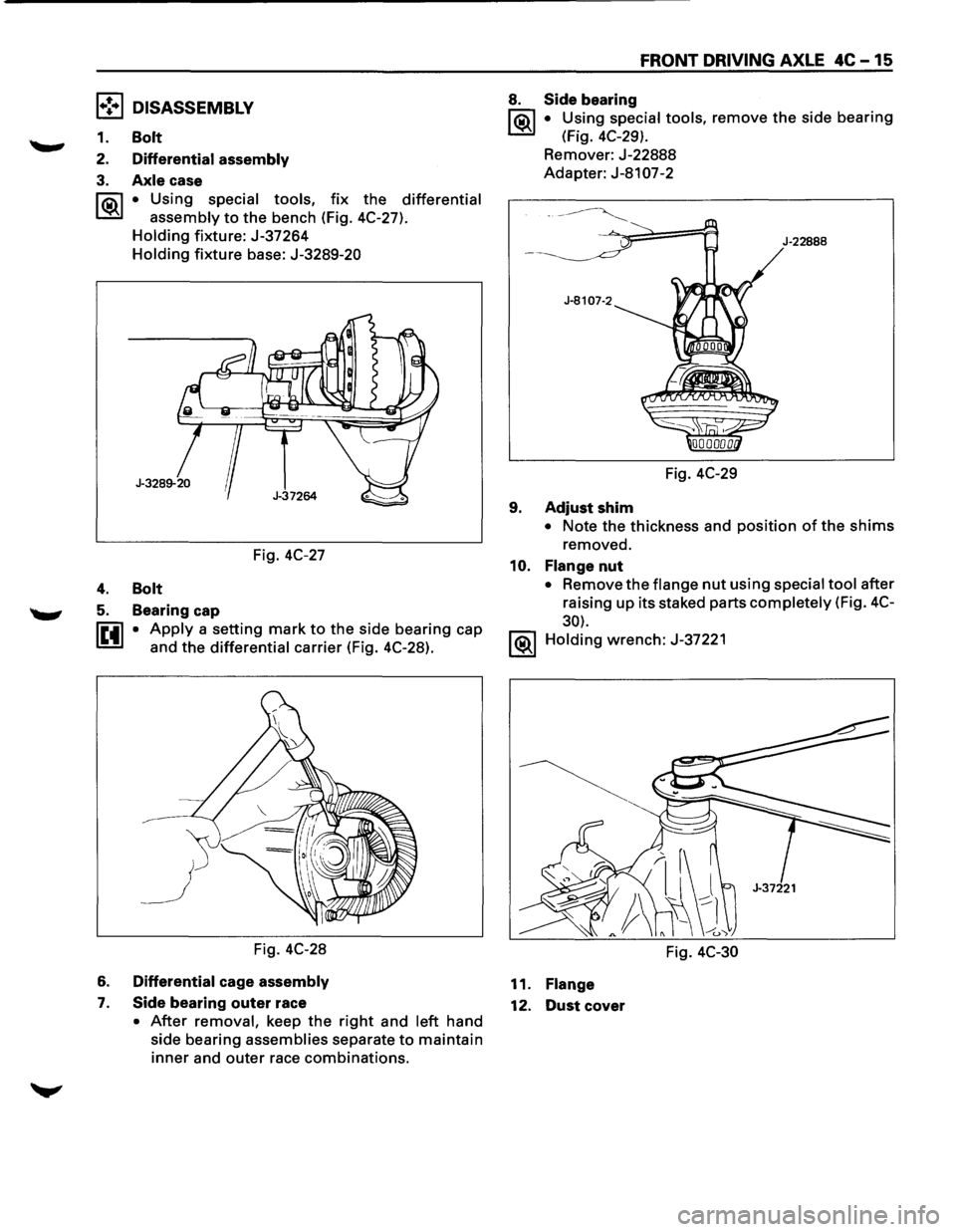
l•!•l DISASSEMBLY
1. Bolt
2. Differential assembly
3. Axle case
rr.i\1 • Using special tools, fix the differential
I.:Sil assembly to the bench (Fig. 4C-27).
Holding fixture: J-37264
Holding fixture base: J-3289-20
Fig.
4C-27
4. Bolt
5. Bearing cap
IE41 • Apply a setting mark to the side bearing cap
and
the differential carrier (Fig. 4C-28).
Fig.
4C-28
6. Differential cage assembly
7. Side bearing outer race
• After removal, keep the right and left hand
side bearing assemblies separate
to maintain
inner and outer race combinations.
FRONT DRIVING AXLE 4C-15
8. Side bearing
1®.1 • Using special tools, remove the side bearing
(Fig. 4C-29).
Remover: J-22888
Adapter: J-8107-2
Fig.
4C-29
9. Adjust shim
J-22888
• Note the thickness and position of the shims
removed.
10. Flange nut
• Remove the flange nut using special tool after
raising
up its staked parts completely (Fig. 4C-
30).
1®.1 Holding wrench: J-37221
Fig.
4C-30
11. Flange
12.
Dust cover
Page 294 of 1928
4C-16 FRONT DRIVING AXLE
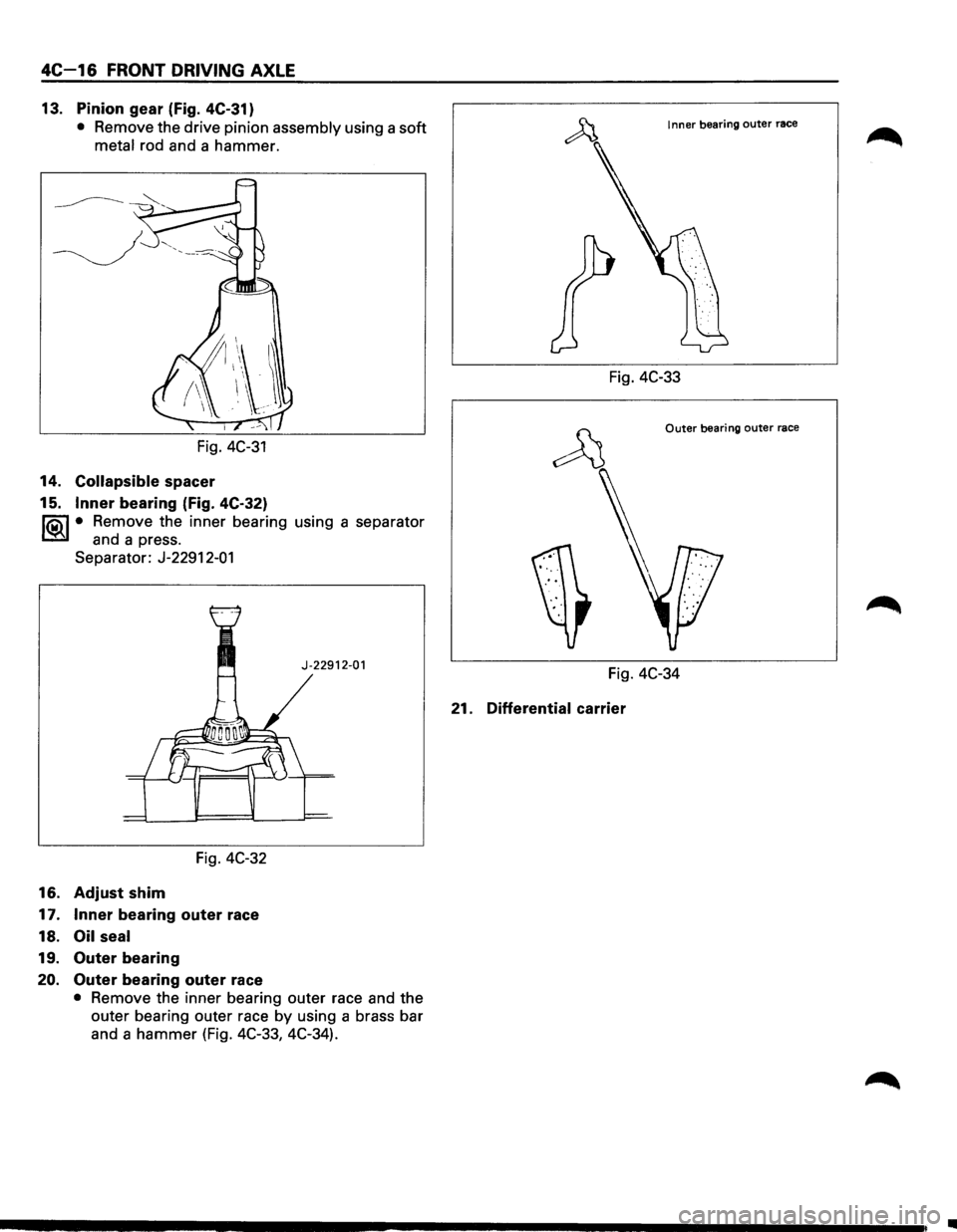
13. Pinion gear (Fig. 4C-31)
• Remove the drive pinion assembly using a soft
metal rod and a hammer.
Fig.
4C-31
14. Collapsible spacer
15.
Inner bearing (Fig. 4C-32)
li5\l • Remove the inner bearing using a separator
CSil and a press.
Separator: J-22912-01
J-22912-01
Fig. 4C-32
16. Adjust shim
17. Inner bearing outer race
18.
Oil seal
19. Outer bearing
20. Outer bearing outer race
• Remove the inner bearing outer race and the
outer bearing outer race
by using a brass bar
and a
hammer (Fig. 4C-33, 4C-34).
Inner bearing outer race
Fig. 4C-33
Outer bearing outer race
Fig. 4C-34
21. Differential carrier
•
Page 295 of 1928
l•!•l REASSEMBLY
21. Differential carrier
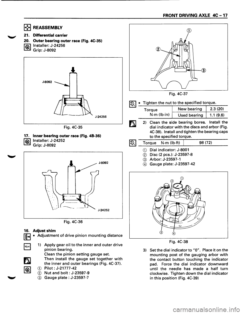
20. Outer bearing outer race (Fig. 4C-35)
l"ii\1 Installer: J-24256
~ Grip: J-8092
J-8092
J-24256
Fig. 4C-35
17. Inner bearing outer race (Fig. 48-36)
l®.llnstaller: J-24252
Grip:
J-8092
Fig. 4C-36
16. Adjust shim
I§FI • Adjustment of drive pinion mounting distance
B 1) Apply gear oil to the inner and outer drive
pinion bearing.
Clean
the pinion setting gauge set.
Then
install the gauge set together with
the inner and outer bearings (Fig. 4C-37).
CD Pilot: J-21777-42
® Nut and bolt: J-23597-9
® Gauge plate : J-23597 -7
FRONT DRIVING AXLE 4C -17
CD
Fig. 4C-37
~~I _• _T:.:i:?.g.:.:h.:.:te:.:..n:...:t:.:..:h~e...:.n.:..:u:..:.t,..:.to.::......:.:th..:...e:.....:.:sp:....e:....:c_if_ie_d_t_orr-=-q-ue_. __
Torque New bearing 2.3 (20)
N-m (lb-in)
Used bearing 1.1 (9.6)
2) Clean the side bearing bores. Install the
dial indicator with the discs and arbor (Fig.
4C-38).
Install and tighten the bearing caps
to the specified torque.
1.;-. I Torque N-m (lb·ft) J 98 (72) ~ ~~--~~.---------
CD Dial indicator: J-8001
® Disc (2 pes.): J-23597-8
® Arbor: J-23597-1
@ Gauge plate: J-23597-42
Fig. 4C-38
3) Set the dial indicator to "0". Place it on the
mounting post of the gauging arbor with
the contact button touching the indicator
pad. Force the dial indicator downward
until the needle has made a half turn
clockwise. Tighten down the dial indicator
in this position (Fig. 4C-39)
Page 297 of 1928
FRONT DRIVING AXLE 4C-19
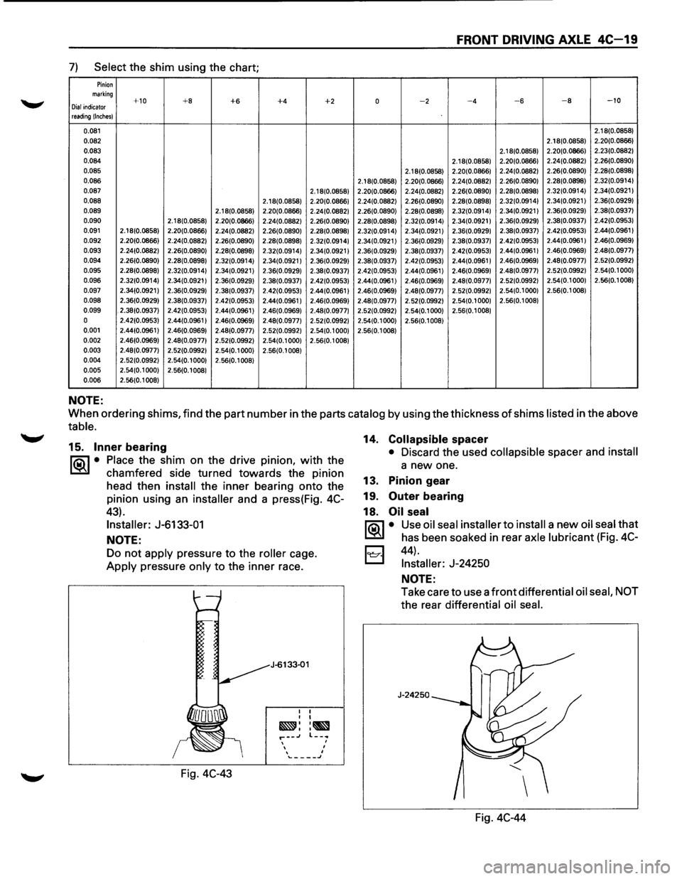
7) Select the shim using the chart;
Pinion marking +10 +8 +6 +4 +2 0 -2 -4 -6 -8 -10 Dial indicator reading !Inches)
0.081 2.18(0.0858)
0.082 2.18(0.0858) 2.20(0.0866)
0.083
2.1 8(0.0858) 2.20(0.0866)
2.23(0.0882)
0.084 2.1 8(0.0858) 2.20(0.0866) 2.24(0.0882) 2.26(0.0890)
0.085 2.18(0.0858) 2.20(0.0866) 2.24(0.0882)
2.26(0.0890) 2.28(0.0898)
0.086 2.18(0.0858) 2.20(0.0866) 2.24(0.0882)
2.26(0.0890) 2.28(0.0898) 2.32(0.0914)
0.087 2.18(0.0858) 2.20(0.0866)
2.24(0.0882) 2.26(0.0890) 2.28(0.0898) 2.32(0.0914) 2.34(0.0921) 0.088 2.18(0.0858) 2.20(0.0866) 2.24(0.0882) 2.26(0.0890) 2.28(0.0898) 2.32(0.0914) 2.34(0.0921) 2.36(0.0929) 0.089 2.18(0.0858) 2.20(0.0866) 2.24(0.0882) 2.26(0.0890)
2.28(0.0898) 2.32(0.0914) 2.34(0.0921) 2.36(0.0929) 2.38(0.0937)
0.090 2.18(0.0858) 2.20(0.0866) 2.24(0.0882) 2.26(0.0890) 2.28(0.0898) 2.32(0.0914) 2.34(0.0921) 2.36(0.0929)
2.38(0.0937)
2.42(0.0953)
0.091 2.18(0.0858)
2.20(0.0866) 2.24(0.0882) 2.26(0.0890) 2.28(0.0898) 2.32(0.0914) 2.34(0.0921) 2.36(0.0929) 2.38(0.0937) 2.42(0.0953) 2.44(0.0961
I
0.092 2.20(0.0866) 2.24(0.0882) 2.26(0.0890) 2.28(0.0898) 2.32(0.0914) 2.34(0.0921) 2.36(0.0929) 2.38(0.0937) 2.42(0.0953) 2.44(0.0961)
2.46(0.0969) 0.093 2.24(0.0882)
2.26(0.0890) 2.28(0.0898) 2.32(0.0914) 2.34(0.0921 I 2.36(0.0929) 2.38(0.0937) 2.42(0.0953) 2.44(0.0961 I 2.46(0.0969) 2.48(0.0977)
0.094 2.26(0.0890)
2.28(0.0898) 2.32(0.0914) 2.34(0.0921) 2.36(0.0929) 2.38(0.0937) 2.42(0.0953) 2.44(0.0961
I 2.46(0.0969) 2.48(0.0977) 2.52(0.0992)
0.095 2.28(0.0898) 2.32(0.0914)
2.34(0.0921 I 2.36(0.0929) 2.38(0.0937) 2.42(0.0953) 2.44(0.0961 I 2.46(0.0969) 2.48(0.0977) 2.52(0.0992) 2.54(0.1 000)
0.096 2.32(0.0914)
2.34(0.0921) 2.36(0.0929) 2.38(0.0937) 2.42(0.0953) 2.44(0.0961) 2.46(0.0969) 2.48(0.0977) 2.52(0.0992) 2.54(0.1000)
2.56(0.1
008)
0.097 2.34(0.0921) 2.36(0.0929)
2.38(0.0937) 2.42(0.0953) 2.44(0.0961 I 2.46(0.0969) 2.48(0.0977) 2.52(0.0992)
2.54(0.1 000) 2.56(0.1 008)
0.098 2.36(0.0929)
2.38(0.0937) 2.42(0.0953) 2.44(0.0961 I 2.46(0.0969) 2.48(0.0977)
2.52(0.0992) 2.54(0.1 000) 2.56(0.1 008)
0.099 . 2.38(0.0937) 2.42(0.0953) 2.44(0.0961) 2.46(0.0969)
2.48(0.0977) 2.52(0.0992)
2.54(0.1000) 2.56(0.1 008)
0 2.42(0.0953) 2.44(0.0961) 2.46(0.0969) 2.48(0.0977) 2.52(0.0992) 2.54(0.1 000) 2.56(0.1008)
0.001 2.44(0.0961)
2.46(0.0969) 2.48(0.0977) 2.52(0.0992) 2.54(0.1 000) 2.56(0.1008)
0.002 2.46(0.0969) 2.48(0.0977) 2.52(0.0992) 2.54(0.1 000) 2.56(0.1 008)
0.003 2.48(0.0977) 2.52(0.0992) 2.54(0.1 000) 2.56(0.1 008)
0.004 2.52(0.0992) 2.54(0.1 000) 2.56(0.1 008)
0.005 2.54(0.1 000) 2.56(0.1 008)
0.006 2.56(0.1 008)
NOTE:
When ordering shims, find the part number in the parts catalog by using the thickness of shims listed in the above
table.
15. Inner bearing
ria\~ • Place the shim on the drive pm1on, with the
~ chamfered side turned towards the pinion
head then
install the inner bearing onto the
pinion using an
installer and a press(Fig. 4C-
43).
Installer: J-6133-01
NOTE:
Do not apply pressure to the roller cage.
Apply pressure only to the inner race.
Fig.
4C-43
J-6133-01
I I I I
~::~ r--.J , I I '\...-___ J
14. Collapsible spacer
• Discard the used collapsible spacer and install
a new one.
13. Pinion gear
19.
Outer bearing
18.
Oil seal
ria\~ • Use oil seal installer to install a new oil seal that
~ has been soaked in rear axle lubricant (Fig. 4C-
I:;;:;I 44) .
t.::::::::.l Installer: J-24250
NOTE:
Take care to use a front differential oil seal, NOT
the rear differential oil seal.
J-24250
Fig. 4C-44
Page 298 of 1928
4C-20 FRONT DRIVING AXLE
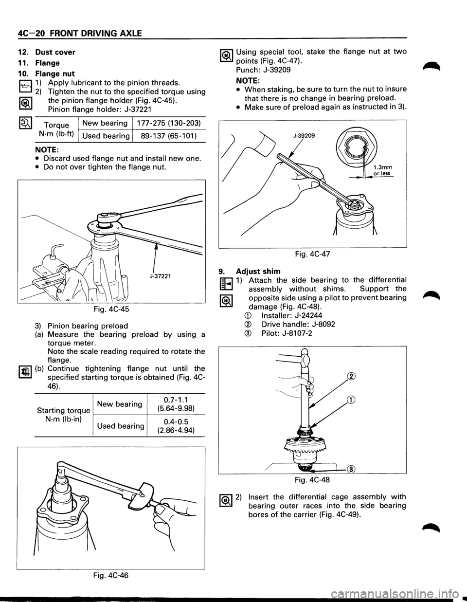
12. Dust cover
11.
Flange
1 0. Flange nut
8 1) Apply lubricant to the pinion threads.
2) Tighten the nut to the specified torque using
1®..1 the pinion flange holder (Fig. 4C-45).
Pinion
flange holder: J-37221
~~~ Torque New bearing 177-275 (130-203)
N·m (lb·ft)
Used bearing 89-137 (65-101)
NOTE:
• Discard used flange nut and install new one.
• Do not over tighten the flange nut.
Fig. 4C-45
3) Pinion bearing preload
(a) Measure the bearing preload by using a
torque meter.
Note the
scale reading required to rotate the
flange.
I~U (b) Continue tightening flange nut until the
specified starting torque is obtained (Fig. 4C-
46).
Newbearing 0 ·7
-1
·1
Starting
torque f---------+--(:_5_.6_4_-9_._98_:_)_
N·m (lb·in)
0.4-0.5
(2.86-4.94)
Used
bearing
Fig. 4C-46
I'Q\1 Using special tool, stake the flange nut at two
~ points (Fig. 4C-47).
Punch:
J-39209
NOTE:
• When staking, be sure to turn the nut to insure
that there is no change in bearing preload.
•
Make sure of preload again as instructed in 3).
Fig. 4C-47
1.3mm or less
9. Adjust shim
r;cJ 1) Attach the side bearing to the differential
~ assembly without shims. Support the
1®.1 opposite side using a pilot to prevent bearing
damage (Fig. 4C-48).
~ 2)
CD Installer: J-24244
® Drive handle: J-8092
@ Pilot: J-81 07-2
Fig. 4C-48
Insert the differential cage assembly with
bearing outer races into the side bearing
bores
of the carrier (Fig. 4C-49).
..
Page 300 of 1928
4C-22 FRONT DRIVING AXLE
7. Side bearing outer race
6. Differential cage assembly
5. Bearing cap
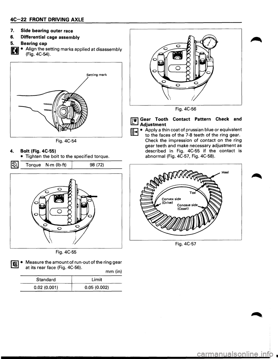
IP.il • Align the setting marks applied at disassembly
U (Fig. 4C-54).
Setting mark
Fig. 4C-54
4. Bolt (Fig. 4C-55)
• Tighten the bolt to the specified torque.
~~~ Torque N·m (lb·ft) 98 (72)
Fig. 4C-55
~·
Measure the amount of run-out of the ring gear
at its rear face (Fig. 4C-56).
mm (in)
Standard Limit
0.02
(0.001) 0.05 (0.002)
Fig. 4C-56
mil Gear Tooth Contact Pattern Check and
I.!:::..J Adjustment
r;o • Apply a thin coat of prussian blue or equivalent
ID to the faces of the 7-8 teeth of the ring gear.
Check the impression
of contact on the ring
gear teeth and make necessary adjustment
as
described in Fig. 4C-55 if the contact is
abnormal (Fig. 4C-57, Fig. 4C-58).
Fig. 4C-57
•