differential ISUZU TROOPER 1995 Repair Manual
[x] Cancel search | Manufacturer: ISUZU, Model Year: 1995, Model line: TROOPER, Model: ISUZU TROOPER 1995Pages: 1928
Page 372 of 1928
5A3-4 REAR WHEEL ANTILOCK BRAKE SYSTEM
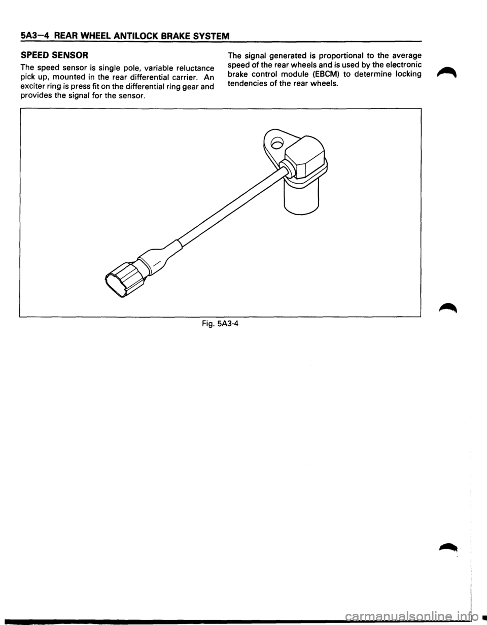
SPEED SENSOR
The speed sensor is single pole, variable reluctance
pick up, mounted
in the rear differential carrier. An
exciter ring
is press fit on the differential ring gear and
provides the signal for the sensor. The
signal generated is proportional
to the average
speed
of the rear wheels and is used by the electronic
brake control module
(EBCM) to determine locking
tendencies
of the rear wheels.
Fig. 5A3-4
•
Page 374 of 1928
5A3-6 REAR WHEEL ANTILOCK BRAKE SYSTEM
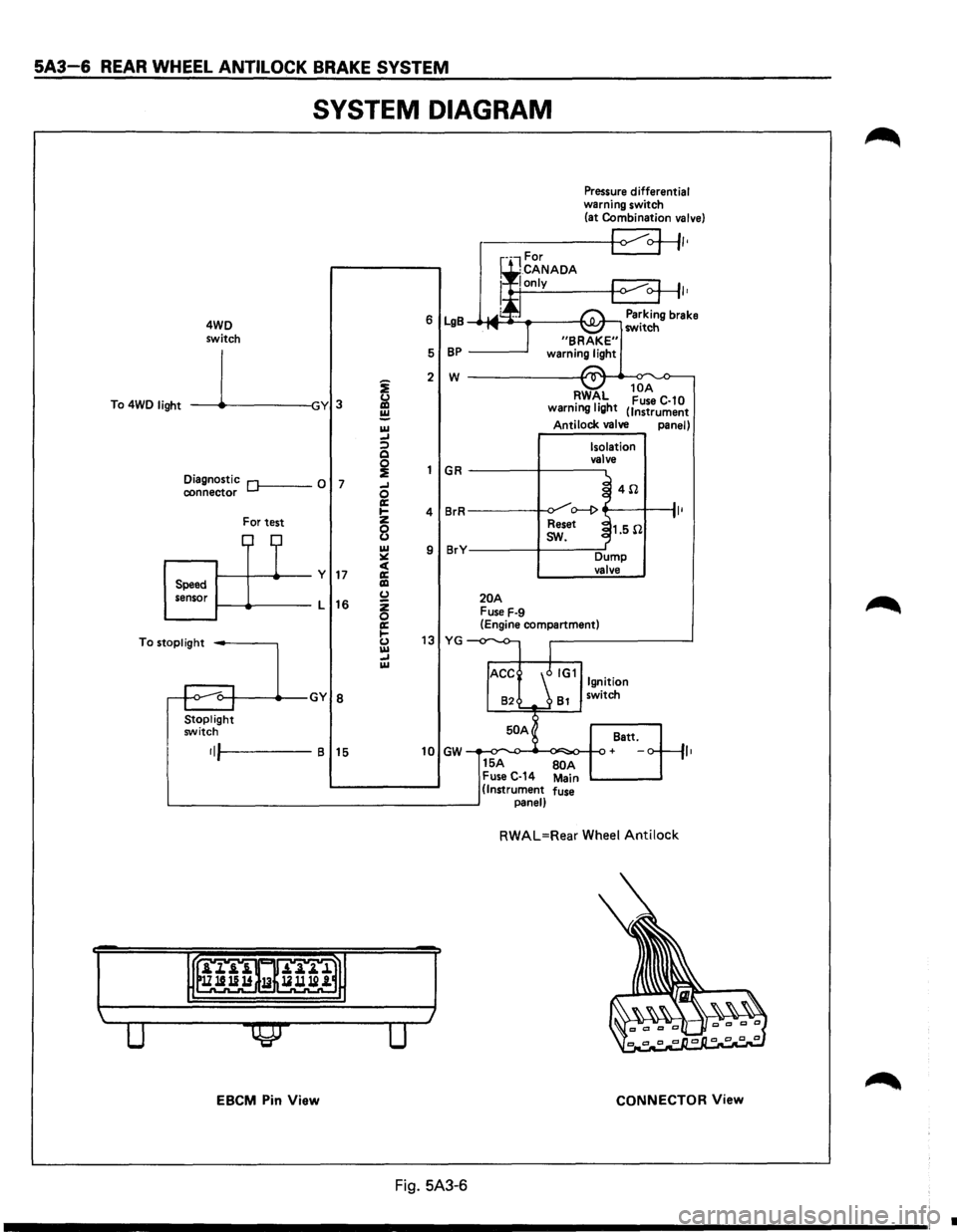
SYSTEM DIAGRAM
4WD
switch
To 4WD
light -----11~-----lGY 3
Diagnostic Of------0 7 connector
For test
1-----11---+--y 17 Speed
sensor 1-----lt-----L
16
To
stoplight -----,
Stoplight switch
•IJI-----B 15
EBCM Pin View
i
&l ~ IU _, :;) Q
~ _, 0 a: .... z
8 IU ~ c( a: liD (.) z 0 a: 1-(.) IU _, IU
Pressure differential warning switch
(at Combination valve)
r-----+-<1 ~+II•
I•
6 LgB Parking brake _.-MI ____ ___,I'\.JI.Jr-, switch
5
BP -----'
2 w ------------~~._~
GR
4 BrR
9 BrY
20A Fuse F-9
RWAL 10
A •
1• h Fuse C-10
warnmg IQ t (Instrument
Antilock valve panel)
Isolation
valve
~ 4il .J o--1> ~
Reset ~1.5il
I
sw.
Dump valve
(Engine compartment)
13 YG -
82 81 switch
50 A
Batt.
10 GW + ,,
15A BOA Fuse C-14 Main (Instrument fuse panel)
RWAL=Rear Wheel Antilock
CONNECTOR View
Fig. 5A3-6
•
Page 379 of 1928
REAR WHEEL ANTILOCK BRAKE SYSTEM 5A3-11
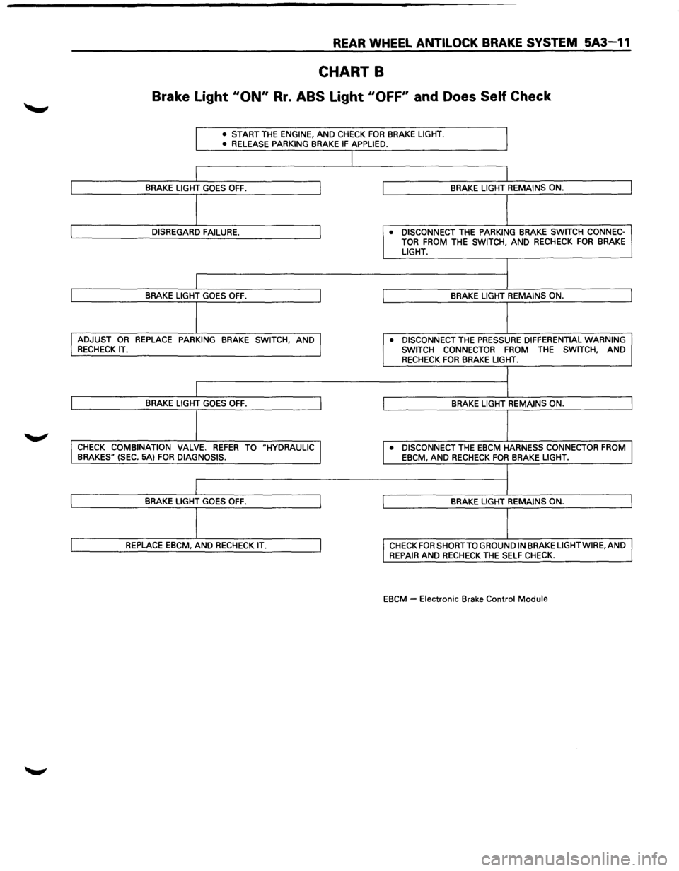
CHART B
Brake Light 110N" Rr. ABS Light "OFF' and Does Self Check
• START THE ENGINE, AND CHECK FOR BRAKE LIGHT.
• RELEASE PARKING BRAKE IF APPLIED.
J
I
I BRAKE LIGHT GOES OFF. J BRAKE LIGHT REMAINS ON.
I
I DISREGARD FAILURE. J • DISCONNECT THE PARKING BRAKE SWITCH CONNEC-
TOR FROM THE SWITCH, AND RECHECK FOR BRAKE LIGHT.
I
I
I BRAKE LIGHT GOES OFF. I BRAKE LIGHT REMAINS ON.
I I ADJUST OR REPLACE PARKING BRAKE SWITCH, AND J • DISCONNECT THE PRESSURE DIFFERENTIAL WARNING RECHECK IT.
SWITCH CONNECTOR
FROM THE SWITCH, AND RECHECK FOR BRAKE LIGHT.
I
I
I BRAKE LIGHT GOES OFF. I BRAKE LIGHT REMAINS ON.
j
I CHECK COMBINATION VALVE. REFER TO "HYDRAULIC I • DISCONNECT THE EBCM HARNESS CONNECTOR FROM
BRAKES" (SEC. 5A) FOR DIAGNOSIS.
EBCM, AND RECHECK FOR BRAKE LIGHT.
I
I
I BRAKE LIGHT GOES OFF. I BRAKE LIGHT REMAINS ON.
I
I REPLACE EBCM, AND RECHECK IT. I CHECK FOR SHORT TO GROUND IN BRAKE LIGHTWIRE,AND
REPAIR AND RECHECK THE SELF CHECK.
EBCM
= Electronic Brake Control Module
Page 393 of 1928
REAR WHEEL ANTILOCK BRAKE SYSTEM 5A3-25
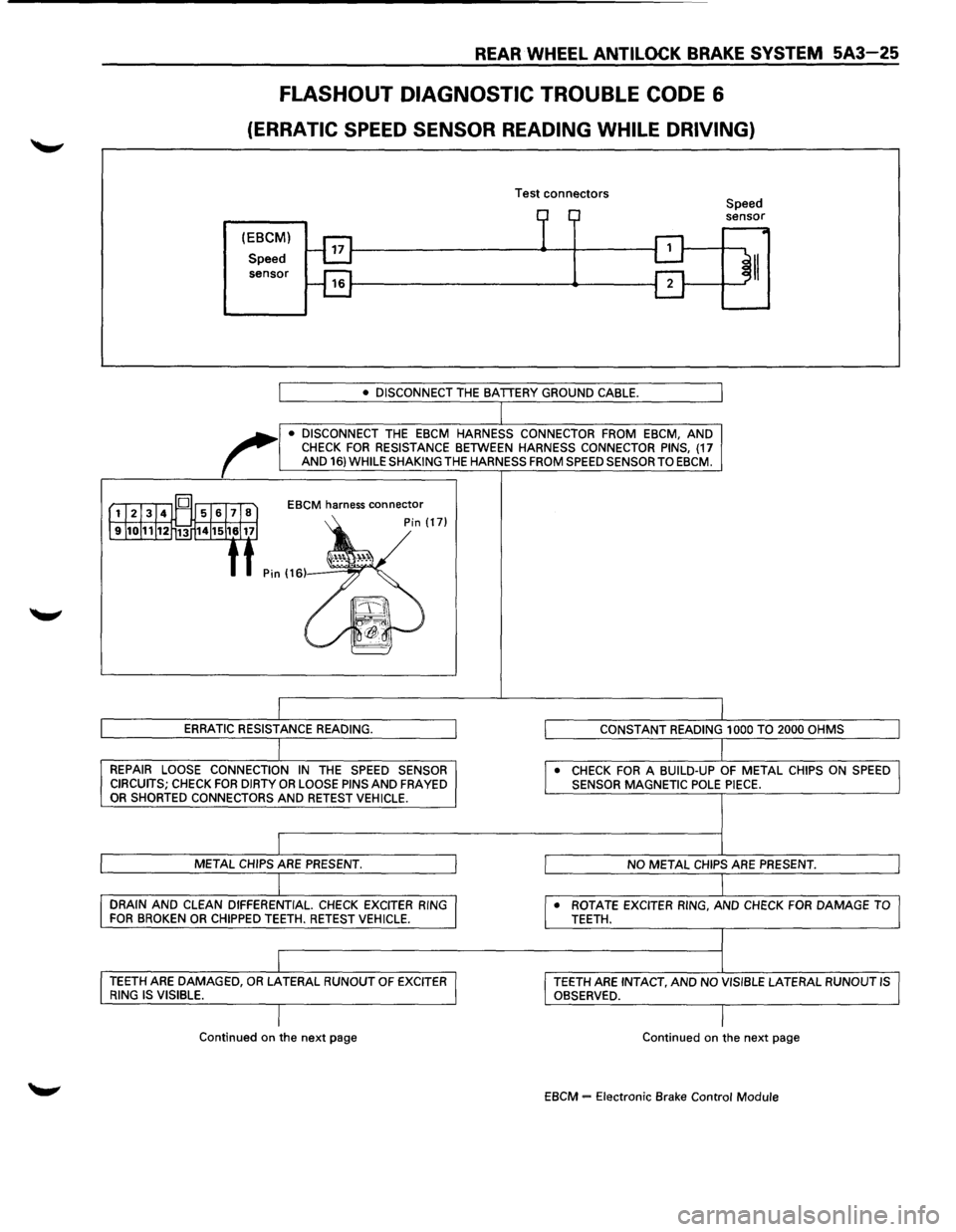
FLASHOUT DIAGNOSTIC TROUBLE CODE 6
(ERRATIC SPEED SENSOR READING WHILE DRIVING)
(EBCM)
Speed sensor
Test connectors Speed sensor
• DISCONNECT THE BATTERY GROUND CABLE.
• DISCONNECT THE EBCM HARNESS CONNECTOR FROM EBCM, AND
CHECK FOR RESISTANCE BETWEEN HARNESS CONNECTOR PINS, (17
AND 16) WHILE SHAKING THE HARNESS FROM SPEED SENSOR TO EBCM.
EBCM harness connector
Pin (17)
ERRATIC RESISTANCE READING.
REPAIR LOOSE CONNECTION
IN THE SPEED SENSOR
CIRCUITS; CHECK FOR DIRTY OR LOOSE PINS AND FRAYED OR SHORTED CONNECTORS AND RETEST VEHICLE.
METAL CHIPS ARE PRESENT.
DRAIN
AND CLEAN DIFFERENTIAL. CHECK EXCITER RING FOR BROKEN OR CHIPPED TEETH. RETEST VEHICLE.
TEETH ARE DAMAGED, OR LATERAL RUNOUT OF EXCITER
RING IS VISIBLE.
Continued on the next page
CONSTANT READING 1000 TO 2000 OHMS
•
CHECK FOR A BUILD-UP OF METAL CHIPS ON SPEED
SENSOR MAGNETIC POLE PIECE.
NO METAL CHIPS ARE PRESENT.
• ROTATE EXCITER RING,
AND CHECK FOR DAMAGE TO TEETH.
TEETH
ARE INTACT, AND NO VISIBLE LATERAL RUNOUT IS OBSERVED.
Continued on the next page
EBCM
= Electronic Brake Control Module
Page 644 of 1928
6C - 2 ENGINE FUEL
Fuel
Fuel
feed pipe return pipe Evapo pope
Fuel pressure
control valve Right
bank
Left bank Fuel tank
Canister
Throttle body Common chamber
Check & relief
valve
Vacuum Switch Valve canister
Fig.6C-1
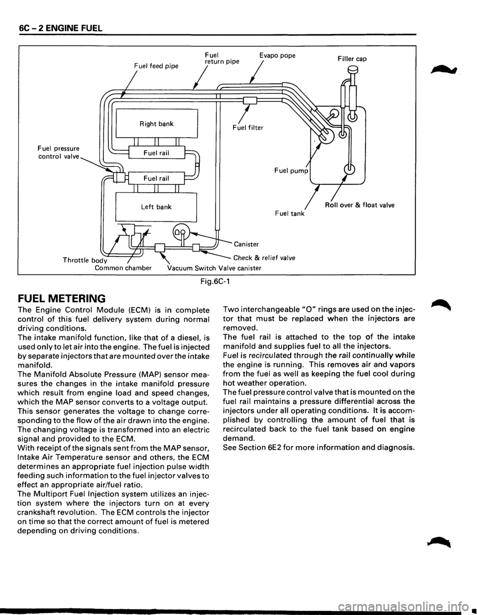
FUEL METERING
The Engine Control Module (ECM) 1s 1n complete
control of this fuel delivery system during normal
driving conditions.
The intake manifold function, like that of a diesel, is
used
only to let air into the engine. The fuel is injected
by separate injectors that are mounted over the intake
manifold.
The Manifold Absolute Pressure (MAP) sensor mea
sures
the changes in the intake manifold pressure
which result from engine load and speed changes,
which the MAP sensor converts to a voltage output.
This sensor generates the voltage to change corre
sponding to the flow ofthe air drawn into the engine.
The
changing voltage is transformed into an electric
signal and provided to the ECM.
With receipt of the signals sent from the MAP sensor,
Intake Air Temperature sensor and others, the ECM
determines an appropriate fuel injection pulse width
feeding such information to the fuel injector valves to
effect an appropriate air/fuel ratio.
The
Multipart Fuel Injection system utilizes an injec
tion system where the injectors turn on at every
crankshaft revolution. The ECM controls the injector
on time so that the correct amount of fuel is metered
depending on driving conditions.
Two interchangeable "0" rings are used on the injec
tor that must be replaced when the injectors are
removed.
The fuel rail is attached to the top of the intake
manifold and supplies fuel to all the injectors.
Fuel is recirculated
through the rail continually while
the engine is running. This removes air and vapors
from the fuel as well as keeping the fuel cool during
hot weather operation.
The fuel pressure control valve that is mounted on the
fuel rail maintains a pressure differential across the
injectors under all operating conditions. It is accom
plished by controlling the amount of fuel that is
recirculated back
to the fuel tank based on engine
demand.
See Section 6E2 for more information and diagnosis.
;au
•
Page 713 of 1928
DRIVEABILITY AND EMISSIONS 6E2-17
I OPERATING CONDITIONS READ I
I SYSTEMS CONTROLLED I
• Air Conditioning "On" or "Off" • Evaporative Emission Canister
• Engine Coolant Temperature Purge
• Crankshaft Position • Exhaust Gas Recirculation
• Exhaust Heated Oxygen Sensor • Ignition Control
• Electronic Ignition Reference • Fuel Control
• Crankshaft Position
ENGINE • Idle Air Control
• Engine Speed (RPM} CONTROL • Electric Fuel Pump
• Manifold Absolute Pressure (MAP)
MODULE • Air Conditioning
• Battery Positive Voltage (ECM) • Diagnostics
• Throttle Position Sensor • Malfunction Indicator Lamp
• Vehicle Speed Sensor • Diagnostic Test Terminal
• Fuel Pump Voltage • Data Output
• Power Steering Pressure • Transmission Control Module
• Intake Air Temperature • Knock Sensor (DOHC)
• Differential Pressure • Induction Air Control Plate System
• Knock Sensor (DOHC)
(DOHC)
• Exhaust Gas Recirculation Vacuum
• Air Conditioning High Side Pressure
Fig. 6E2-3
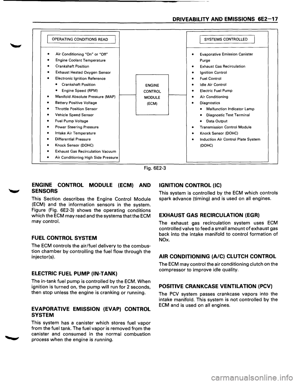
ENGINE CONTROL MODULE (ECM) AND
SENSORS
This Section describes the Engine Control Module
(ECM) and the information sensors in the system.
Figure (Fig. 6E2-3) shows the operating conditions
which the
ECM may read and the systems thatthe ECM
may control.
FUEL CONTROL SYSTEM
The ECM controls the air/fuel delivery to the combus
tion chamber by
controlling the fuel flow through the
injector(s).
ELECTRIC FUEL PUMP (IN-TANK)
The in-tank fuel pump is controlled by the ECM. When
ignition is turned on, the
pump will run for 2 seconds,
then stop
unless the engine is cranking or running.
EVAPORATIVE EMISSION (EVAP) CONTROL
SYSTEM
This system has a canister which stores fuel vapor
from the fuel tank. The fuel vapor is removed from the
canister and consumed in the
normal combustion
process when the engine
is running.
IGNITION CONTROL (IC)
This system is controlled by the ECM which controls
spark advance (timing) and is used on all engines.
EXHAUST GAS RECIRCULATION (EGR)
The exhaust gas recirculation system uses ECM
controlled valve to feed a small amount of exhaust gas
back into the intake
manifold to control formation of
NOx.
AIR CONDITIONING (A/C) CLUTCH CONTROL
The ECM may control the air conditioning clutch on the
compressor
to improve idle quality.
POSITIVE CRANKCASE VENTILATION (PCV)
The PCV system passes crankcase vapors into the
intake
manifold. This system is not controlled by the
ECM and is used on all engines.
Page 815 of 1928
FUEL INJECTORS
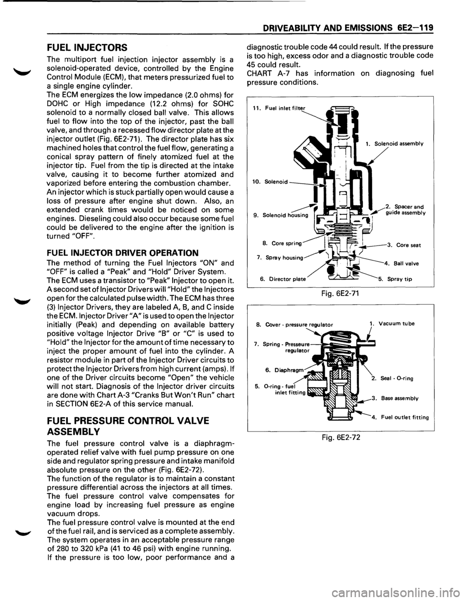
The multipart fuel injection injector assembly is a
solenoid-operated device, controlled
by the Engine
Control Module (ECM), that meters pressurized fuel to
a single engine cylinder.
The
ECM energizes the low impedance (2.0 ohms) for
DOHC or High impedance (12.2 ohms) for SOHC
solenoid to a normally closed ball valve. This allows
fuel
to flow into the top of the injector, past the ball
valve, and through a recessed
flow director plate at the
injector outlet (Fig. 6E2-71). The director plate has six
machined holes
that control the fuel flow, generating a
conical spray pattern
of finely atomized fuel at the
injector tip. Fuel
from the tip is directed at the intake
valve, causing
it to become further atomized and
vaporized before entering the combustion chamber.
An injector which is stuck partially open
would cause a
loss
of pressure after engine shut down. Also, an
extended crank times would be noticed on some
engines. Dieseling could also
occ!Jr because some fuel
could be delivered
to the engine after the ignition is
turned
"OFF".
FUEL INJECTOR DRIVER OPERATION
The method of turning the Fuel Injectors "ON" and
"OFF" is called a "Peak" and "Hold" Driver System.
The
ECM uses a transistor to "Peak" Injector to open it.
A second set
of Injector Drivers will "Hold" the Injectors
open for the calculated pulse width. The ECM has three
(3) Injector Drivers, they are labeled A, 8, and C inside
the
ECM. Injector Driver "A" is used to open the Injector
initially (Peak) and depending on available battery
positive voltage
Injector Drive "8" or "C" is used to
"Hold" the Injector for the amount of time necessary to
inject the proper amount of fuel into the cylinder. A
resistor module in part
of the Injector Driver circuits to
protect the Injector Drivers from high current (amps). If
one of the Driver circuits become "Open" the vehicle
will
not start. Diagnosis of the Injector driver circuits
are done
with Chart A-3 "Cranks But Won't Run" chart
in
SECTION 6E2-A of this service manual.
FUEL PRESSURE CONTROL VALVE
ASSEMBLY
The fuel pressure control valve is a diaphragm
operated relief valve
with fuel pump pressure on one
side and regulator spring pressure and intake manifold
absolute pressure on the other (Fig. 6E2-72).
The function
of the regulator is to maintain a constant
pressure differential across the injectors at all times.
The fuel pressure control valve compensates
for
engine load by increasing fuel pressure as engine
vacuum drops.
The fuel pressure control valve is mounted at the end
ofthe fuel rail, and is serviced as a complete assembly.
The system operates in
an acceptable pressure range
of 280 to 320 kPa (41 to 46 psi) with engine running.
If the pressure is too low, poor performance and a
DRIVEABILITV AND EMISSIONS 6E2-119
diagnostic trouble code 44 could result. If the pressure
is too high, excess odor and a diagnostic trouble code
45 could result.
CHART A-7 has information on diagnosing fuel
pressure conditions.
11. Fuel inlet
Fig. 6E2-71
1. Solenoid assembly
Spacer
and
guide assembly
. Ball valve
8. Cover-pressure regulator 1. Vacuum tube
7.
6.
Seal · 0-ring
Base assembly
Fuel
outlet fitting
Fig. 6E2-72
Page 1214 of 1928
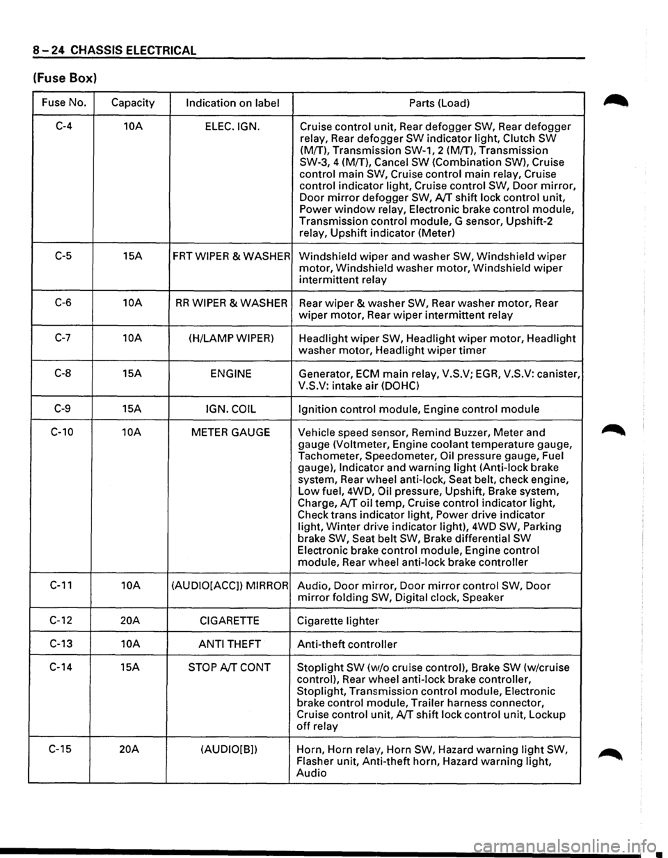
8-24 CHASSIS ELECTRICAL
(Fuse Box)
Fuse No.
Capacity Indication on label Parts (Load)
C-4 10A
ELEC.IGN. Cruise control unit, Rear defogger SW, Rear defogger
relay, Rear
defo9ger SW indicator light, Clutch SW
(M{T), Transmission SW-1, 2 (M!T), Transmission
SW-3, 4 (M{T), Cancel
SW (Combination SW), Cruise
control main
SW, Cruise control main relay, Cruise
control indicator light, Cruise control
SW, Door mirror,
Door mirror defogger SW, AfT shift lock control unit,
Power window relay, Electronic brake control module,
Transmission control module, G sensor, Upshift-2
relay, Upshift indicator (Meter)
C-5 15A FRTWIPER &WASHER
Windshield wipt~r and washer SW, Windshield wiper
motor, Windshit~ld washer motor, Windshield wiper
intermittent relay
C-6 10A RR WIPER & WASHER
Rear wiper & washer SW, Rear washer motor, Rear
wiper motor, Rear wiper intermittent relay
C-7 10A (H/LAMP WIPER) Headlight wiper SW, Headlight wiper motor, Headlight
washer motor, Headlight
wiper timer
C-8 15A ENGINE Generator, ECM main relay, V.S.V; EGA, V.S.V: canister,
V.S.V: intake air
(DOHC)
C-9 15A IGN. COIL Ignition control module, Engine control module
C-10 10A METER GAUGE Vehicle speed stmsor, Remind Buzzer, Meter and
gauge
(Voltmeter, Engine coolant temperature gauge,
Tachometer, Speedometer,
Oil pressure gauge, Fuel
gauge),
Indicator and warning light (Anti-lock brake
system, Rear wheel anti-lock, Seat belt, check engine,
Low fuel, 4WD,
Oil pressure, Upshift, Brake system,
Charge,
AfT oil temp, Cruise control indicator light,
Check trans indicator light,
Power drive indicator
light,
Winter drive indicator light), 4WD SW, Parking
brake SW, Seat belt SW, Brake differential SW
Electronic brake control module, Engine control
module, Rear wheel anti-lock brake controller
C-11 10A (AUDIO[ACCJ) MIRROR Audio, Door mirror, Door mirror control SW, Door
mirror folding SW, Digital clock, Speaker
C-12 20A CIGARETTE Cigarette lighter
C-13 10A
ANTI THEFT Anti-theft controller
C-14 15A
STOP AfT CONT Stoplight SW (w/o cruise control), Brake SW (w/cruise
control), Rear wheel anti-lock brake controller,
Stoplight, Transmission control module, Electronic
brake control module, Trailer harness connector,
Cruise control unit,
AfT shift lock control unit, Lockup
off relay
C-15
20A (AUDIO[B]) Horn,
Horn relay, Horn SW, Hazard warning light SW,
Flasher unit, Anti-theft horn, Hazard warning light,
Audio
•
Page 1375 of 1928
CHASSIS ELECTRICAL 8-185
REAR WHEEL ANTI-LOCK BRAKE SYSTEM (RWAL)
GENERAL DESCRIPTION
The circuit consists of the starter switch, stoplight switch (vehicle w/o cruise control), brake switch (vehicle
w/cruise control). RWAL controller, RWAL speed sensor, RWAL valve, brake differential switch, 4WD switch,
parking brake
SW, indicator light (RWAL, 4WD, BRAKE), and test connector.
In this system, when the service brake is applied the RWAL controller judges the wheel rotation difference
signals which have been sent from the RWAL speed sensor at the rear axle differential. The anti-lock valves
control
the brake fluid pressure which is applied to the rear wheels to prevent the wheels from locking.
When starting the engine, the RWAL indicator in the instrument panel lights up at the same time as the brake
indicator
to inform the driver that the system is operating normally. (The light goes off after two seconds.)
Refer
to Section 5A3, "RWAL (REAR WHEEL ANTI-LOCK BRAKE SYSTEM)" for detail.