differential ISUZU TROOPER 1995 User Guide
[x] Cancel search | Manufacturer: ISUZU, Model Year: 1995, Model line: TROOPER, Model: ISUZU TROOPER 1995Pages: 1928
Page 255 of 1928
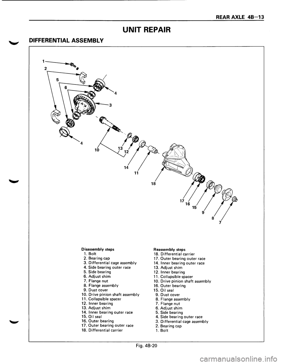
UNIT REPAIR
DIFFERENTIAL ASSEMBL V
1---.___. .......... ,
2 •
4
Disassembly steps 1. Bolt 2. Bearing cap 3. Differential cage assembly
4.
Side bearing outer race
5. Side bearing 6. Adjust shim
7. Flange nut
8. Flange assembly 9. Dust cover 10. Drive pinion shaft assembly
11. Collapsible spacer
12.
Inner bearing
13. Adjust shim
14. Inner bearing outer race
15. Oil seal
16. Outer bearing
17. Outer bearing outer race
18. Differential carrier
Reassembly steps
18. Differential carrier
17.
Outer bearing outer race
14. Inner bearing outer race
13. Adjust shim
12.
Inner bearing
11. Collapsible spacer 10. Drive pinion shaft assembly
16. Outer bearing
15. Oil seal 9. Dust cover 8. Flange assembly 7. Flange nut 6. Adjust shim 5. Side bearing
4. Side bearing outer race
3. Differential cage assembly 2. Bearing cap
1. Bolt
Fig. 48-20
REAR AXLE 48-13
Page 256 of 1928
48 -14 REAR AXLE
l•!•l DISASSEMBLY
~·
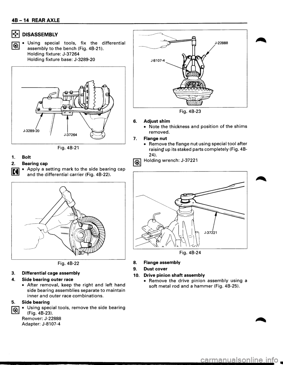
Using special tools, fix the differential
assembly
to the bench (Fig. 48-21 ).
Holding fixture: J-37264
Holding fixture base: J-3289-20
Fig. 48-21
1. Bolt
2. Bearing cap
~ • Apply a setting mark to the side bearing cap
l.!!.!l and the differential carrier (Fig. 48-22).
Fig. 48-22
3. Differential cage assembly
4. Side bearing outer race
• After removal, keep the right and left hand
side bearing
assemblies separate to maintain
inner and outer race combinations.
5. Side bearing
l'i5\J • U~ing special tools, remove the side bearing
~ (F1g. 48-23).
Remover: J-22888
Adapter: J-81 07-4
J·22888
Fig. 48-23
6. Adjust shim
• Note the thickness and position of the shims
removed.
7. Flange nut
• Remove the flange nut using special tool after
raisin~ up its staked parts completely (Fig. 48-
24).
1®.1 Holding wrench: J-37221
Fig. 48-24
8. Flange assembly
9. Dust cover
10. Drive pinion shaft assembly
•
Remove the drive pinion assembly using a
soft metal rod and a hammer (Fig. 48-25).
..
Page 257 of 1928
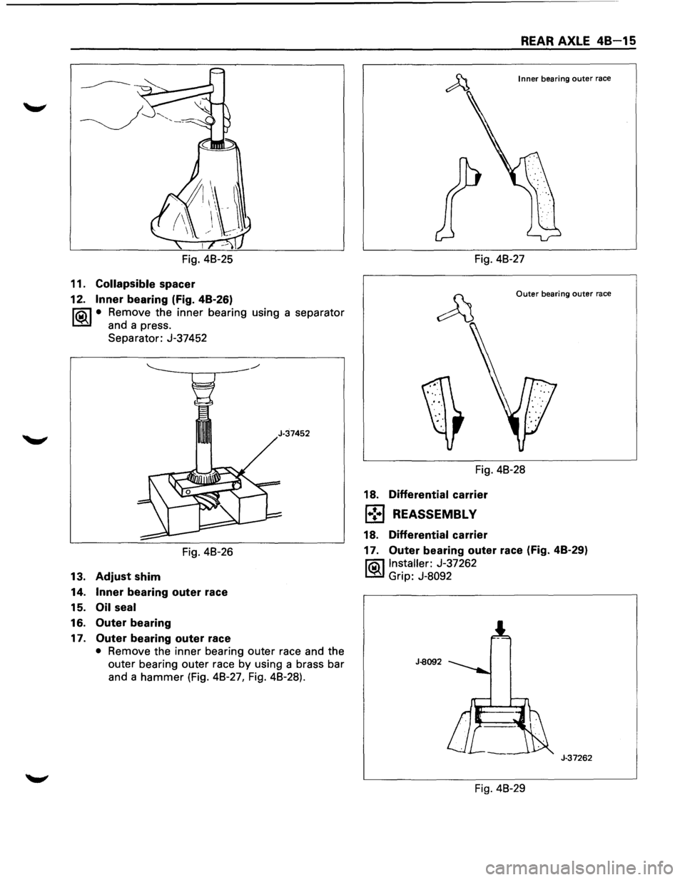
Fig. 48-25
11.
Collapsible spacer
12. Inner bearing (Fig. 48-26)
l?.iil • Remove the inner bearing using a separator
~ and a press.
Separator: J-37452
Fig. 48-26
13.
Adjust shim
14. Inner bearing outer race
15.
Oil seal
16. Outer bearing
17. Outer bearing outer race
• Remove the inner bearing outer race and the
outer bearing outer race by using a brass bar
and a
hammer (Fig. 48-27, Fig. 48-28).
REAR AXLE 48-15
Inner bearing outer race
Fig. 48-27
Outer bearing outer race
Fig. 48-28
18.
Differential carrier
1•:-1 REASSEMBL V
18. Differential carrier
17. Outer bearing outer race (Fig. 48-29)
l?.iil Installer: J-37262
~ Grip: J-8092
J-8092
J-37262
Fig. 48-29
Page 261 of 1928
7. Flange nut
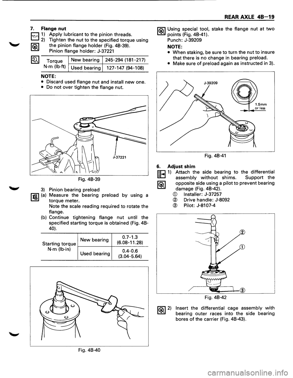
1~11) Apply lubricant to the pinion threads.
2) Tighten the nut to the specified torque using
1®.1 the pinion flange holder (Fig. 48-39).
Pinion
flange holder: J-37221
Torque
New bearing 245-294
(181-217)
N·m (lb·ft) Used bearing
127-147 (94-108)
NOTE:
• Discard used flange nut and install new one.
• Do not over tighten the flange nut.
Fig. 48-39
3) Pinion bearing preload
rfiil (a) Measure the bearing preload by using a
1..!!.1 torque meter.
Note the
scale reading required to rotate the
flange.
(b) Continue tightening flange nut until the
specified starting torque is obtained (Fig. 48-
40).
New bearing 0
·7
-1
·3
Starting
torque f-------+--(6_._08_-_1_1_.2_8_) _
N·m (lb·in) 0.4-0.6 Used bearing
(3.04-5.64)
Fig.
48-40
REAR AXLE 48-19
1'?.3\1 Using special tool, stake the flange nut at two
~points (Fig. 48-41).
Punch:
J-39209
NOTE:
• When staking, be sure to turn the nut to insure
that there is no change in bearing
preload.
•
Make sure of preload again as instructed in 3).
Fig. 48-41
6. Adjust shim
m=J 1) Attach the side bearing to the differential
~ assembly without shims. Support the
1®.1 opposite side using a pilot to prevent bearing
damage (Fig. 48-42).
~ 2)
CD Installer: J-37257
® Drive handle: J-8092
® Pilot: J-81 07-4
Fig. 48-42
Insert the differential cage assembly with
bearing outer races into the side bearing
bores
of the carrier (Fig. 48-43).
Page 263 of 1928
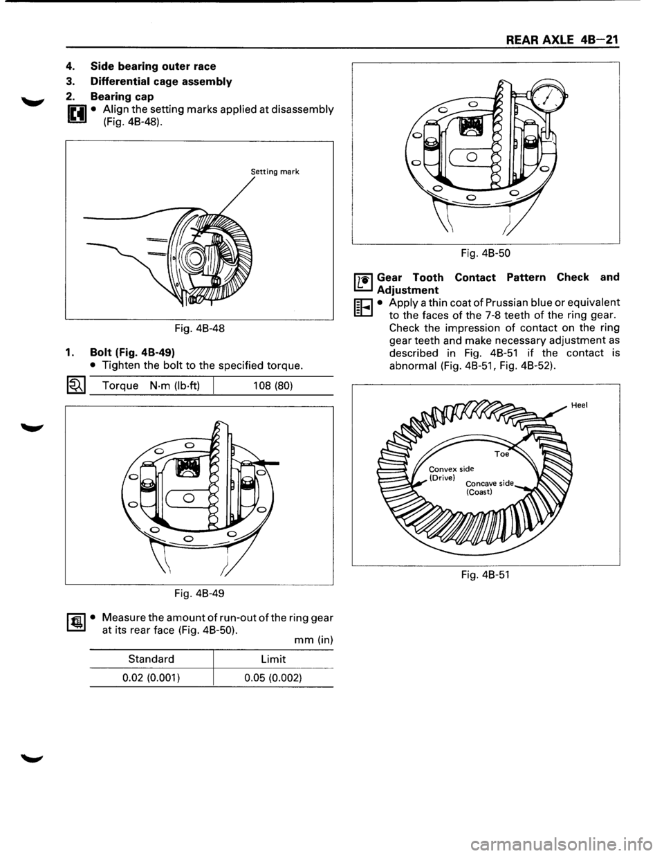
4. Side bearing outer race
3. Differential cage assembly
2. Bearing cap
0 • Align the setting marks applied at disassembly
1!!:!.1 (Fig. 48-48).
Setting mark
Fig. 48-48
1. Bolt (Fig. 4B-49)
• Tighten the bolt to the specified torque.
~~~ Torque N·m (lb·ft) 108 (80)
Fig. 48-49
~·
Measure the amount of run-out of the ring gear
at its rear face (Fig. 48-50).
mm (in)
Standard Limit
0.02 (0.001)
0.05 (0.002)
REAR AXLE 48-21
Fig. 48-50
l'7'1il Gear Tooth Contact Pattern Check and
I.£..J Adjustment
r;o • Apply a thin coat of Prussian blue or equivalent
EC.I to the faces of the 7-8 teeth of the ring gear.
Check the impression
of contact on the ring
gear teeth and make necessary adjustment
as
described in Fig. 48-51 if the contact is
abnormal (Fig.
48-51, Fig. 48-52).
Fig. 48-51
Page 265 of 1928
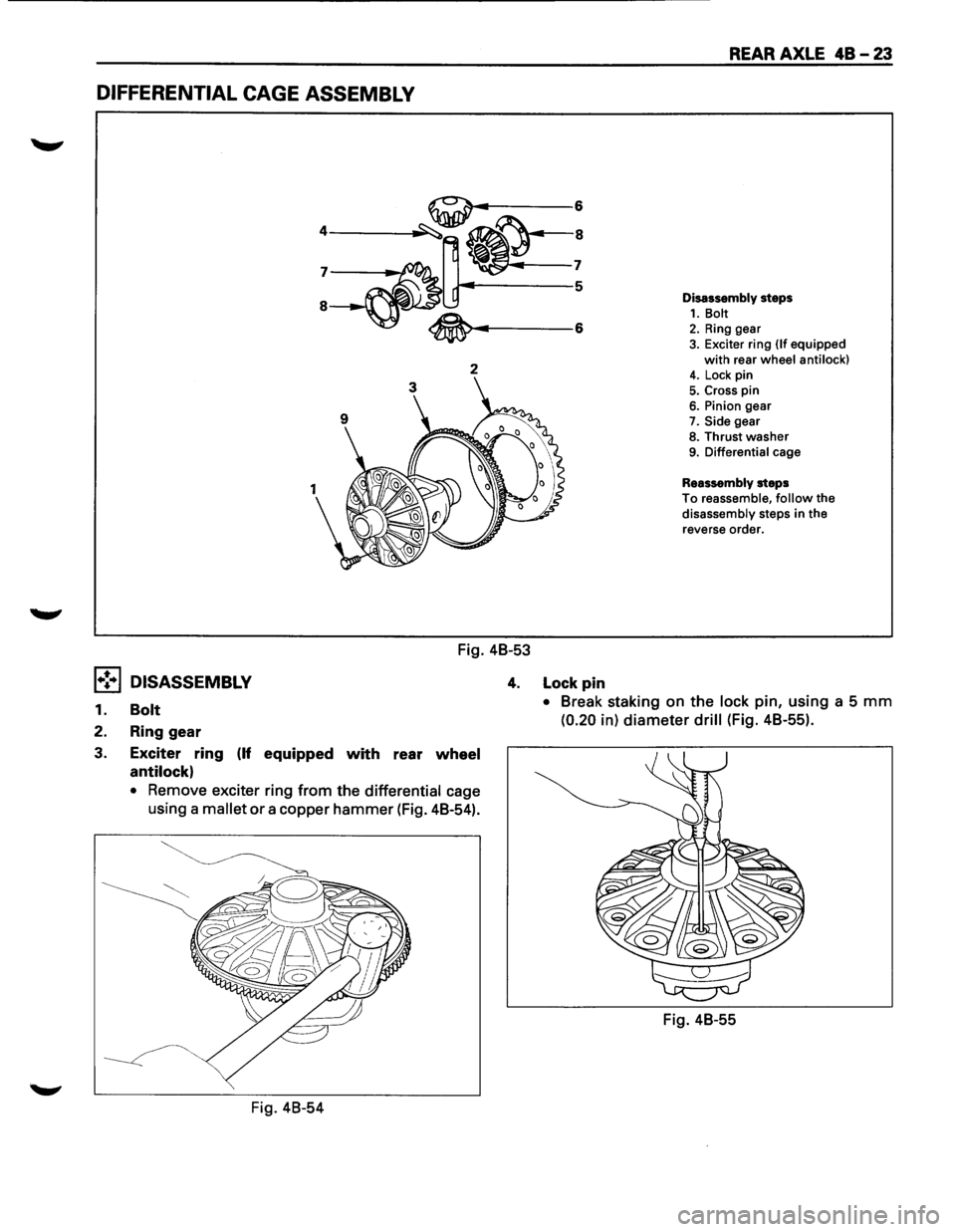
DIFFERENTIAL CAGE ASSEMBLY
2
Fig. 48-53
REAR AXLE 48-23
Disassembly steps 1. Bolt 2. Ring gear 3. Exciter ring (If equipped
with rear wheel anti lock) 4. Lock pin
5. Cross pin 6. Pinion gear
7. Side gear
8. Thrust washer 9. Differential cage
Reassembly steps
To reassemble, follow the
disassembly steps in the
reverse order.
1•! .. 1 DISASSEMBLY 4. Lock pin
1. Bolt
2. Ring gear
3. Exciter
ring (If equipped with rear wheel
antilock)
• Remove exciter ring from the differential cage
using a mallet
or a copper hammer (Fig. 48-54).
Fig. 48-54
• Break staking on the lock pin, using a 5 mm
(0.20 in) diameter drill (Fig. 48-55).
Fig. 48-55
Page 266 of 1928
48-24 REAR AXLE
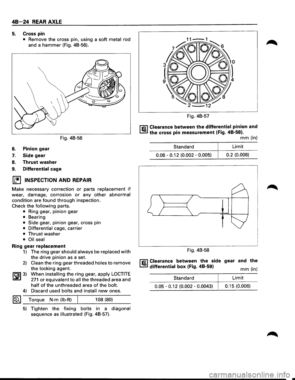
5. Cross pin
• Remove the cross pin, using a soft metal rod
and a hammer (Fig. 48-56).
Fig. 48-56
6. Pinion gear
7. Side gear
8. Thrust washer
9. Differential cage
(1!] INSPECTION AND REPAIR
Make necessary correction or parts replacement if
wear, damage, corrosion or any other abnormal
condition are found through inspection.
Check the following parts.
• Ring gear, pinion gear
• Bearing
• Side gear, pinion gear, cross pin
• Differential cage, carrier
• Thrust washer
• Oil seal
Ring gear replacement
1) The ring gear should always be replaced with
the drive pinion as a set.
2) Clean the ring gear threaded holes to remove
the
locking agent.
~~~3) When installing the ring gear, apply LOCTITE
271 or equivalent to all the threaded area and
half of the unthreaded area of the bolt.
4) Discard used bolts and install new ones.
1~1 Torque N·m (lb·ft) 108 (80)
5) Tighten the fixing bolts in a diagonal
sequence as illustrated (Fig. 48-57). Fig.
48-57
l'fil Clearance between the differential pinion and
1..!:.1 the cross pin measurement (Fig. 48-58).
mm (in)
Standard Limit
0.06 -0.12
(0.002 -0.005) 0.2
(0.008)
Fig. 48-58
l'fil Clearance between the side gear and the
1..!:.1 differential box (Fig. 48-59) mm (in)
Standard
Limit
0.05 -0.12 (0.002 -0.0043) 0.1 5 (0.006)
Page 267 of 1928
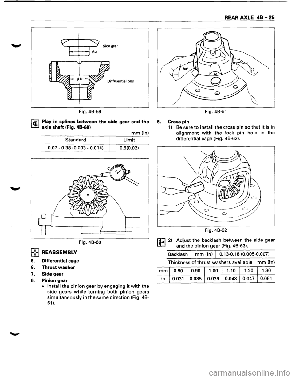
Side gear
Differential box
Fig. 4B-59
l'fiil Play in splines between the side gear and the
1.!!.1 axle shaft (Fig. 48-60)
Standard
0.07-0.38 (0.003-0.014)
Fig. 4B-60
l•!•l REASSEMBLY
9. Differential cage
8.
Thrust washer
7. Side gear
6. Pinion gear
mm (in)
Limit
0.5(0.02)
• Install
the pinion gear by engaging it with the
side gears while turning both pinion gears
simultaneously in the same direction (Fig. 4B-
61).
REAR AXLE 48 - 25
Fig. 4B-61
5. Cross pin
1) Be sure to install the cross pin so that it is in
alignment with the lock pin hole in the
differential cage (Fig. 4B-62).
Fig. 4B-62
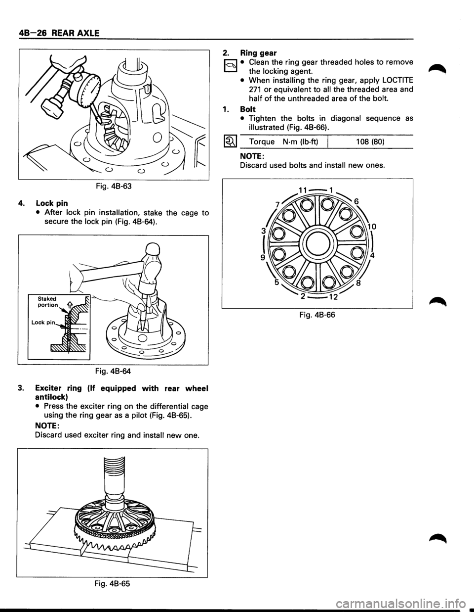
1§1-... 1 2) Adjust the backlash between the side gear
and the pinion gear (Fig. 4B-63).
Backlash mm (in) I 0.13-0.18 (0.005-0.007)
Thickness of thrust washers available mm (in)
mm 0.80 0.90 1.00
1.10 1.20
1.30
in 0.031
0.035 0.039 0.043
0.047 0.051
Page 268 of 1928
48-26 REAR AXLE
Fig. 48-63
4. Lock pin
• After lock pin installation, stake the cage to
secure the lock pin (Fig. 48-64).
Fig. 48-64
3. Exciter ring (If equipped with rear wheel
antilock)
• Press the exciter ring on the differential cage
using the ring gear
as a pilot (Fig. 48-65).
NOTE:
Discard used exciter ring and install new one.
Fig. 48-65
2. Ring gear
r;:::;J • Clean the ring gear threaded holes to remove
D the locking agent.
• When installing the ring gear, apply LOCTITE
271 or equivalent to all the threaded area and
half of the unthreaded area of the bolt.
1. Bolt
• Tighten the bolts in diagonal sequence as
illustrated (Fig. 48-66).
l~l Torque N·m (lb·ft) I 108 (80)
NOTE:
Discard used bolts and install new ones.
Fig. 48-66
Page 269 of 1928
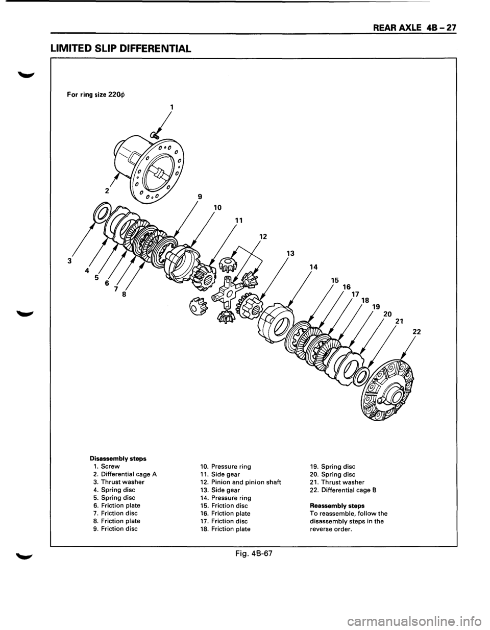
LIMITED SLIP DIFFERENTIAL
For ring size 220cf>
9
10
12
3
8
Disassembly steps 1. Screw 10. Pressure ring 2. Differential cage A
11. Side gear 3. Thrust washer 12. Pinion and pinion shaft 4. Spring disc
13. Side gear 5. Spring disc
14. Pressure ring 6. Friction plate 15. Friction disc 7. Friction disc 16. Friction plate 8. Friction plate 17. Friction disc 9. Friction disc 18. Friction plate
Fig. 48-67
REAR AXLE 48-27
16 17
19. Spring disc
20. Spring disc
18
21. Thrust washer
19
22. Differential cage B
Reassembly steps
20
To reassemble, follow the disassembly steps in the reverse order.
21