door lock ISUZU TROOPER 1995 Service Manual
[x] Cancel search | Manufacturer: ISUZU, Model Year: 1995, Model line: TROOPER, Model: ISUZU TROOPER 1995Pages: 1928
Page 1469 of 1928
CHASSIS ELECTRICAL 8 ~ 277
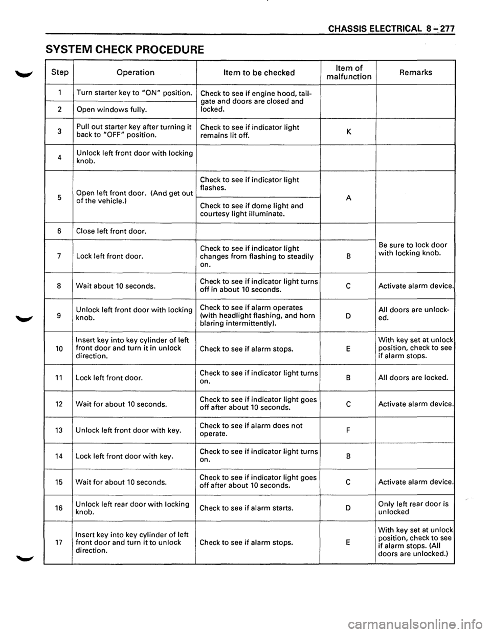
SYSTEM CHECK PROCEDURE
Step Operation Item to be checked Item of Remarks malfunction
1
Turn starter key to "ON" position. Check to see if engine hood, tail-
gate and doors are closed and
2
Open windows fully. locked.
3
Pull out starter key after turning it Check to see if indicator light K back to "OFF" position.
remains lit off.
4 Unlock
left
front door with locking
knob.
Check to see if indicator light
Open left front door. (And get out flashes.
5 A
of the vehicle.) Check to see if dome light and
courtesy light illuminate.
6 Close left front door.
Check to see if indicator light Be sure to lock door
7
Lock left front door.
changes from flashing to steadily B with locking knob.
on.
8 Wait about 10 seconds. Check to see if indicator light turns c Activate alarm device. off in about 10 seconds.
Unlock left
front door with locking Check to see if alarm operates All doors are unlock-9 knob. (with
headlight flashing, and horn D ed.
blaring intermittently).
Insert key into key cylinder of left With
key set at unlock
10 front door and turn it in unlock Check to see if alarm stops. E position, check to see
direction. if alarm stops.
11 Lock left front door. Check to see if indicator light turns
B All doors are locked.
on.
12 Wait for about 10 seconds. Check to see if indicator light goes c Activate alarm device. off after about 10 seconds.
13 Unlock left front door with key. Check to see if alarm does not F
operate.
14 Lock left front door with key. Check to see if indicator light turns
B
on.
15 Wait for about 10 seconds. Check to see if indicator light goes c Activate alarm device. off after about 10 seconds.
16 Unlock left rear door with locking Check to see if alarm starts. D Only left rear door is
knob. unlocked
Insert key
into key cylinder of left With
key set at unlock
position, check to see 17 front door and turn it to unlock Check to see if alarm stops. E if alarm stops. (All direction.
doors are unlocked.)
Page 1470 of 1928
8-278 CHASSIS ELECTRICAL
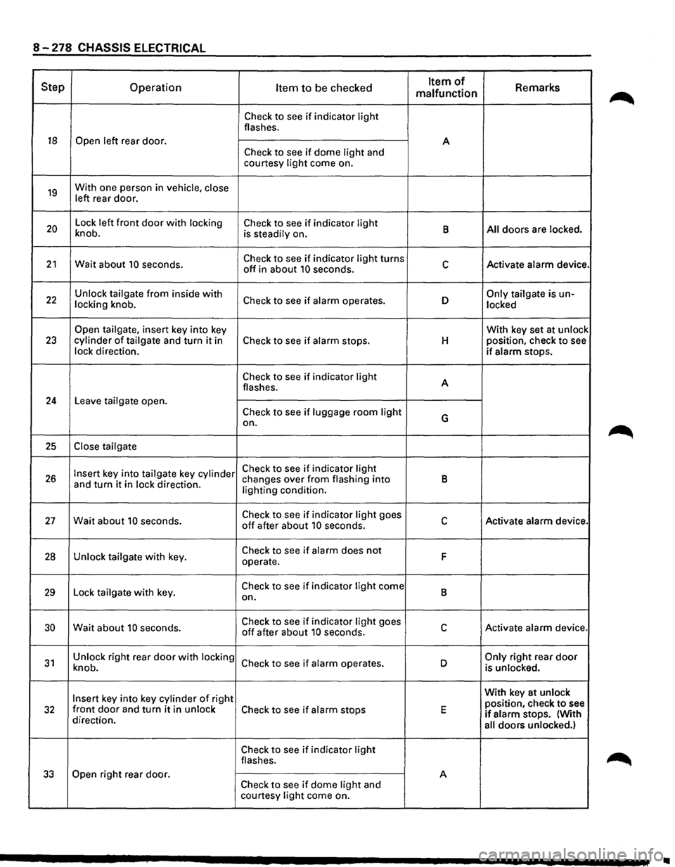
Step Operation Item to be checked Item of Remarks malfunction
Check to see if indicator light flashes.
18 Open left rear door.
A
Check to see if dome light and
courtesy light come on.
19 With one person in vehicle, close
left rear door.
20 Lock left front door with locking Check to see if indicator light B All doors are locked.
knob. is steadily on.
21 Wait about 10 seconds. Check to see if indicator light turns c Activate alarm device. off in about 10 seconds.
22 Unlock tailgate from inside with Check to see if alarm operates. D Only tailgate is un-
locking knob.
locked
Open tailgate, insert key into key With key set at unlock 23 cylinder of tailgate and turn it in Check to see if alarm stops. H position,
check to see
lock direction. if alarm stops.
Check to see if indicator light A
flashes.
24 Leave tailgate open.
Check to see if luggage room light G on.
25 Close tailgate
Insert key into tailgate key cylinder Check to see if indicator light 26 and turn it in lock direction. changes
over from flashing into B lighting condition.
27 Wait about 10 seconds. Check to see if indicator light goes c Activate alarm device. off after about 10 seconds.
28 Unlock tailgate with key. Check to see if alarm does not F operate.
29 Lock tailgate with key. Check to see if indicator light come B on.
30 Wait about 10 seconds. Check to see if indicator light goes c Activate alarm device. off after about 10 seconds.
31 Unlock right rear door with locking Check to see if alarm operates.
D Only right rear door knob.
is unlocked.
Insert key into key cylinder of right With
key at unlock
position, check to see 32 front door and turn it in unlock Check to see if alarm stops E if alarm stops. (With
direction.
all doors unlocked.)
Check to see if indicator light flashes.
33 Open right rear door.
A Check to see if dome light and
courtesy light come on.
..
Page 1472 of 1928
8-282 CHASSIS ELECTRICAL
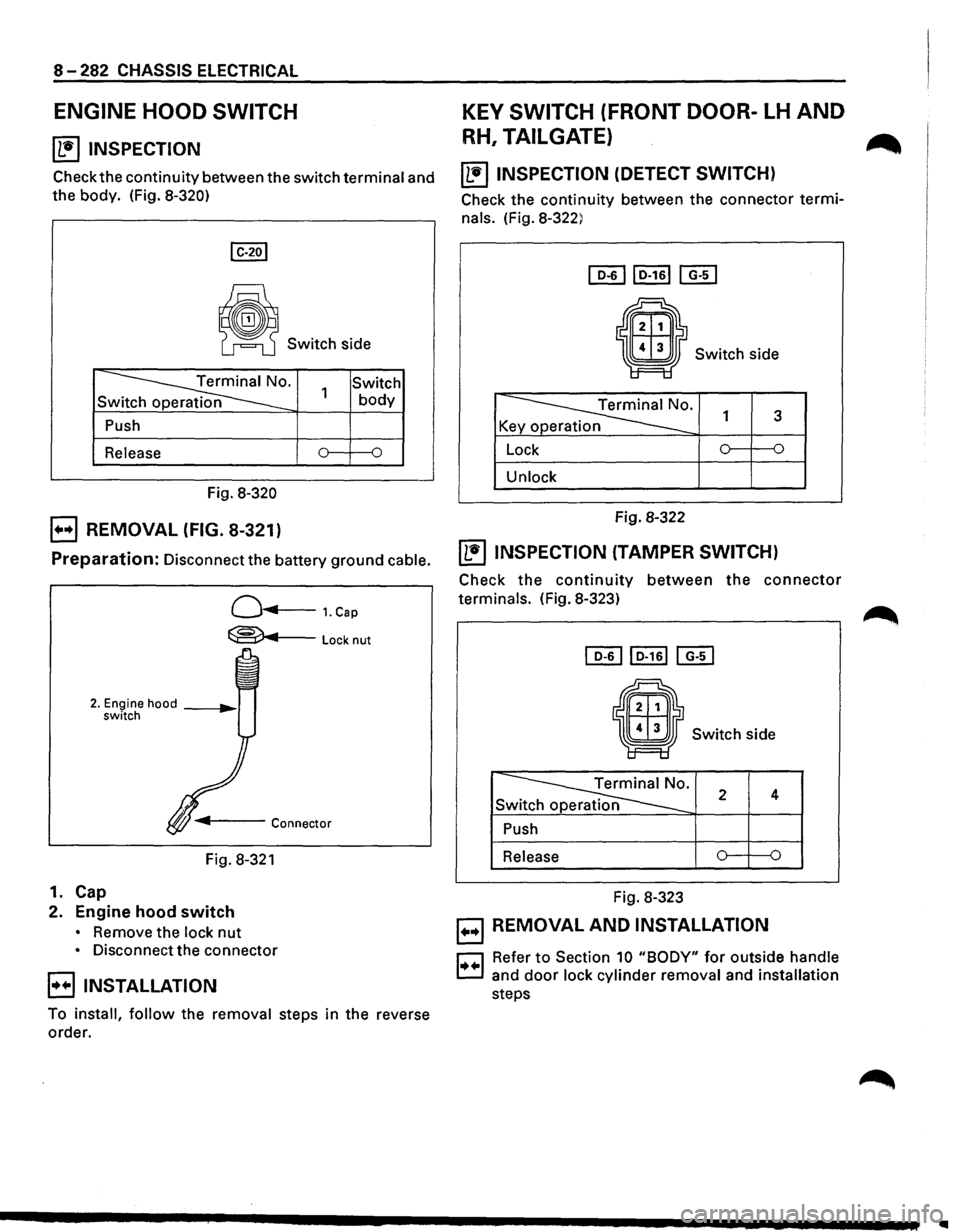
ENGINE HOOD SWITCH
~ INSPECTION
Check the continuity between the switch terminal and
the body. (Fig. 8-320)
~ Switch side
~· Sw
Push
Release
Fig.
8-320
E) REMOVAL (FIG. 8-321)
Switch 1 body
Preparation: Disconnect the battery ground cable.
Q...,..,...___ 1. Cap
~Locknut
Fig. 8-321
1. Cap
2. Engine hood switch
• Remove the lock nut
• Disconnect the connector
B INSTALLATION
To install, follow the removal steps in the reverse
order.
KEY SWITCH (FRONT DOOR-LH AND
RH, TAILGATE) ...
~ INSPECTION (DETECT SWITCH)
Check the continuity between the connector termi
nals. (Fig. 8-322)
Switch side
~· K y p 1 3
Lock 0 {)
Unlock
Fig. 8-322
~ INSPECTION (TAMPER SWITCH)
Check the continuity between the connector
terminals. (Fig. 8-323)
• Switch side
~· Sw 2 4
Push
Release
Fig. 8-323
B REMOVAL AND INSTALLATION
r::J Refer to Section 10 "BODY" for outside handle
c:.:J and door lock cylinder removal and installation
steps
Page 1473 of 1928
DOOR LOCK ACTUATOR (fRT DOOR
LH & RH, RR DOOR -LH & RH, TAIL-
~ GATE)
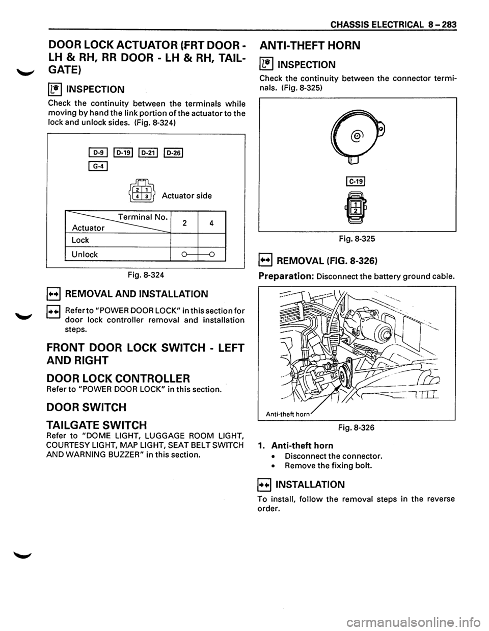
~ INSPECTION
Check the continuity between the terminals while
moving by hand the link portion of the actuator to the
lock and unlock sides. (Fig. 8-324)
[QI] I D-191 I D-211 I D-261
[E)
~
~ Actuator side
~· 2 4 r
Lock
Unlock
Fig. 8-324
B REMOVAL AND INSTALLATION
1++1 Referto "POWER DOOR LOCK" in this section for
door lock controller removal and installation
steps.
FRONT DOOR LOCK SWITCH -LEFT
AND RIGHT
DOOR LOCK CONTROLLER
Refer to "POWER DOOR LOCK" in this section.
DOOR SWITCH
CHASSIS ELECTRICAL 8-283
ANTI-THEFT HORN
~ INSPECTION
Check the continuity between the connector termi
nals. (Fig. 8-325)
Fig. 8-325
B REMOVAL (FIG. 8-326)
Preparation: Disconnect the battery ground cable.
TAILGATE SWITCH Fig. 8-326
Refer
to "DOME LIGHT, LUGGAGE ROOM LIGHT,
COURTESY LIGHT,
MAP LIGHT, SEAT BELT SWITCH 1. Anti-theft horn
AND WARNING BUZZER" in this section. • Disconnect the connector.
• Remove the fixing bolt.
B INSTALLATION
To install, follow the removal steps in the reverse
order.
Page 1637 of 1928
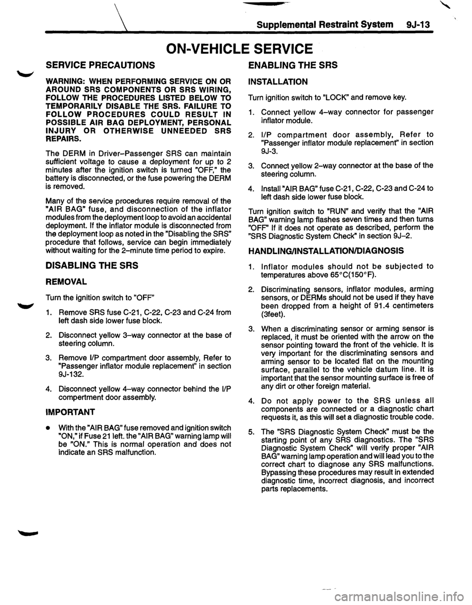
Supplemental Restraint System 9J-13
ON-VEHICLE SERVICE
SERVICE PRECAUTIONS
WARNING: WHEN PERFORMING SERVICE ON OR
AROUND SRS COMPONENTS OR SRS WIRING,
FOLLOW
THE PROCEDURES LISTED BELOW TO
TEMPORARILY DISABLE THE SRS. FAILURE TO
FOLLOW PROCEDURES COULD RESULT IN
POSSIBLE AIR
BAG DEPLOYMENT, PERSONAL
INJURY OR OTHERWISE
UNNEEDED SRS
REPAIRS.
The DERM in Driver-Passenger SRS can maintain
sufficient voltage to cause a deployment for up to 2
minutes after the ignition switch is turned
"OFF," the
battery is disconnected, or the fuse powering the DERM
is removed.
Many of the service procedures require removal of the
"AIR BAG" fuse, and disconnection of the inflator
modules from the deployment loop to avoid an accidental
deployment.
If the inflator module is disconnected from
the deployment loop as noted in the "Disabling the
SRS"
procedure that follows, service can begin immediately
without waiting for the 2-minute time period to expire.
DISABLING THE SRS
REMOVAL
Turn the ignition switch to "OFF"
1. Remove SRS fuse C-21, C-22, C-23 and C-24 from
left dash side lower fuse block.
2. Disconnect yellow 3-way connector at the base of
steering column.
3. Remove 1/P compartment door assembly, Refer to
"Passenger inflator module replacement" in section
9J-132.
4. Disconnect yellow 4-way connector behind the 1/P
compartment door assembly.
IMPORTANT
• With the "AIR BAG" fuse removed and ignition switch
"ON," if Fuse 21 left. the "AIR BAG" warning lamp will
be "ON." This is normal operation and does not
indicate an
SRS malfunction.
ENABLING THE SRS
INSTALLATION
Turn ignition switch to "LOCK" and remove key.
1. Connect yellow 4-way connector for passenger
inflator module.
2. 1/P compartment door assembly, Refer to
"Passenger inflator module replacemenf' in section
9J-3.
3. Connect yellow 2-way connector at the base of the
steering column.
4. Install "AIR BAG" fuse C-21, C-22, C-23 and C-24 to
left dash side lower fuse block.
Turn ignition switch to
"RUN" and verify that the "AIR
BAG"
warning lamp flashes seven times and then turns
"OFP' If it does not operate as described, perform the
"SRS Diagnostic System Check" in section 9J-2.
HANDLING/INSTALLATION/DIAGNOSIS
1. Inflator modules should not be subjected to
temperatures above
65°C{150°F).
2. Discriminating sensors, inflator modules, arming
sensors, or DERMs should not be used if they have
been dropped from a height
of 91.4 centimeters
{3feet).
3. When a discriminating sensor or arming sensor is
replaced, it must be oriented with the arrow on the
sensor pointing toward the front of the vehicle.
It is
very important for the discriminating sensors and
arming sensor to be located flat on the mounting
surface, parallel to the vehicle datum line.
It is
important that the sensor mounting surface is free of
any dirt or other foreign material.
4. Do not apply power to the SRS unless all
components are connected or a diagnostic chart
requests it, as this
will set a diagnostic trouble code.
5. The "SRS Diagnostic System Check" must be the
starting point of any
SRS diagnostics. The "SRS
Diagnostic System Check" will verify proper "AIR
BAG"
warning lamp operation and will lead you to the
correct chart to diagnose any
SRS malfunctions.
Bypassing these procedures may result
in extended
diagnostic time, incorrect diagnosis, and incorrect
parts replacements.
Page 1646 of 1928
9J-22 Supplemental Restraint System
AIR BAG TO EXPAND IN THE UNLIKELY EVENT OF
ACCEIDENTAL DEPLOYMENT. FAILURE TO
FOLLOW PROCEDURES MAY RESULT IN
PERSONAL INJURY.
26. Temporarily store the inflator module with the bag
facing up, away from the surface upon which it rests.
27.
Call the Technical Assistance group for further
assistance.
DEPLOYMENT INSIDE VEHICLE(VEHICLE
SCRAPPING PROCEDURE)
Deployment inside vehicle is proper when the vehicle is
to be destroyed or
salvaged for component parts. This
includes, but is not limited to, the following situations.
1. The vehicle has completed its useful life.
2. The vehicle has been damaged beyond repair in a
non-deployment type accident.
3. The vehicle has been stripped or damaged beyond
repair
in a theft.
4. The vehicle will be salvaged for component parts to
be
used on a vehicle with a different Vehicle
Identification Number (VIN) as opposed to being
rebuilt as same VIN. Never use SRS components
from another
vehicle. This is done to ensure SRS
system integrity since only new SRS system
components.
WARNING: FAILURE TO FOLLOW PROPER SRS
INFLATOR MODULE DISPOSAL PROCEDURES
CAN RESULT IN AIR BAG DEPLOYMENT WHICH
MAY CAUSE PERSONAL INJURY. UNDEPLOYED
INFLATOR MODULES MUST NOT BE DISPOSED OF
THROUGH NORMAL REFUSE CHANNELS. THE
UNDEPLOYED INFLATOR MODULE CONTAINS
SUBSTANCES THAT CAL CAUSE SEVERE ILLNESS
OR
PERSONAL INJURY IF THE SEALED
CONTAINER IS DAMAGED DURING DISPOSAL.
DISPOSAL IN ANY MANNER INCONSISTENT WITH
PROPER PROCEDURES MAY BE A VIOLATION OF
FEDERAL, STATE AND/OR LOCAL LAWS.
1. Turn ignition switch to "LOCK," remove key and put
on safety glasses.
2. Remove all loose objects from front seats.
3. Disconnect driver inflator module, yellow 3-way
connector located at the base of the steering column.
4. Cut the driver inflator module yellow 2-way harness
connector from the
vehicle leaving at least 16 cm(six
inches) of wire at the connector.
5. Strip 13 mm(1/2 inch) of insulation from each wire
lead of the connector.
6. Cut two 900 cm(30 feet) deployment wires from
0.8mm2(18 gauge) or thicker
multi-strand wire. These
wires
will be used to fabricate the driver
deployment harness.
7. Strip 13 mm(1/2 inch) of insulation from both ends of
the wires cut
in the previous step.
8. Short the wires by twisting together one end from
each. Deployment wires
shall remain shorted and
not
be connected to a power source until the air bag
is to be
deployed.
WARNING: FAILURE TO
FOLLOW PROCEDURES
IN
THE ORDER LISTED COULD RESULT IN
PERSONAL INJURY. NEVER CONNECT
DEPLOYMENT WIRES TO ANY POWER SOURCE
BEFORE CONNECTING DEPLOYMENT WIRES TO
THE INFLATOR MODULE LEADS. DEPLOYMENT
WIRES SHALL REMAIN SHORTED AND NOT BE
CONNECTED TO A POWER SOURCE UNTIL THE
AIR BAG IS TO BE DEPLOYED. THE INFLATOR
MODULE WILL IMMEDIATELY DEPLOY THE AIR
BAG WHEN A POWER SOURCE IS CONNECTED TO
IT. WEAR SAFETY GLASSES THROUGHOUT THIS
ENTIRE DEPLOYMENT AND DISPOSAL
PROCEDURE.
9. Twist together one connector wire lead to one
deployment wire. The connection should be
mechanically secure.
10. Bend twisted connection made in the previous step
flat and wrap tightly with electrical tape to insulate ~
and secure.
11. Twist together, bend and tape the remaining
connector wire lead to the remaining deployment
wire.
12. Connect the deployment harness to the driver
inflator module, yellow 2-way connector at the base
of the steering
column. Route deployment harness
out the driver side of the
vehicle.
WARNING:
DEPLOYMENT WIRES SHALL REMAIN
SHORTED
AND NOT BE CONNECTED TO A POWER
SOURCE UNTIL THE AIR BAG IS TO BE DEPLOYED.
THE INFLATOR MODULE WILL IMMEDIATELY
DEPLOY THE AIR BAG WHEN A POWER SOURCE IS
CONNECTED TO IT.
CONNECTING THE DEPLOYMENT WIRES TO THE
POWER
SOURCE SHOULD ALWAYS BE THE FINAL
STEP IN
THE INFLATOR MODULE DEPLOYMENT
PROCEDURE. FAILURE TO FOLLOW
PROCEDURES IN THE ORDER LISTED COULD
RESULT IN PERSONAL INJURY.
13. Disconnect passenger inflator module, yellow 2-way
connector located behind 1/P compartment door
assembly.
14. Cut the passenger inflator module harness
connector from the vehicle leaving at least 16 cm(six
inches) of wire at the connector).
Page 1741 of 1928
Supplemental Restraint System 9J-117
SERVICE PRECAUTIONS
CAUTION: WHEN PERFORMING SERVICE ON OR
AROUND SRS COMPONENTS OR SRS WIRING,
FOLLOW
THE PROCEDURES LISTED BELOW TO
TEMPORARILY
DISABLE THE SRS. FAILURE TO
FOLLOW PROCEDURES COULD RESULT IN
POSSIBLE AIR BAG DEPLOYMENT, PERSONAL
INJURY OR OTHERWISE UNNEEDED SRS
REPAIRS.
The DERM in Driver-Passenger SRS can maintain
sufficient voltage to cause a deployment for up to 2
minutes after the ignition switch is turned to
"OFF," the
battery is disconnected, or the fuse powering the DERM
is removed.
Many of the service procedures require removal of the
"AIR BAG" fuse, and disconnection of the inflator
modules from the deployment loop to avoid an accidental
deployment.
If the inflator module is disconnected from
the deployment loop as noted in the "Disabling the
SRS"
procedure that follows, service can begin immediately
without waiting for the 2 minute time period to expire.
DISABLING THE SRS
REMOVAL
• Turn the steering wheel so that the vehicle's wheels
are pointing straight ahead.
• Turn the ignition switch to "OFF"
1. Remove SRS fuse C-21, C-22, C-23 and C-24 from
left dash side lower fuse block.
2. Disconnect yellow
3-way connector at the base of
the steering column.
3. Remove
liP compartment door assembly, Refer to
"Passenger inflator module replacemenf' in section
9J-135.
4. Disconnect yellow 4-way connector behind the liP
compartment door assembly.
NOTE
• With the" AIR BAG" fuse removed and ignition switch
"ON," the "AiR BAG" warning lamp will be "ON." This
is normal operation and does not indicate
an SRS
malfunction.
ENABLING THE SRS
INSTALLATION
Turn ignition switch to "LOCK" and remove key.
1. Connect yellow 4-way connector of passenger
inflator module.
2. Install liP compartment door assembly, Refer to
"Passenger inflator module replacement" in section
9J-3.
3. Connect yellow 3-way connector at the base of the
steering column.
4. Install" AIR BAG" fuse C-21, C-22, C-23 and C-24 to
left dash side lower fuse block.
Tum ignition switch to
"RUN" and verify that the "AIR
BAG"
warning lamp flashes seven times and then turns
"OFF" If it does not operate as described, perform the
"SRS Diagnostic System Check" in section 9J-32.
HANDLING/INSTALLATION/DIAGNOSIS
1. Inflator modules should not be subjected to
temperatures above 65°C(150°F).
2. Discriminating s~nsors, inflator modules, arming
sensors, or DERMs should not be used if they have
been dropped from a height of 1
00 centimeters (3.28
feet) or more.
3. When a discriminating sensor or arming sensor is
replaced, it MUST be oriented with the arrow
on the
sensor pointing toward the front of the vehicle.
It is
very important for the discriminating sensors and
arming sensor to be located flat on the mounting
surface, parallel to the vehicle datum line.
It is
important that the sensor mounting surface is free of
any dirt or other foreign material.
4. Do not apply power to the SRS unless all
components are connected or a diagnostic chart
requests it, as this
will set a diagnostic trouble code.
5. The
"SRS Diagnostic System Check'' must be the
starting point of any SRS diagnostics. The
"SRS
Diagnostic System Check" will verify proper "AIR
BAG" warning lamp operation and will lead you to the
correct chart to diagnose any SRS malfunctions.
Bypassing these procedures may result in extended
diagnostic time, incorrect diagnosis, and incorrect
parts replacements.
INSPECTIONS REQUIRED AFTER ACCI
DENT
CAUTION: CERTAIN SRS COMPONENTS MUST BE
REPLACED AFTER A FRONTAL
CRASH INVOLVING
AIR
BAG DEPLOYMENT.
In all types of accident regardless of "Air Bag"
deployment, visually inspect all the following
components and their points and replace as required:
- Passenger
Inflator Module
- Steering wheel
- SRS coil assembly
- Steering column
- Knee bolster and
Instrument panel mounting
Page 1759 of 1928
BODY 10-1
SECTION 10
BODY
\V CAUTION : When fasteners are removed, always reinstall them at the same location from which they
were removed. If a fastener needs to be replaced, use the correct part number fastener for
that application. If the correct part number fastener is not available, a fastener of equal size
and strength (or stronger)
may be used. Fasteners must be used when installing fasteners
that require it. If the above conditions are not followed, parts of system damage could result.
CONTENTS
General Description ................. 10-2 Front Door Weatherstrip ......... 10-53
On-Vehicle Service .................. 10-3 Rear Door Weatherstrip .......... 10-54
Body Dimension .................. 10-3 Front Door Seal Finisher ......... 10-54
Upper Body .................... 10-3 Rear Door Seal Finisher .......... 10-54
Front Section ................... 10-7 Door Mirror .................... 10-55
Room Section .................. 10-9 Body Side ....................... 10-56
Rear Section ................... 10-14 Interior Trim Panels ............. 10-56
Side Body ..................... 10-16 Center Pillar and Roof Side Trim
Window Glass .................. 10-19 Cover (L·W·B only) .............. 10-61
Front End ........................ 10-23 Roof Side Trim Cover (S·W·B only) . 10-62
Dash Side Trim Panel ............ 10-23 Front Pillar Trim Cover ........... 10-63
Assist Grip ..................... 10-23 Center Pillar Assist Grip .......... 10-63
Consoles ...................... 10-24 Assist Grip ..................... 10-63
Instrument Panel Assembly ....... 10-25 Fuel Filler lid Opener Cable ....... 10-64
Cross Beam Assembly ........... 10-30 Fuel Filler Door ................. 10-65
Doors ........................... 10-32 Rocker Protector (Without Wheel
Front Door Assembly ............ 10-32 Opening Extension) ............. 10-66
Rear Door Assembly ............. 10-32 Wheel Opening Extension
Door Strikers ................... 10-33 and Rocker Protector Assembly ... 10-67
Door Check Arm Assembly Mud Flaps (With Wheel Opening
(Front & Rear) .................. 10-34 Extension) ..................... 10-69
Front Door Trim Panel ........... 10-35 Ventilation Assembly ............ 10-70
Rear Door Trim Panel ............ 10-38 Quarter Flipper Glass Assembly
Door Wood Panel Assembly ...... 10-40 (S·W·B) ........................ 10-71
Front Window Regulator, Glass Rear End ........................ 10-72
and Glass Run .................. 10-41 Tailgate Assembly (LH) .......... 10-72
Rear Window Regulator and Tailgate Assembly (RH) .......... 10-73
Glass ......................... 10-43 Tailgate Strikers ................ 10-75
Front Door Lock Assembly ....... 10-45 Tailgate Trim Panel (LH) .......... 10-75
Rear Door Lock Assembly ........ 10-46 Tailgate Trim Panel (RH) .......... 10-76
Front Outside Handle and Tailgate Lock Assembly (LH) ...... 10-77
Door Lock Cylinder .............. 10-47 Tailgate Lock Assembly (RH) ...... 10-78
Rear Outside Handle ............. 10-48 Tailgate Inside Lock Knob ........ 10-79
Rear Door Fixed Glass and Tailgate Outside Handle and/or
Glass Run ...................... 10-49 Tailgate Lock Cylinder ........... 10-80
Door Inside Lock Knob ........... 10-50 Tailgate Stopper Assembly ....... 10-81
Door Inside Handle .............. 10-50 Tailgate Dove-tail ............... 10-81
Rear Door Inside Lock Knob Link .. 10-51 Tailgate Dove-tail Strikers ........ 10-82
Front Door Sash Moulding ....... 10-51 Tailgate Frame Cover (LH) ........ 10-82
Rear Door Moulding ............. 10-52 Tailgate Frame Cover (RH) ........ 10-83
Front Door Waist Seal ........... 10-52 Tailgate Sash Trim Cover ......... 10-83
Rear Door Waist Seal ............ 10-53 Tailgate Outer Weatherstrip ...... 10-84
Page 1794 of 1928
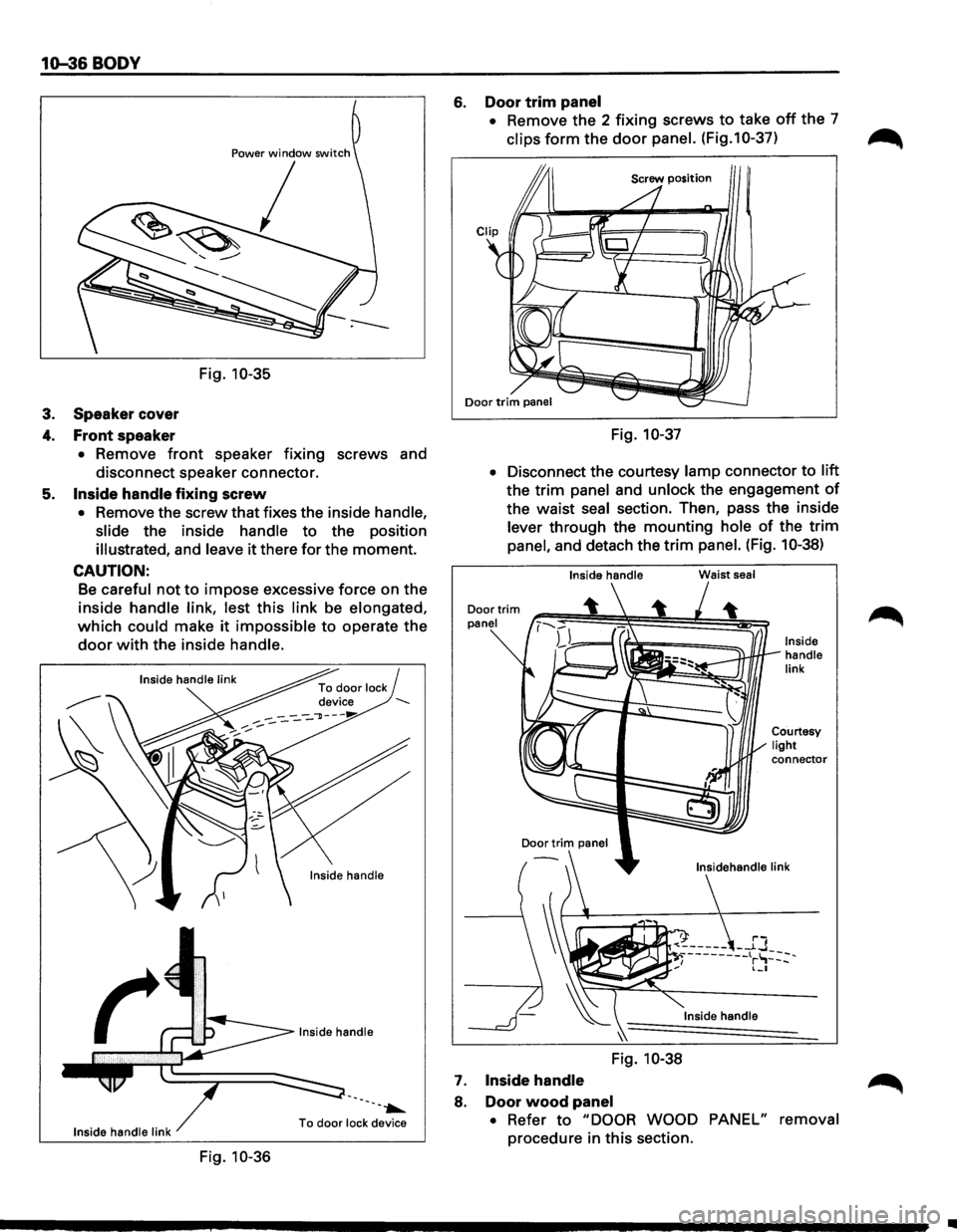
10-36 BODY
Power window switch
I
Fig. 10-35
3. Speaker cover
4. Front speaker
• Remove front speaker fixing screws and
disconnect speaker connector.
5.
Inside handle fixing screw
• Remove the screw that fixes the inside handle,
slide
the inside handle to the position
illustrated, and leave it there for the moment.
CAUTION:
Be careful not to impose excessive force on the
inside
handle link, lest this link be elongated,
which could make it impossible to operate the
door with the inside handle.
Inside handle
--.......
Inside handle link To door lock
device
Fig. 10-36
6. Door trim panel
• Remove the 2 fixing screws to take off the 7
clips form the door panel. (Fig.1 0-37)
Fig. 10-37
•
Disconnect the courtesy lamp connector to lift
the trim panel and unlock the engagement of
the waist seal section. Then, pass the inside
lever through the mounting hole of the trim
panel, and detach the trim panel. (Fig. 10-38)
Inside handle
Door
trim panel
Door
trim panel
7. Inside handle
Fig. 10-38
8. Door wood panel
Waist seal
Inside handle
link
connector
• Refer to "DOOR WOOD PANEL" removal
procedure in this section.
Ill
Page 1795 of 1928
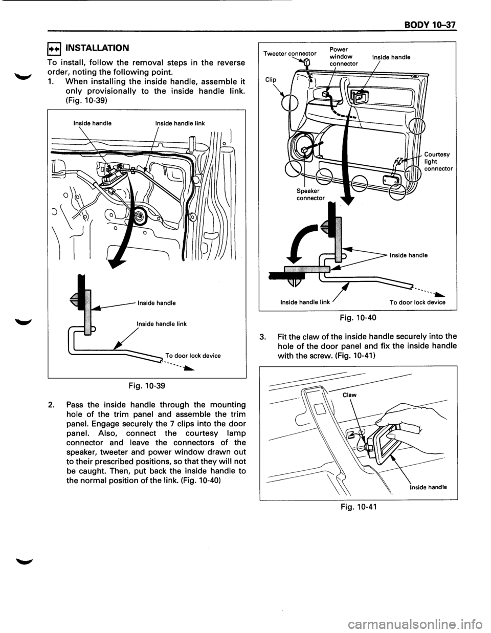
I••! INSTALLATION
To install, follow the removal steps in the reverse
order,
noting the following point.
1. When installing the inside handle, assemble it
only provisionally to the inside handle link.
(Fig. 10-39)
Inside handle
Inside handle link
To door lock device ·-. ·--~
Fig. 10-39
2. Pass the inside handle through the mounting
hole of the trim panel and assemble the trim
panel. Engage securely the 7 clips into the door
panel. Also, connect the courtesy lamp
connector and leave the connectors of the
speaker, tweeter and power
window drawn out
to their prescribed positions, so that they will not
be caught. Then, put back the inside handle to
the
normal position of the link. (Fig. 10-40)
Tweeter connector
Speaker connector Power
window connector
Inside
handle link
Fig. 10-40
BODY 10-37
Inside handle
·-. --~
To door lock device
3. Fit the claw of the inside handle securely into the
hole of the door panel and fix the inside handle
with the screw. (Fig. 10-41)
Inside handle
Fig. 10-41